Page 1203 of 3502

TRANSAXLE ASSEMBLY
CVT-197
D
E
F
G
H
I
J
K
L
MA
B
CVT
�Install transaxle assembly to engine assembly with a hoist.
�When installing fluid cooler tube to transaxle assembly, assem-
ble the part with the tube aligned with the rib.
�When installing transaxle to the engine, attach the fixing bolts in
accordance with the following standard.
�Align the positions of tightening nuts for drive plate with those of
the torque converter, and temporarily tighten the nuts. Then,
tighten the nuts with the specified torque.
CAUTION:
�When turning crankshaft, turn it clockwise as viewed
from the front of the engine.
�When tightening the tightening nuts for the torque con-
verter after fixing the crankshaft pulley bolts, be sure to
confirm the tightening torque of the crankshaft pulley
mounting bolts. Refer to EM-181, "
INSTALLATION" .
�After converter is installed to drive plate, rotate crankshaft several turns and check to be sure
that transaxle rotates freely without binding.
�Install crankshaft position sensor (POS). Refer to EM-145, "Removal and Installation" .
�After completing installation, check for fluid leakage, fluid level, and the positions of CVT. Refer to CVT-13,
"Checking CVT Fluid" , CVT-178, "Adjustment of CVT Position" , CVT-179, "Checking of CVT Position" .
�When replacing the CVT assembly, erase EEP ROM in TCM. Refer to CVT-9, "Precautions for TCM and
CVT Assembly Replacement" .
SCIA1868E
SCIA2285E
Bolt No. 1 2 3 4
Number of bolts 1 2 2 4
Bolt length
“ ”mm (in) 52 (2.05) 36 (1.42) 105 (4.13) 35 (1.38)
Tightening torque
N·m (kg-m, ft-lb)75 (7.7, 55) 47 (4.8, 35)
SCIA6882E
: 51 N·m (5.2 kg-m, 38 ft-lb)
SCIA1861E
Page 1204 of 3502

SERVICE DATA AND SPECIFICATIONS (SDS)PFP:00030
General SpecificationsBCS001N1
*1: Refer to MA-14, \"Fluids and Lubricants\" .
Vehicle Speed at Which Gear")
CVT-198
SERVICE DATA AND SPECIFICATIONS (SDS)
SERVICE DATA AND SPECIFICATIONS (SDS)PFP:00030
General SpecificationsBCS001N1
*1: Refer to MA-14, "Fluids and Lubricants" .
Vehicle Speed at Which Gear Shifting OccursBCS001N2
Numerical value data are reference values.
CAUTION:
Lock-up clutch is engaged when vehicle speed is approximately 18 km/h (11 MPH) to 90 km/h (56 MPH).
Stall SpeedBCS001N3
Line PressureBCS001N4
*1 : Reference values
Solenoid ValvesBCS001N5
Applied modelVQ35DE engine
2WD
CVT modelRE0F09A
CVT assembly Model code number 1XD14
Transmission gear ratioD range Variable
Reverse 1.766
Final drive 5.173
Recommended fluid NISSAN CVT Fluid NS-2*1
Fluid capacity 10.2 liter (9 Imp qt)
CAUTION:
�Use only Genuine NISSAN CVT Fluid NS-2. Do not mix with other fluid.
�Using CVT fluid other than Genuine NISSAN CVT Fluid NS-2 will deteriorate in driveability and CVT durability, and may
damage the CVT, which is not covered by the warranty.
Engine type Throttle position Shift patternEngine speed (rpm)
At 40 km/h (25 MPH) At 60 km/h (37 MPH)
VQ35DE8/8 “D” position 3,100 - 4,200 4,200 - 5,300
2/8 “D” position 1,200 - 2,000 1,300 - 2,100
Stall speed 2,700 - 3,250 rpm
Engine Engine speedLine pressure kPa (bar, kg/cm2 , psi)
“R”, “D” positions
VQ35DEAt idle speed 750 (7.50, 7.65, 108.8)
At stall speed
5,700 (57.00, 58.14, 826.5)*
1
Name Resistance (Approx.) Terminal
Pressure control solenoid valve B (Secondary
pressure solenoid valve)
3 - 9 Ω3
Pressure control solenoid valve A (Line pressure
solenoid valve)2
Torque converter clutch solenoid valve12
Lock-up select solenoid valve 6 - 19 Ω13
Page 1205 of 3502
SERVICE DATA AND SPECIFICATIONS (SDS)
CVT-199
D
E
F
G
H
I
J
K
L
MA
B
CVT
CVT Fluid Temperature SensorBCS001N6
Primary Speed SensorBCS001N7
Secondary Speed SensorBCS001N8
Removal and InstallationBCS001N9
Item name Condition CONSULT-II “DATA MONITOR” (Approx.) Resistance (Approx.)
ATF TEMP SEN20°C (68°F) 2.0 V 6.5 kΩ
80°C (176°F) 1.0 V 0.9 kΩ
Name Condition Data (Approx.)
Primary speed sensor When driving [“M1” position, 20 km/h (12 MPH)]. 700 Hz
Name Condition Data (Approx.)
Secondary speed sensor When driving [“D” position, 20 km/h (12 MPH)]. 400 Hz
Distance between end of converter housing and torque converter 14.0 mm (0.55 in) or more
Page 1298 of 3502
EC-16
[QR]
PRECAUTIONS
�After performing each TROUBLE DIAGNOSIS, perform DTC
Confirmation Procedure or Overall Function Check.
The DTC should not be displayed in the DTC Confirmation
Procedure if the repair is completed. The Overall Function
Check should be a good result if the repair is completed.
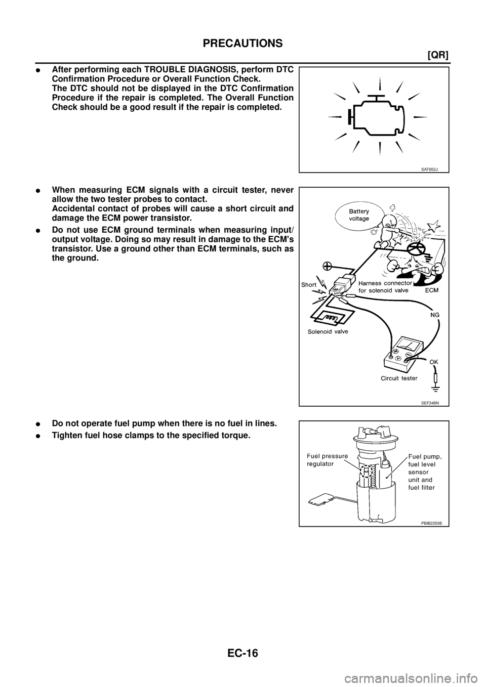
�When measuring ECM signals with a circuit tester, never
allow the two tester probes to contact.
Accidental contact of probes will cause a short circuit and
damage the ECM power transistor.
�Do not use ECM ground terminals when measuring input/
output voltage. Doing so may result in damage to the ECM's
transistor. Use a ground other than ECM terminals, such as
the ground.
�Do not operate fuel pump when there is no fuel in lines.
�Tighten fuel hose clamps to the specified torque.
SAT652J
SEF348N
PBIB2259E
Page 1333 of 3502
![NISSAN TEANA 2003 Service Manual BASIC SERVICE PROCEDURE
EC-51
[QR]
C
D
E
F
G
H
I
J
K
L
MA
EC
4. Install the fuel pressure gauge as shown in the figure.
�Wipe off oil or dirt from hose insertion part using cloth moist-
ened with ga](/manual-img/5/57392/w960_57392-1332.png "NISSAN TEANA 2003 Service Manual BASIC SERVICE PROCEDURE
EC-51
[QR]
C
D
E
F
G
H
I
J
K
L
MA
EC
4. Install the fuel pressure gauge as shown in the figure.
�Wipe off oil or dirt from hose insertion part using cloth moist-
ened with ga")
BASIC SERVICE PROCEDURE
EC-51
[QR]
C
D
E
F
G
H
I
J
K
L
MA
EC
4. Install the fuel pressure gauge as shown in the figure.
�Wipe off oil or dirt from hose insertion part using cloth moist-
ened with gasoline.
�Apply proper amount of gasoline between top of the fuel tube
and No.1 spool.
�Insert fuel hose for fuel pressure check until it touches the
No.1 spool on fuel tube.
�Use NISSAN genuine hose clamp (part number: 16439
N4710 or 16439 40U00).
�When reconnecting fuel line, always use new clamps.
�When reconnecting fuel hose, check the original fuel hose for
damage and abnormality.
�Use a torque driver to tighten clamps.
�Install hose clamp to the position within 1 - 2 mm (0.04 - 0.08
in).
�Make sure that clamp screw does not contact adjacent parts.
5. After connecting fuel hose for fuel pressure check, pull the hose
with a force of approximately 98 N (10 kg, 22 lb) to confirm fuel
tube does not come off.
6. Turn ignition switch ON, and check for fuel leakage.
7. Start engine and check for fuel leakage.
8. Read the indication of fuel pressure gauge.
�Do not perform fuel pressure check with system operating. Fuel pressure gauge may indicate false
readings.
�During fuel pressure check, confirm for fuel leakage from fuel connection every 3 minutes.
9. If result is unsatisfactory, go to next step.
10. Check the following.
�Fuel hoses and fuel tubes for clogging
�Fuel filter for clogging
�Fuel pump
�Fuel pressure regulator for clogging
If OK, replace fuel pressure regulator.
If NG, repair or replace.Tightening
torque:1 - 1.5 N·m (0.1 - 0.15 kg-m, 9 - 13 in-lb)
At idling: Approximately 350 kPa (3.5 bar, 3.57 kg/cm
2 , 51 psi)
PBIB0669E
PBIB1977E
Page 1398 of 3502
![NISSAN TEANA 2003 Service Manual EC-116
[QR]
DTC P0011 IVT CONTROL
DTC P0011 IVT CONTROLPFP:23796
DescriptionBBS005CP
SYSTEM DESCRIPTION
*: This signal is sent to the ECM through CAN communication line.
This mechanism hydraulically](/manual-img/5/57392/w960_57392-1397.png "NISSAN TEANA 2003 Service Manual EC-116
[QR]
DTC P0011 IVT CONTROL
DTC P0011 IVT CONTROLPFP:23796
DescriptionBBS005CP
SYSTEM DESCRIPTION
*: This signal is sent to the ECM through CAN communication line.
This mechanism hydraulically")
EC-116
[QR]
DTC P0011 IVT CONTROL
DTC P0011 IVT CONTROLPFP:23796
DescriptionBBS005CP
SYSTEM DESCRIPTION
*: This signal is sent to the ECM through CAN communication line.
This mechanism hydraulically controls cam phases continuously with the fixed operating angle of the intake
valve.
The ECM receives signals such as crankshaft position, camshaft position, engine speed, and engine coolant
temperature. Then, the ECM sends ON/OFF pulse duty signals to the intake valve timing control solenoid
valve depending on driving status. This makes it possible to control the shut/open timing of the intake valve to
increase engine torque in low/mid speed range and output in high-speed range.
COMPONENT DISCRIPTION
Intake valve timing control solenoid valve is activated by ON/OFF
pulse duty (ratio) signals from the ECM.
The intake valve timing control solenoid valve changes the oil
amount and direction of flow through intake valve timing control unit
or stops oil flow.
The longer pulse width advances valve angle.
The shorter pulse width retards valve angle.
When ON and OFF pulse widths become equal, the solenoid valve
stops oil pressure flow to fix the intake valve angle at the control
position.
CONSULT-II Reference Value in Data Monitor ModeBBS005CQ
Specification data are reference values.
Sensor Input signal to ECM ECM function Actuator
Crankshaft position sensor (POS)
Camshaft position sensor (PHASE)Engine speed
Intake valve
timing controlIntake valve timing control
solenoid valve Engine coolant temperature sensor Engine coolant temperature
Wheel sensor Vehicle speed*
PBIB3278E
PBIB1842E
MONITOR ITEM CONDITION SPECIFICATION
INT/V TIM (B1)
�Engine: After warming up
�Air conditioner switch: OFF
�Shift lever: N
�No loadIdle−5° - 5°CA
2,000 rpm Approx. 0° - 20°CA
Page 1429 of 3502
![NISSAN TEANA 2003 Service Manual DTC P0132 HO2S1
EC-147
[QR]
C
D
E
F
G
H
I
J
K
L
MA
EC
2. RETIGHTEN HEATED OXYGEN SENSOR 1
Loosen and retighten heated oxygen sensor 1.
>> GO TO 3.
3. CHECK HO2S1 GROUND CIRCUIT FOR OPEN AND SHORT
1.](/manual-img/5/57392/w960_57392-1428.png "NISSAN TEANA 2003 Service Manual DTC P0132 HO2S1
EC-147
[QR]
C
D
E
F
G
H
I
J
K
L
MA
EC
2. RETIGHTEN HEATED OXYGEN SENSOR 1
Loosen and retighten heated oxygen sensor 1.
>> GO TO 3.
3. CHECK HO2S1 GROUND CIRCUIT FOR OPEN AND SHORT
1.")
DTC P0132 HO2S1
EC-147
[QR]
C
D
E
F
G
H
I
J
K
L
MA
EC
2. RETIGHTEN HEATED OXYGEN SENSOR 1
Loosen and retighten heated oxygen sensor 1.
>> GO TO 3.
3. CHECK HO2S1 GROUND CIRCUIT FOR OPEN AND SHORT
1. Disconnect heated oxygen sensor 1 harness connector.
2. Disconnect ECM harness connector.
3. Check harness continuity between ECM terminal 74 and HO2S1
terminal 4.
Refer to Wiring Diagram.
4. Also check harness for short to ground and short to power.
OK or NG
OK >> GO TO 4.
NG >> Repair open circuit or short to ground or short to power
in harness or connectors.
4. CHECK HO2S1 INPUT SIGNAL CIRCUIT FOR OPEN AND SHORT
1. Check harness continuity between ECM terminal 35 and HO2S1 terminal 1.
Refer to Wiring Diagram.
2. Check harness continuity between ECM terminal 35 or HO2S1 terminal 1 and ground.
Refer to Wiring Diagram.
3. Also check harness for short to power.
OK or NG
OK >> GO TO 5.
NG >> Repair open circuit or short to ground or short to power in harness or connectors.
5. CHECK HO2S1 CONNECTOR FOR WATER
Check heated oxygen sensor 1 connectors for water.
OK or NG
OK >> GO TO 6.
NG >> Repair or replace harness or connectors.Tightening torque: 40 - 60 N·m (4.1 - 6.2 kg-m, 30 - 44 ft-lb)
PBIB2135E
Continuity should exist.
PBIB2136E
Continuity should exist.
Continuity should not exist.
Water should not exist.
Page 1636 of 3502
EC-354
[VQ]
PRECAUTIONS
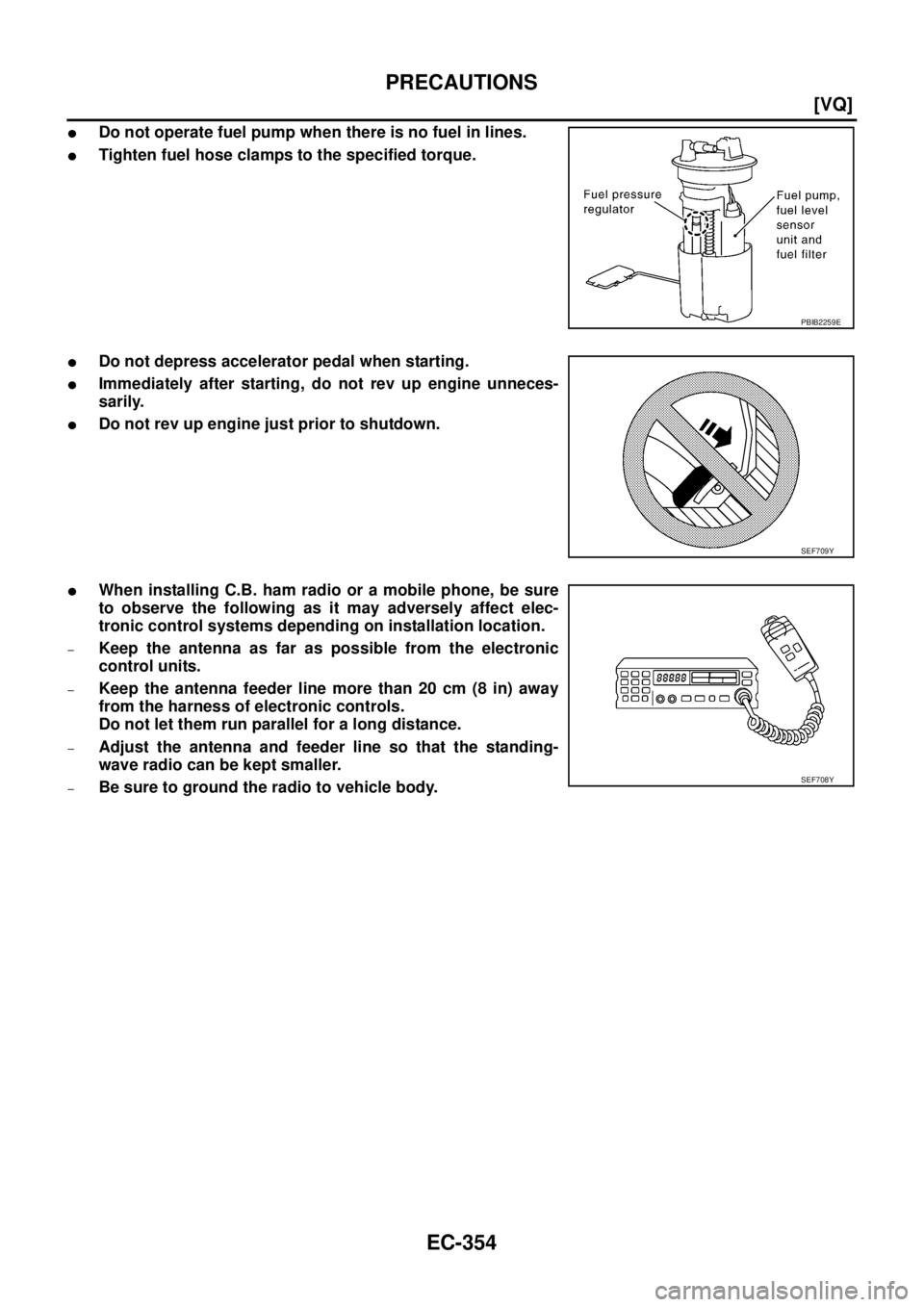
�Do not operate fuel pump when there is no fuel in lines.
�Tighten fuel hose clamps to the specified torque.
�Do not depress accelerator pedal when starting.
�Immediately after starting, do not rev up engine unneces-
sarily.
�Do not rev up engine just prior to shutdown.
�When installing C.B. ham radio or a mobile phone, be sure
to observe the following as it may adversely affect elec-
tronic control systems depending on installation location.
–Keep the antenna as far as possible from the electronic
control units.
–Keep the antenna feeder line more than 20 cm (8 in) away
from the harness of electronic controls.
Do not let them run parallel for a long distance.
–Adjust the antenna and feeder line so that the standing-
wave radio can be kept smaller.
–Be sure to ground the radio to vehicle body.
PBIB2259E
SEF709Y
SEF708Y

CVT-199
D
E
F
G
H
I
J
K
L
MA
B
CVT
CVT Fluid Temperature SensorBCS001N6
Primary Speed SensorBCS001N7
Secondary Speed SensorBCS001N8
Removal and InstallationBCS0")