Page 3222 of 3502

SC-4
BATTERY
BATTERYPFP:AYBGL
How to Handle Battery BKS001MB
CAUTION:
�If it becomes necessary to start the engine with a booster battery and jumper cables, use a 12-volt
booster battery.
�After connecting battery cables, ensure that they are tightly clamped to battery terminals for good
contact.
�Never add distilled water through the hole used to check specific gravity.
METHODS OF PREVENTING OVER-DISCHARGE
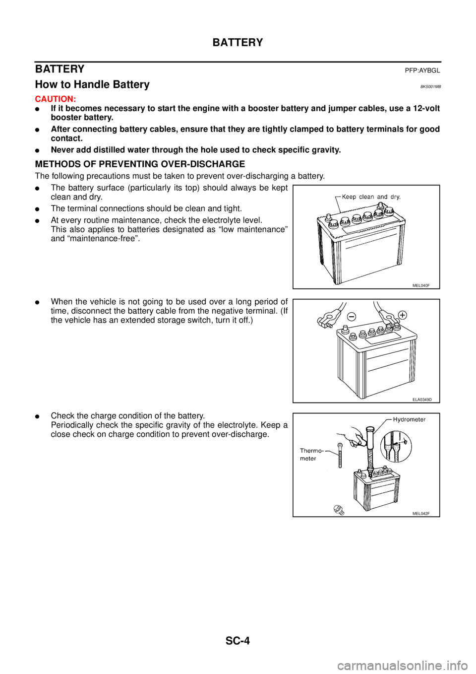
The following precautions must be taken to prevent over-discharging a battery.
�The battery surface (particularly its top) should always be kept
clean and dry.
�The terminal connections should be clean and tight.
�At every routine maintenance, check the electrolyte level.
This also applies to batteries designated as “low maintenance”
and “maintenance-free”.
�When the vehicle is not going to be used over a long period of
time, disconnect the battery cable from the negative terminal. (If
the vehicle has an extended storage switch, turn it off.)
�Check the charge condition of the battery.
Periodically check the specific gravity of the electrolyte. Keep a
close check on charge condition to prevent over-discharge.
MEL040F
ELA0349D
MEL042F
Page 3232 of 3502

SC-14
STARTING SYSTEM
STARTING SYSTEMPFP:23300
System Description BKS001ME
Power is supplied at all times:
�through 40A fusible link (letter F , located in the fuse and fusible link block)
�to ignition switch terminal 1,
�through 15A fuse (No. 71, located in the IPDM E/R)
�to CPU of IPDM E/R,
�through 15A fuse (No. 78, located in the IPDM E/R)
�to CPU of IPDM E/R.
With the ignition switch in the ON or START position, power is supplied:
[A/T models]
�from ignition relay
�through 10A fuse (No. 83, located in the IPDM E/R)
�through IPDM E/R terminal 26
�to park/neutral position switch terminal 1.
[CVT models]
�through ignition relay ( within the IPDM E/R )
�to CPU of IPDM E/R.
When the selector lever in the “P” or “N” position, power is supplied:
[A/T models]
�through park/neutral position switch terminal 2
�to IPDM E/R terminal 53.
[CVT models]
�from TCM terminal 24
�to IPDM E/R terminal 53.
Ground is supplied:
�to IPDM E/R terminals 38, 50 and 60
�from grounds E1 and E31.
Then starter relay is turn ON.
With the ignition switch in the START position, IPDM E/R is energized and power is supplied:
�from ignition switch terminal 5
�to IPDM E/R terminal 4 and
�through IPDM E/R terminal 3
�to starter motor terminal 1.
The starter motor plunger closes and provides a closed circuit between the battery and starter motor. The
starter motor is grounded to the engine block. With power and ground supplied, cranking occurs and the
engine starts.
Page 3245 of 3502

CHARGING SYSTEM
SC-27
C
D
E
F
G
H
I
J
L
MA
B
SC
CHARGING SYSTEMPFP:23100
System DescriptionBKS001MJ
The alternator provides DC voltage to operate the vehicle's electrical system and to keep the battery charged.
The voltage output is controlled by the IC regulator.
Power is supplied at all times:
�through 10A fuse (No. 36, located in the fuse and fusible link block)
�to alternator terminal 4 (“S” terminal).
“B” terminal supplies power to charge the battery and operate the vehicle's electrical system. Output voltage is
controlled by the IC regulator at terminal 4 (“S” terminal) detecting the input voltage.
The charging circuit is protected by the 120A fusible link (letter A, located in the fusible link holder).
The alternator is grounded to the engine block.
With the ignition switch in the ON or START position, power is supplied:
�through 10A fuse [No. 14, located in the fuse block (J/B)]
�to combination meter terminal 8 for the charge warning lamp.
Ground is supplied:
�to combination meter terminal 22
�through alternator terminal 3 (“L” terminal)
�to alternator terminal “E”
�through ground E2.
The charge warning lamp will illuminate. When the alternator is providing sufficient voltage with the engine
running, the ground is opened and the charge warning lamp will go off.
If the charge warning lamp illuminates with the engine running, a malfunction is indicated.
MALFUNCTION INDICATOR
The IC regulator warning function activates to illuminate charge warning lamp, if any of the following symp-
toms occur while alternator is operating:
�Excessive voltage is produced.
�No voltage is produced.
Page 3248 of 3502
SC-30
CHARGING SYSTEM
Removal and InstallationBKS0027E
VQ23DE AND VQ35DE MODELS
Removal
1. Disconnect negative battery cable.
2. Remove engine undercover, using power tools.
3. Remove radiator. Refer to CO-37, "
RADIATOR" in “ENGINE COOLING SYSTEM (CO)” section.
4. Remove alternator and air conditioner compressor belt. Refer to EM-129, "
Removal and Installation" in
“ENGINE MECHANICAL (EM)” section.
5. Remove idler pulley.
6. Remove alternator mounting nut, using power tools.
7. Remove through bolt.
8. Disconnect alternator connector.
9. Remove B terminal nut.
10. Remove ground harness clip and ground harness mounting nut.
1. Through-bolt 2. Cylinder block 3. Timing chain case
4. Alternator mounting nut 5. Alternator 6. Alternator connector
7. B terminal harness 8. B terminal nut 9. Alternator mounting bolt
10. Alternator bracket 11. Alternator bracket mounting bolt
PKIA2926J
PKIA2431E
PKIA2432E
Page 3249 of 3502
CHARGING SYSTEM
SC-31
C
D
E
F
G
H
I
J
L
MA
B
SC
11. Remove alternator mounting bolt, using power tools.
12. Remove alternator bracket mounting bolt and alternator bracket.
13. Remove alternator to the direction of upper side the vehicle.
Installation
Note the following, and install in the reverse order of removal.
�Install alternator, and check tension of belt. Refer to EM-128, "Checking Drive Belts" in “ENGINE
MECHANICAL (EM)” section.
CAUTION:
Be sure to tighten B terminal nut carefully.
PKIA2433E
Page 3250 of 3502
SC-32
CHARGING SYSTEM
QR20DE MODELS
Removal
1. Disconnect negative battery cable.
2. Remove drive belt. Refer to EM-14, "
Removal and Installation" .
3. Remove IPDM E/R bracket mounting bolts.
4. Slide IPDM E/R to the direction of arrow.
5. Disconnect alternator connector.
6. Remove B terminal nut.
7. Remove ground harness clip and ground harness bolt.
8. Remove alternator mounting bolts, using power tools.
9. Remove alternator to the direction of upper side the vehicle.
Installation
Note the following, and install in the reverse order of removal.
�Install alternator, and check tension of belt. Refer to EM-14, "Checking Drive Belts" in “ENGINE
MECHANICAL (EM)” section.
CAUTION:
Be sure to tighten B terminal nut carefully.
1. Alternator bracket 2. Alternator mounting bolt (upper) 3. Alternator mounting bolt (lower)
4. Alternator 5. B terminal harness 6. B terminal nut
7. Alternator connector
PKIA2930J
PKIA4811E
PKIA4812E
Page 3261 of 3502
PREPARATION
SE-5
C
D
E
F
G
H
J
K
L
MA
B
SE
PREPARATIONPFP:00002
Commercial Service ToolsBIS0012C
Tool name Description
Engine ear Locating the noise
SIIA0995E
Page 3263 of 3502

SQUEAK AND RATTLE TROUBLE DIAGNOSES
SE-7
C
D
E
F
G
H
J
K
L
MA
B
SE
DUPLICATE THE NOISE AND TEST DRIVE
If possible, drive the vehicle with the customer until the noise is duplicated. Note any additional information on
the Diagnostic Worksheet regarding the conditions or location of the noise. This information can be used to
duplicate the same conditions when you confirm the repair.
If the noise can be duplicated easily during the test drive, to help identify the source of the noise, try to dupli-
cate the noise with the vehicle stopped by doing one or all of the following:
1) Close a door.
2) Tap or push/pull around the area where the noise appears to be coming from.
3) Rev the engine.
4) Use a floor jack to recreate vehicle “twist”.
5) At idle, apply engine load (electrical load, half-clutch on M/T model, drive position on A/T model).
6) Raise the vehicle on a hoist and hit a tire with a rubber hammer.
�Drive the vehicle and attempt to duplicate the conditions the customer states exist when the noise occurs.
�If it is difficult to duplicate the noise, drive the vehicle slowly on an undulating or rough road to stress the
vehicle body.
CHECK RELATED SERVICE BULLETINS
After verifying the customer concern or symptom, check ASIST for Technical Service Bulletins (TSBs) related
to that concern or symptom.
If a TSB relates to the symptom, follow the procedure to repair the noise.
LOCATE THE NOISE AND IDENTIFY THE ROOT CAUSE
1. Narrow down the noise to a general area. To help pinpoint the source of the noise, use a listening tool
(Engine Ear or mechanics stethoscope).
2. Narrow down the noise to a more specific area and identify the cause of the noise by:
�removing the components in the area that you suspect the noise is coming from.
Do not use too much force when removing clips and fasteners, otherwise clips and fastener can be broken
or lost during the repair, resulting in the creation of new noise.
�tapping or pushing/pulling the component that you suspect is causing the noise.
Do not tap or push/pull the component with excessive force, otherwise the noise will be eliminated only
temporarily.
�feeling for a vibration with your hand by touching the component(s) that you suspect is (are) causing the
noise.
�placing a piece of paper between components that you suspect are causing the noise.
�looking for loose components and contact marks.
Refer to EI-7, "
Generic Squeak and Rattle Troubleshooting" .
REPAIR THE CAUSE
�If the cause is a loose component, tighten the component securely.
�If the cause is insufficient clearance between components:
–separate components by repositioning or loosening and retightening the component, if possible.
–insulate components with a suitable insulator such as urethane pads, foam blocks, felt cloth tape or ure-
thane tape are available through your authorized Nissan Parts Department.
CAUTION:
Do not use excessive force as many components are constructed of plastic and may be damaged.
NOTE:
Always check with the Parts Department for the latest parts information.
Each item can be ordered separately as needed.
URETHANE PADS [1.5 mm (0.059 in) thick]
Insulates connectors, harness, etc.
76268-9E005: 100 × 135 mm (3.94 × 5.31 in)/76884-71L01: 60 × 85 mm (2.36 × 3.35 in)/76884-71L02: 15 ×
25 mm (0.59 × 0.98 in)
INSULATOR (Foam blocks)
Insulates components from contact. Can be used to fill space behind a panel.
73982-9E000: 45 mm (1.77 in) thick, 50 × 50 mm (1.97 × 1.97 in)/73982-50Y00: 10 mm (0.39 in) thick, 50
× 50 mm (1.97 × 1.97 in)
INSULATOR (Light foam block)
80845-71L00: 30 mm (1.18 in) thick, 30 × 50 mm (1.18 × 1.97 in)