Page 3085 of 3502
HARNESS
PG-51
C
D
E
F
G
H
I
J
L
MA
B
PG
ENGINE CONTROL HARNESS(VQ ENGINE)
TKIM0668E
Page 3087 of 3502
HARNESS
PG-53
C
D
E
F
G
H
I
J
L
MA
B
PG
ENGINE CONTROL HARNESS(QR ENGINE)
TKIM0670E
Page 3097 of 3502

HARNESS
PG-63
C
D
E
F
G
H
I
J
L
MA
B
PG
Wiring Diagram Codes (Cell Codes) BKS002FS
Use the chart below to find out what each wiring diagram code stands for.
Refer to the wiring diagram code in the alphabetical index to find the location (page number) of each wiring
diagram.
Code Section Wiring Diagram Name
A/C ATC Air Conditioner
ABS BRC Anti-Lock Brake System
AFS LT Adaptive Front Lighting System
APPS1 EC Accelerator Pedal Position Sensor
APPS2 EC Accelerator Pedal Position Sensor
APPS3 EC Accelerator Pedal Position Sensor
ASC/BS EC Automatic Speed Control Device (ASCD) Brake Switch
ASC/SW EC Automatic Speed Control Device (ASCD) Steering Switch
ASCBOF EC Automatic Speed Control Device (ASCD) Brake Switch
ASCIND EC Automatic Speed Control Device (ASCD) Indicator
AT/IND DI A/T Indicator Lamp
AUDIO AV Audio
AUT/DP SE Automatic Drive Positioner
AUTO/L LT Auto Light Control
BA/FTS AT A/T Fluid Temperature Sensor and TCM Power Supply
BACK/L LT Back-Up Lamp
BRK/SW EC Brake Switch
CAN AT CAN Communication Line
CAN CVT CAN Communication Line
CAN EC CAN Communication Line
CAN LAN CAN System
CHARGE SC Charging System
CHIME DI Warning Chime
CIGAR WW Cigarette Lighter
COMBSW LT Combination Switch
COMM AV Audio Visual Communication Line
COOL/F EC Cooling Fan Control
CVTIND DI CVT Indicator Lamp
D/LOCK BL Power Door Lock
DEF GW Rear Window Defogger
ECM/PW EC ECM Power Supply for Back-Up
ECTS EC Engine Coolant Temperature Sensor
EMNT EC Electronic Controlled Engine Mount
ENGSS AT Engine Speed Signal
ETC1 EC Electric Throttle Control Function
ETC2 EC Electric Throttle Control Motor Relay
ETC3 EC Electric Throttle Control Motor
F/FOG LT Front Fog Lamp
F/LID BL Fuel Lid Opener
F/PUMP EC Fuel Pump
FRO2 EC Heated Oxygen Sensor 1 Heater
Page 3101 of 3502
ELECTRICAL UNITS LOCATION
PG-67
C
D
E
F
G
H
I
J
L
MA
B
PG
ELECTRICAL UNITS LOCATIONPFP:25230
Electrical Units Location BKS00251
ENGINE COMPARTMENT
CKIM0363E
Page 3121 of 3502

POWER STEERING FLUID
PS-7
C
D
E
F
H
I
J
K
L
MA
B
PS
POWER STEERING FLUIDPFP:KLF20
Checking Fluid LevelBGS0003P
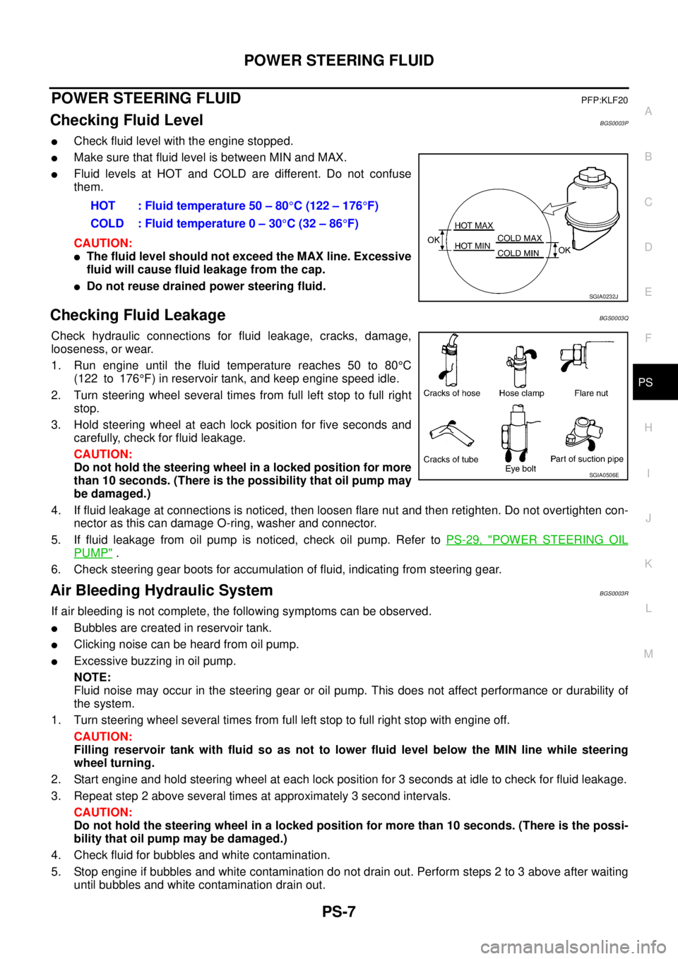
�Check fluid level with the engine stopped.
�Make sure that fluid level is between MIN and MAX.
�Fluid levels at HOT and COLD are different. Do not confuse
them.
CAUTION:
�The fluid level should not exceed the MAX line. Excessive
fluid will cause fluid leakage from the cap.
�Do not reuse drained power steering fluid.
Checking Fluid LeakageBGS0003Q
Check hydraulic connections for fluid leakage, cracks, damage,
looseness, or wear.
1. Run engine until the fluid temperature reaches 50 to 80°C
(122 to 176°F) in reservoir tank, and keep engine speed idle.
2. Turn steering wheel several times from full left stop to full right
stop.
3. Hold steering wheel at each lock position for five seconds and
carefully, check for fluid leakage.
CAUTION:
Do not hold the steering wheel in a locked position for more
than 10 seconds. (There is the possibility that oil pump may
be damaged.)
4. If fluid leakage at connections is noticed, then loosen flare nut and then retighten. Do not overtighten con-
nector as this can damage O-ring, washer and connector.
5. If fluid leakage from oil pump is noticed, check oil pump. Refer to PS-29, "
POWER STEERING OIL
PUMP" .
6. Check steering gear boots for accumulation of fluid, indicating from steering gear.
Air Bleeding Hydraulic SystemBGS0003R
If air bleeding is not complete, the following symptoms can be observed.
�Bubbles are created in reservoir tank.
�Clicking noise can be heard from oil pump.
�Excessive buzzing in oil pump.
NOTE:
Fluid noise may occur in the steering gear or oil pump. This does not affect performance or durability of
the system.
1. Turn steering wheel several times from full left stop to full right stop with engine off.
CAUTION:
Filling reservoir tank with fluid so as not to lower fluid level below the MIN line while steering
wheel turning.
2. Start engine and hold steering wheel at each lock position for 3 seconds at idle to check for fluid leakage.
3. Repeat step 2 above several times at approximately 3 second intervals.
CAUTION:
Do not hold the steering wheel in a locked position for more than 10 seconds. (There is the possi-
bility that oil pump may be damaged.)
4. Check fluid for bubbles and white contamination.
5. Stop engine if bubbles and white contamination do not drain out. Perform steps 2 to 3 above after waiting
until bubbles and white contamination drain out.HOT : Fluid temperature 50 – 80°C (122 – 176°F)
COLD : Fluid temperature 0 – 30°C (32 – 86°F)
SGIA0232J
SGIA0506E
Page 3122 of 3502
PS-8
POWER STEERING FLUID
6. Stop the engine, and then check fluid level.
Page 3123 of 3502

STEERING WHEEL
PS-9
C
D
E
F
H
I
J
K
L
MA
B
PS
STEERING WHEELPFP:48430
On-Vehicle Inspection and ServiceBGS0003S
CHECKING CONDITION OF INSTALLATION
�Check installation conditions of steering gear assembly, front suspension assembly, axle and steering col-
umn assembly.
�Check if movement exists when steering wheel is moved up and down, to the left and right and to the axial
direction.
�Check steering gear assembly mounting nut and bolts for looseness. Refer to PS-17, "COMPONENTS" .
CHECKING STEERING WHEEL PLAY
�Turn steering wheel so that front wheels come to the straight-ahead position. Start engine and lightly turn
steering wheel to the left and right until front wheels start to move. Measure steering wheel movement on
the outer circumference.
�When the measurement value is outside the standard value, check backlash for each joint of steering col-
umn assembly and installation condition of power steering gear assembly.
CHECKING NEUTRAL POSITION STEERING WHEEL
�Make sure that steering gear assembly, steering column and steering wheel are installed in the correct
position.
�Perform neutral position inspection after wheel alignment. Refer to FSU-5, "Wheel Alignment Inspection" .
�Set vehicle to the straight-ahead position and confirm steering wheel is in the neutral position.
�Loosen outer socket lock nut and turn inner socket to left and right equally to make fine adjustments if
steering wheel is not in the neutral position.
CHECKING STEERING WHEEL TURNING FORCE
1. Park vehicle on a level and dry surface, set parking brake.
2. Start engine.
3. Bring power steering fluid up to adequate operating temperature. [Make sure temperature of fluid is
approximately 50 to 80°C (122 to 176°F).]
NOTE:
Tires need to be inflated normal pressure.
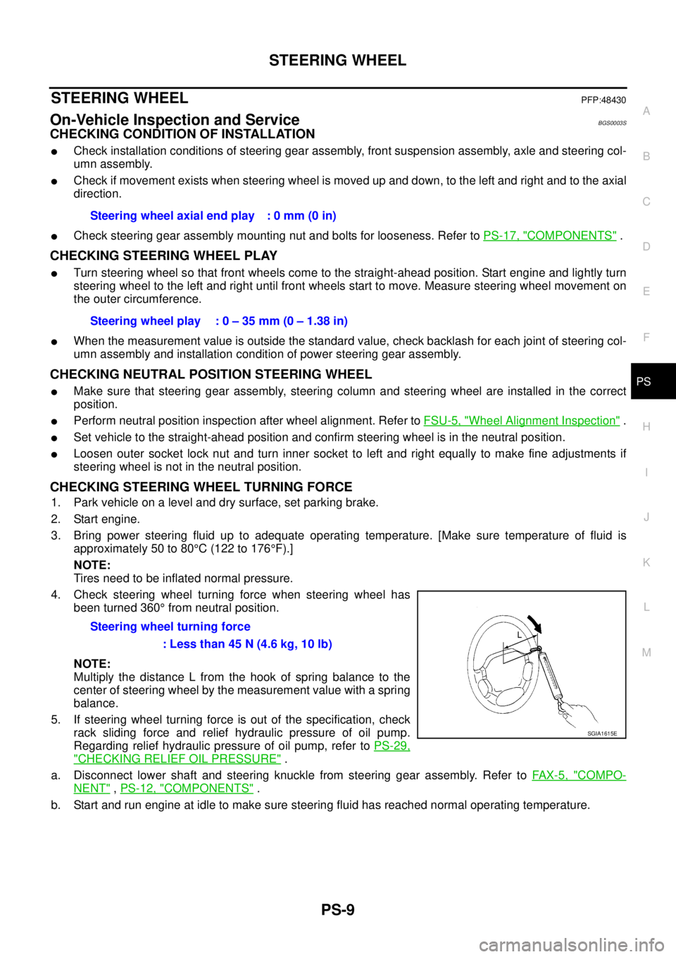
4. Check steering wheel turning force when steering wheel has
been turned 360° from neutral position.
NOTE:
Multiply the distance L from the hook of spring balance to the
center of steering wheel by the measurement value with a spring
balance.
5. If steering wheel turning force is out of the specification, check
rack sliding force and relief hydraulic pressure of oil pump.
Regarding relief hydraulic pressure of oil pump, refer to PS-29,
"CHECKING RELIEF OIL PRESSURE" .
a. Disconnect lower shaft and steering knuckle from steering gear assembly. Refer to FAX-5, "
COMPO-
NENT" , PS-12, "COMPONENTS" .
b. Start and run engine at idle to make sure steering fluid has reached normal operating temperature.Steering wheel axial end play : 0 mm (0 in)
Steering wheel play : 0 – 35 mm (0 – 1.38 in)
Steering wheel turning force
: Less than 45 N (4.6 kg, 10 lb)
SGIA1615E
Page 3124 of 3502

PS-10
STEERING WHEEL
c. While pulling outer socket slowly in ±11.5 mm (±0.453 in) range
from neutral position, make sure rack sliding force is within
specification.
d. If rack sliding force is not within specification, overhaul steering
gear assembly.
CHECKING FRONT WHEEL TURNING ANGLE
�Check front wheel turning angle after toe-in inspection. Place
front wheels on turning radius gauges and rear wheels on
stands. Check the maximum inner and outer wheel turning
angles for LH and RH road wheels.
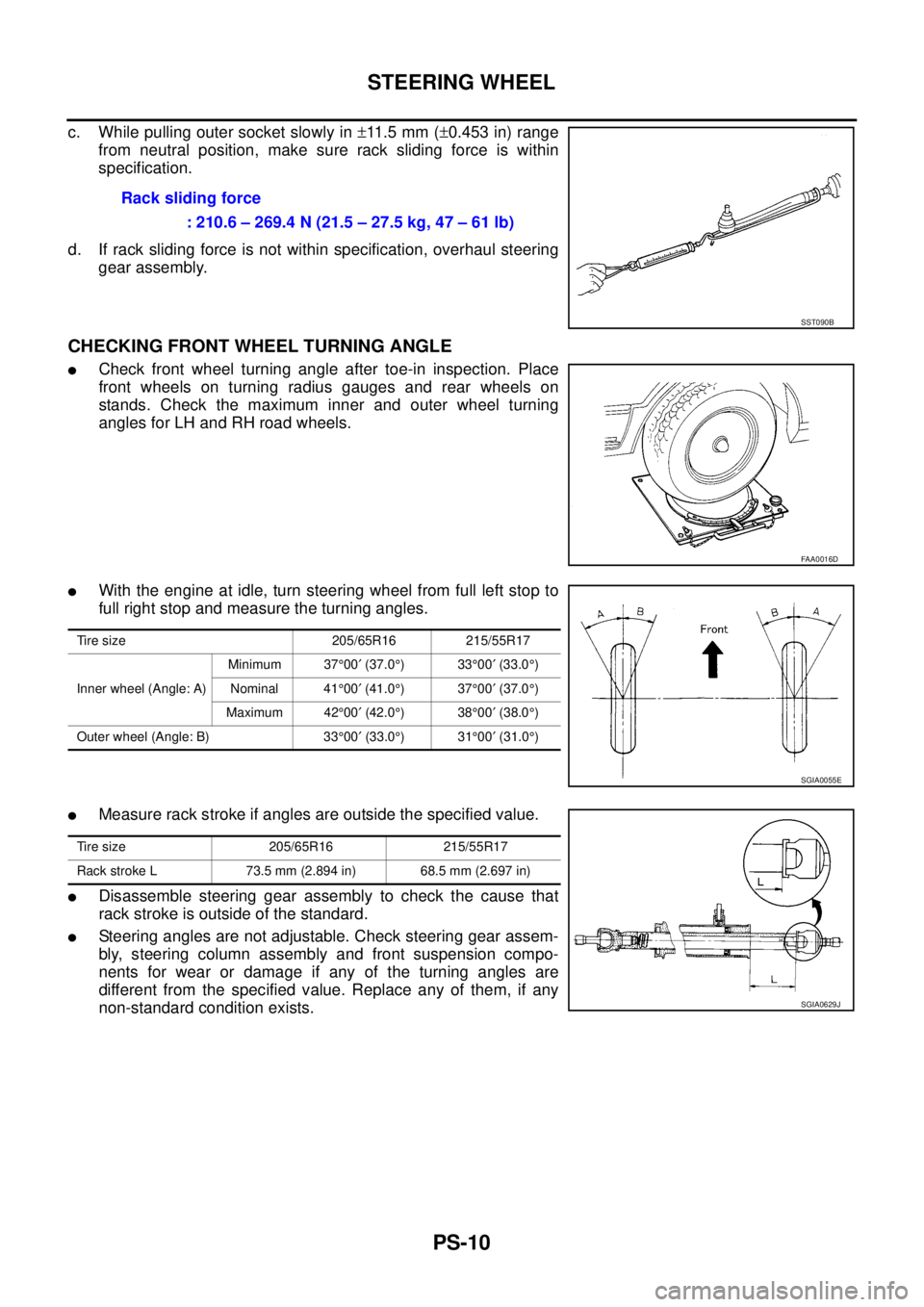
�With the engine at idle, turn steering wheel from full left stop to
full right stop and measure the turning angles.
�Measure rack stroke if angles are outside the specified value.
�Disassemble steering gear assembly to check the cause that
rack stroke is outside of the standard.
�Steering angles are not adjustable. Check steering gear assem-
bly, steering column assembly and front suspension compo-
nents for wear or damage if any of the turning angles are
different from the specified value. Replace any of them, if any
non-standard condition exists.Rack sliding force
: 210.6 – 269.4 N (21.5 – 27.5 kg, 47 – 61 lb)
SST090B
FAA0016D
Tire size 205/65R16 215/55R17
Inner wheel (Angle: A)Minimum 37°00′ (37.0°)33°00′ (33.0°)
Nominal 41°00′ (41.0°)37°00′ (37.0°)
Maximum 42°00′ (42.0°)38°00′ (38.0°)
Outer wheel (Angle: B) 33°00′ (33.0°)31°00′ (31.0°)
SGIA0055E
Tire size 205/65R16 215/55R17
Rack stroke L 73.5 mm (2.894 in) 68.5 mm (2.697 in)
SGIA0629J