Page 2371 of 3502
SERVICE DATA AND SPECIFICATIONS (SDS)
EM-263
[VQ]
C
D
E
F
G
H
I
J
K
L
MA
EM
*3 Machining data
Valve Spring
*: Exhaust side valve spring for VQ23DE has a parallel setting.Engine VQ23DE VQ35DE
Position Intake Exhaust* Intake Exhaust
Free height47.15 mm
(1.8563 in)52.28 mm
(2.0583 in)52.31 mm
(2.0594 in)47.07 mm
(1.8531 in)
Installation height37.00 mm
(1.4567 in)37.00 mm
(1.4567 in)37.00 mm
(1.4567 in)37.00 mm
(1.4567 in)
Installation load166 - 188 N
(16.9 - 19.2 kg,
37 - 42 lb)153 - 173 N
(15.6 - 17.6 kg,
34 - 39 lb)153 - 173 N
(15.6 - 17.6 kg,
34 - 39 lb)166 - 188 N
(16.9 - 19.2 kg,
37 - 42 lb)
Height during valve open27.20 mm
(1.0709 in)29.25 mm
(1.1516 in)29.25 mm
(1.1516 in)27.20 mm
(1.0709 in)
Load with valve open373 - 421 N
(38.0 - 42.9 kg,
84 - 95 lb)276 - 312 N
(28.1 - 31.8 kg,
62 - 70 lb)276 - 312 N
(28.1 - 31.8 kg,
62 - 70 lb)373 - 421 N
(38.0 - 42.9 kg,
84 - 95 lb)
Squareness 2.1 mm (0.083 in) 2.3 mm (0.091 in) 2.3 mm (0.091 in) 2.1 mm (0.083 in)
Page 2372 of 3502
![NISSAN TEANA 2003 Service Manual EM-264
[VQ]
SERVICE DATA AND SPECIFICATIONS (SDS)
CYLINDER BLOCK
Unit: mm (in)
EngineVQ23DE VQ35DE
Surface distortionStandard 0.03 (0.0012)
Limit 0.1 (0.004)
Main bearing housing inner diameter Stan](/manual-img/5/57392/w960_57392-2371.png "NISSAN TEANA 2003 Service Manual EM-264
[VQ]
SERVICE DATA AND SPECIFICATIONS (SDS)
CYLINDER BLOCK
Unit: mm (in)
EngineVQ23DE VQ35DE
Surface distortionStandard 0.03 (0.0012)
Limit 0.1 (0.004)
Main bearing housing inner diameter Stan")
EM-264
[VQ]
SERVICE DATA AND SPECIFICATIONS (SDS)
CYLINDER BLOCK
Unit: mm (in)
EngineVQ23DE VQ35DE
Surface distortionStandard 0.03 (0.0012)
Limit 0.1 (0.004)
Main bearing housing inner diameter Standard 63.993 - 64.017 (2.5194 - 2.5203)
Cylinder bore Inner diameterStandardGrade No. 185.000 - 85.010
(3.3465 - 3.3468)95.500 - 95.510
(3.7598 - 3.7602)
Grade No. 285.010 - 85.020
(3.3468 - 3.3472)95.510 - 95.520
(3.7602 - 3.7606)
Grade No. 385.020 - 85.030
(3.3472 - 3.3476)95.520 - 95.530
(3.7606 - 3.7610)
Wear limit 0.2 (0.008)
Out-of-round (Difference between “X” and “Y”)
Limit0.015 (0.0006)
Taper (Difference between “A” and “C”) 0.01 (0.0004)
Main bearing housing inner diameter (Without bearing)Grade No. A
Grade No. B
Grade No. C
Grade No. D
Grade No. E
Grade No. F
Grade No. G
Grade No. H
Grade No. J
Grade No. K
Grade No. L
Grade No. M
Grade No. N
Grade No. P
Grade No. R
Grade No. S
Grade No. T
Grade No. U
Grade No. V
Grade No. W
Grade No. X
Grade No. Y
Grade No. 4
Grade No. 763.993 - 63.994 (2.5194 - 2.5194)
63.994 - 63.995 (2.5194 - 2.5195)
63.995 - 63.996 (2.5195 - 2.5195)
63.996 - 63.997 (2.5195 - 2.5196)
63.997 - 63.998 (2.5196 - 2.5196)
63.998 - 63.999 (2.5196 - 2.5196)
63.999 - 64.000 (2.5196 - 2.5197)
64.000 - 64.001 (2.5197 - 2.5197)
64.001 - 64.002 (2.5197 - 2.5198)
64.002 - 64.003 (2.5198 - 2.5198)
64.003 - 64.004 (2.5198 - 2.5198)
64.004 - 64.005 (2.5198 - 2.5199)
64.005 - 64.006 (2.5199 - 2.5199)
64.006 - 64.007 (2.5199 - 2.5200)
64.007 - 64.008 (2.5200 - 2.5200)
64.008 - 64.009 (2.5200 - 2.5200)
64.009 - 64.010 (2.5200 - 2.5201)
64.010 - 64.011 (2.5201 - 2.5201)
64.011 - 64.012 (2.5201 - 2.5202)
64.012 - 64.013 (2.5202 - 2.5202)
64.013 - 64.014 (2.5202 - 2.5202)
64.014 - 64.015 (2.5202 - 2.5203)
64.015 - 64.016 (2.5203 - 2.5203)
64.016 - 64.017 (2.5203 - 2.5203)
Difference in inner diameter between cylinders Standard Less than 0.03 (0.0012)
PBIC0923E
Page 2375 of 3502
![NISSAN TEANA 2003 Service Manual SERVICE DATA AND SPECIFICATIONS (SDS)
EM-267
[VQ]
C
D
E
F
G
H
I
J
K
L
MA
EM
CRANKSHAFT
Unit: mm (in)
*: Total indicator readingEngineVQ23DE VQ35DE
Main journal diameter “Dm” StandardGrade No. A](/manual-img/5/57392/w960_57392-2374.png "NISSAN TEANA 2003 Service Manual SERVICE DATA AND SPECIFICATIONS (SDS)
EM-267
[VQ]
C
D
E
F
G
H
I
J
K
L
MA
EM
CRANKSHAFT
Unit: mm (in)
*: Total indicator readingEngineVQ23DE VQ35DE
Main journal diameter “Dm” StandardGrade No. A")
SERVICE DATA AND SPECIFICATIONS (SDS)
EM-267
[VQ]
C
D
E
F
G
H
I
J
K
L
MA
EM
CRANKSHAFT
Unit: mm (in)
*: Total indicator readingEngineVQ23DE VQ35DE
Main journal diameter “Dm” StandardGrade No. A
Grade No. B
Grade No. C
Grade No. D
Grade No. E
Grade No. F
Grade No. G
Grade No. H
Grade No. J
Grade No. K
Grade No. L
Grade No. M
Grade No. N
Grade No. P
Grade No. R
Grade No. S
Grade No. T
Grade No. U
Grade No. V
Grade No. W
Grade No. X
Grade No. Y
Grade No. 4
Grade No. 759.974 - 59.975 (2.3612 - 2.3612)
59.973 - 59.974 (2.3611 - 2.3612)
59.972 - 59.973 (2.3611 - 2.3611)
59.971 - 59.972 (2.3611 - 2.3611)
59.970 - 59.971 (2.3610 - 2.3611)
59.969 - 59.970 (2.3610 - 2.3610)
59.968 - 59.969 (2.3609 - 2.3610)
59.967 - 59.968 (2.3609 - 2.3609)
59.966 - 59.967 (2.3609 - 2.3609)
59.965 - 59.966 (2.3608 - 2.3609)
59.964 - 59.965 (2.3608 - 2.3608)
59.963 - 59.964 (2.3607 - 2.3608)
59.962 - 59.963 (2.3607 - 2.3607)
59.961 - 59.962 (2.3607 - 2.3607)
59.960 - 59.961 (2.3606 - 2.3607)
59.959 - 59.960 (2.3606 - 2.3606)
59.958 - 59.959 (2.3605 - 2.3606)
59.957 - 59.958 (2.3605 - 2.3605)
59.956 - 59.957 (2.3605 - 2.3605)
59.955 - 59.956 (2.3604 - 2.3605)
59.954 - 59.955 (2.3604 - 2.3604)
59.953 - 59.954 (2.3603 - 2.3604)
59.952 - 59.953 (2.3603 - 2.3603)
59.951 - 59.952 (2.3603 - 2.3603)
Pin journal diameter “Dp” StandardGrade No. 044.968 - 44.974
(1.7704 - 1.7706)51.968 - 51.974
(2.0460 - 2.0462)
Grade No. 144.962 - 44.968
(1.7702 - 1.7704)51.962 - 51.968
(2.0457 - 2.0460)
Grade No. 244.956 - 44.962
(1.7699 - 1.7702)51.956 - 51.962
(2.0455 - 2.0457)
Center distance “r”34.46 - 34.54
(1.3567 - 1.3598)40.66 - 40.74
(1.6008 - 1.6039)
Out-of-round (Difference between “X” and “Y”)
Limit0.002 (0.0001)
Taper (Difference between “A” and “B”) 0.002 (0.0001)
Crankshaft runout [TIR*]Standard Less than 0.05 (0.002)
Limit 0.1 (0.004)
Crankshaft end playStandard 0.10 - 0.25 (0.004 - 0.0098)
Limit 0.3 (0.02)
SEM645SBIA0535E
Page 2379 of 3502
EX-1
EXHAUST SYSTEM
B ENGINE
CONTENTS
C
D
E
F
G
H
I
J
K
L
M
SECTION EX
A
EX
EXHAUST SYSTEM
EXHAUST SYSTEM ................................................... 2Checking Exhaust System ........................................ 2
Removal and Installation .......................................... 2
REMOVAL ............................................................. 3
INSTALLATION ..................................................... 3
INSPECTION AFTER INSTALLATION .................. 4
Page 2380 of 3502
EX-2
EXHAUST SYSTEM
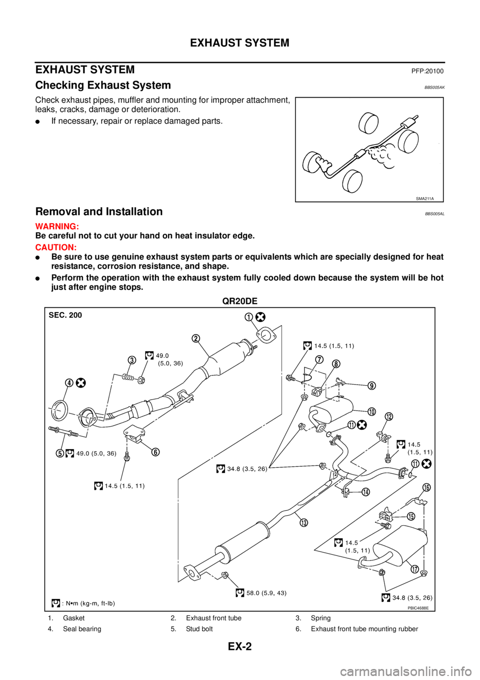
EXHAUST SYSTEMPFP:20100
Checking Exhaust SystemBBS005AK
Check exhaust pipes, muffler and mounting for improper attachment,
leaks, cracks, damage or deterioration.
�If necessary, repair or replace damaged parts.
Removal and InstallationBBS005AL
WARNING:
Be careful not to cut your hand on heat insulator edge.
CAUTION:
�Be sure to use genuine exhaust system parts or equivalents which are specially designed for heat
resistance, corrosion resistance, and shape.
�Perform the operation with the exhaust system fully cooled down because the system will be hot
just after engine stops.
QR20DE
SMA211A
PBIC4688E
1. Gasket 2. Exhaust front tube 3. Spring
4. Seal bearing 5. Stud bolt 6. Exhaust front tube mounting rubber
Page 2382 of 3502

EX-4
EXHAUST SYSTEM
�When installing heat insulator avoid large gaps or interference between heat insulator and each
exhaust pipe.
�Remove deposits from the sealing surface of each connection. Connect them securely to avoid
gas leakage.
�Temporarily tighten mounting nuts and bolts on the exhaust manifold side, and mounting bolts
and nuts on the vehicle side. Check each part for unusual interference, and then tighten them to
the specified torque.
�When installing each mounting rubber, avoid twisting or unusual extension in up/down and right/
left directions.
Seal Bearing (QR20DE)
1. Securely insert seal bearing into exhaust manifold and three
way catalyst assembly side in the direction as shown in the fig-
ure.
CAUTION:
Be careful not to damage seal bearing surface when install-
ing.
2. With spring large diameter side facing to exhaust front tube
flange, tighten mounting nut.
3. Make sure that stud bolt does not interfere with flange of
exhaust front tube.
INSPECTION AFTER INSTALLATION
�Make sure that clearance between tail tube and rear bumper is even.
�With engine running, check exhaust tube joints for gas leakage and unusual noises.
�Make sure that mounting brackets and mounting rubbers are installed properly and free from undue
stress. Improper installation could result in excessive noise and vibration.
PBIC2432E
Page 2391 of 3502

FRONT DRIVE SHAFT
FAX-9
C
E
F
G
H
I
J
K
L
MA
B
FA X
11. Remove circular clip from shaft.
12. Remove boot from shaft.
13. Clean the old grease on joint sub-assembly with paper towels.
14. Apply the appropriate amount of grease (NISSAN genuine
grease or equivalent) inside joint sub-assembly serration hole
until grease begins to ooze from ball groove and serration hole.
After inserting grease, use a shop cloth to wipe off old grease
that has oozed out.
15. Wrap serration on shaft with tape to protect boot from damage.
Install new boot and boot bands to shaft.
NOTE:
Do not reuse boot bands and boot.
16. Remove the tape wrapped around the serration on shaft.
17. Position circular clip on groove at shaft edge. Align both counter
axles of shaft edge and joint sub-assembly. Then, assemble
shaft with circular clip onto joint sub-assembly.
NOTE:
�Do not reuse circular clip.
�Drive joint inserter (suitable tool) is recommended when
installing circular clip.
18. Install joint sub-assembly to shaft using plastic hammer.
CAUTION:
Confirm that joint sub-assembly is correctly engaged while
rotating drive shaft.
19. Apply the balance of the specified amount of grease (NISSAN
genuine grease or equivalent) into boot inside from large diame-
ter side of boot.
SDIA2489E
SDIA2775E
SDIA2490E
Engine model Grease amount
QR20DE
88 – 108 g (3.10 – 3.80 oz)
VQ23DE
VQ35DE 115 – 125 g (4.06 – 4.41 oz)
SDIA2372E
Page 2392 of 3502
 shown in
the figure.
CAUTION:
If there is grease on boot mounting surfaces (indicated by *
marks) of shaft and")
FAX-10
FRONT DRIVE SHAFT
20. Install boot securely into grooves (indicated by *marks) shown in
the figure.
CAUTION:
If there is grease on boot mounting surfaces (indicated by *
marks) of shaft and housing, boot may come off. Remove
all grease from surfaces.
21. Make sure boot installation length “L” is the length indicated
below. Insert flat-bladed screwdriver or similar tool into smaller
side of boot. bleed air from boot to prevent boot deformation.
CAUTION:
�Boot may break if boot installation length is less then standard value.
�Take care not to touch the tip of screwdriver to inside of boot.
22. Secure the large and small ends of boot with new boot bands
using boot band crimping tool [SST: KV40107300] as shown in
the figure.
NOTE:
�Do not reuse boot bands.
�Secure boot band so that dimension “M” meets the specifica-
tion as shown.
23. Secure joint sub-assembly and shaft, and then make sure that
they are in the correct position when rotating boot. Install them
with new boot band when boot installation positions become
incorrect.
24. Confirm that circular clip on transaxle side is fully engaged.
25. Insert drive shaft to wheel hub and bearing assembly, and then
temporarily tighten hub lock nut.
26. Install nuts and bolts of steering knuckle and strut. Refer to FSU-7, "
Components" , “FRONT SUSPEN-
SION ASSEMBLY” for tightening torque.
27. Install disc rotor. Refer to FAX-5, "
Removal and Installation" .
28. Install torque member fixing bolts to steering knuckle. Refer to BR-26, "
FRONT DISC BRAKE" .
29. Install wheel sensor to steering knuckle. Refer to BRC-33, "
WHEEL SENSORS" .
30. Tighten lock nut to the specified torque. Refer to FA X - 11 , "
COMPONENT"
31. Install cotter pin.
NOTE:
Do not reuse cotter pin.
32. Install tires to vehicle.Engine model Boot installation length L
QR20DE
141.7 – 143.7 mm (5.58 – 5.66 in)
VQ23DE
VQ35DE 155.3 – 161.3 mm (6.11 – 6.35 in)
SDIA1760E
RAC1133D
Dimension “M” : 2.0 – 3.0 mm (0.079 – 0.118 in)
DSF0047D
![NISSAN TEANA 2003 Service Manual SERVICE DATA AND SPECIFICATIONS (SDS)
EM-263
[VQ]
C
D
E
F
G
H
I
J
K
L
MA
EM
*3 Machining data
Valve Spring
*: Exhaust side valve spring for VQ23DE has a parallel setting.Engine VQ23DE VQ35DE
Positio](/manual-img/5/57392/w960_57392-2370.png "NISSAN TEANA 2003 Service Manual SERVICE DATA AND SPECIFICATIONS (SDS)
EM-263
[VQ]
C
D
E
F
G
H
I
J
K
L
MA
EM
*3 Machining data
Valve Spring
*: Exhaust side valve spring for VQ23DE has a parallel setting.Engine VQ23DE VQ35DE
Positio")