2003 NISSAN ALMERA N16 differential
[x] Cancel search: differentialPage 1449 of 3189
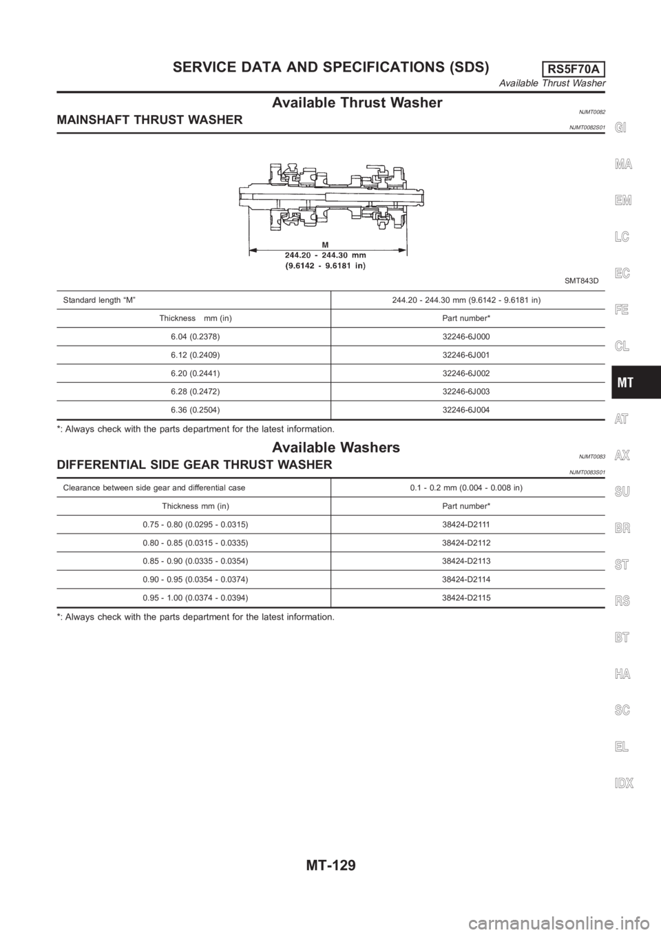
Available Thrust WasherNJMT0082MAINSHAFT THRUST WASHERNJMT0082S01
SMT843D
Standard length “M” 244.20 - 244.30 mm (9.6142 - 9.6181 in)
Thickness mm (in) Part number*
6.04 (0.2378) 32246-6J000
6.12 (0.2409) 32246-6J001
6.20 (0.2441) 32246-6J002
6.28 (0.2472) 32246-6J003
6.36 (0.2504) 32246-6J004
*: Always check with the parts department for the latest information.
Available WashersNJMT0083DIFFERENTIAL SIDE GEAR THRUST WASHERNJMT0083S01
Clearance between side gear and differential case 0.1 - 0.2 mm (0.004 - 0.008 in)
Thickness mm (in) Part number*
0.75 - 0.80 (0.0295 - 0.0315) 38424-D2111
0.80 - 0.85 (0.0315 - 0.0335) 38424-D2112
0.85 - 0.90 (0.0335 - 0.0354) 38424-D2113
0.90 - 0.95 (0.0354 - 0.0374) 38424-D2114
0.95 - 1.00 (0.0374 - 0.0394) 38424-D2115
*: Always check with the parts department for the latest information.
GI
MA
EM
LC
EC
FE
CL
AT
AX
SU
BR
ST
RS
BT
HA
SC
EL
IDX
SERVICE DATA AND SPECIFICATIONS (SDS)RS5F70A
Available Thrust Washer
MT-129
Page 1450 of 3189
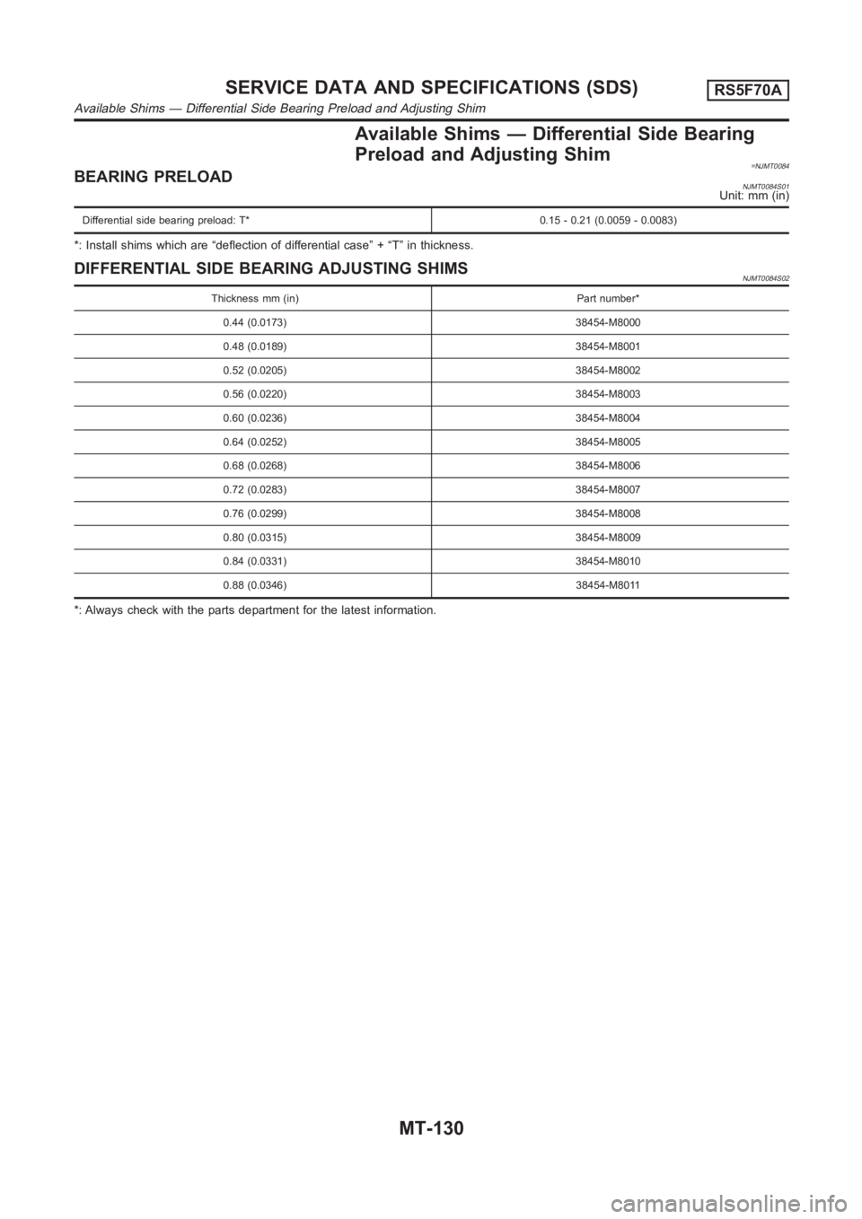
Available Shims — Differential Side Bearing
Preload and Adjusting Shim
=NJMT0084BEARING PRELOADNJMT0084S01Unit: mm (in)
Differential side bearing preload: T* 0.15 - 0.21 (0.0059 - 0.0083)
*: Install shims which are “deflection of differential case” + “T” in thickness.
DIFFERENTIAL SIDE BEARING ADJUSTING SHIMSNJMT0084S02
Thickness mm (in) Part number*
0.44 (0.0173) 38454-M8000
0.48 (0.0189) 38454-M8001
0.52 (0.0205) 38454-M8002
0.56 (0.0220) 38454-M8003
0.60 (0.0236) 38454-M8004
0.64 (0.0252) 38454-M8005
0.68 (0.0268) 38454-M8006
0.72 (0.0283) 38454-M8007
0.76 (0.0299) 38454-M8008
0.80 (0.0315) 38454-M8009
0.84 (0.0331) 38454-M8010
0.88 (0.0346) 38454-M8011
*: Always check with the parts department for the latest information.
SERVICE DATA AND SPECIFICATIONS (SDS)RS5F70A
Available Shims — Differential Side Bearing Preload and Adjusting Shim
MT-130
Page 1453 of 3189
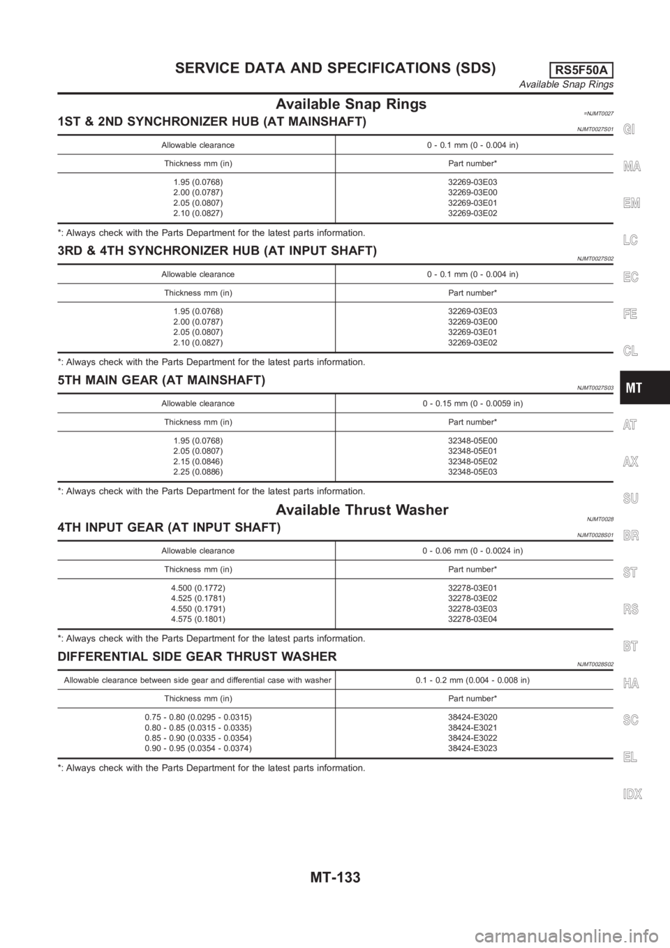
Available Snap Rings=NJMT00271ST & 2ND SYNCHRONIZER HUB (AT MAINSHAFT)NJMT0027S01
Allowable clearance 0 - 0.1 mm (0 - 0.004 in)
Thickness mm (in) Part number*
1.95 (0.0768)
2.00 (0.0787)
2.05 (0.0807)
2.10 (0.0827)32269-03E03
32269-03E00
32269-03E01
32269-03E02
*: Always check with the Parts Department for the latest parts information.
3RD & 4TH SYNCHRONIZER HUB (AT INPUT SHAFT)NJMT0027S02
Allowable clearance 0 - 0.1 mm (0 - 0.004 in)
Thickness mm (in) Part number*
1.95 (0.0768)
2.00 (0.0787)
2.05 (0.0807)
2.10 (0.0827)32269-03E03
32269-03E00
32269-03E01
32269-03E02
*: Always check with the Parts Department for the latest parts information.
5TH MAIN GEAR (AT MAINSHAFT)NJMT0027S03
Allowable clearance 0 - 0.15 mm (0 - 0.0059 in)
Thickness mm (in) Part number*
1.95 (0.0768)
2.05 (0.0807)
2.15 (0.0846)
2.25 (0.0886)32348-05E00
32348-05E01
32348-05E02
32348-05E03
*: Always check with the Parts Department for the latest parts information.
Available Thrust WasherNJMT00284TH INPUT GEAR (AT INPUT SHAFT)NJMT0028S01
Allowable clearance 0 - 0.06 mm (0 - 0.0024 in)
Thickness mm (in) Part number*
4.500 (0.1772)
4.525 (0.1781)
4.550 (0.1791)
4.575 (0.1801)32278-03E01
32278-03E02
32278-03E03
32278-03E04
*: Always check with the Parts Department for the latest parts information.
DIFFERENTIAL SIDE GEAR THRUST WASHERNJMT0028S02
Allowable clearance between side gear and differential case with washer 0.1 - 0.2 mm (0.004 - 0.008 in)
Thickness mm (in) Part number*
0.75 - 0.80 (0.0295 - 0.0315)
0.80 - 0.85 (0.0315 - 0.0335)
0.85 - 0.90 (0.0335 - 0.0354)
0.90 - 0.95 (0.0354 - 0.0374)38424-E3020
38424-E3021
38424-E3022
38424-E3023
*: Always check with the Parts Department for the latest parts information.
GI
MA
EM
LC
EC
FE
CL
AT
AX
SU
BR
ST
RS
BT
HA
SC
EL
IDX
SERVICE DATA AND SPECIFICATIONS (SDS)RS5F50A
Available Snap Rings
MT-133
Page 1454 of 3189
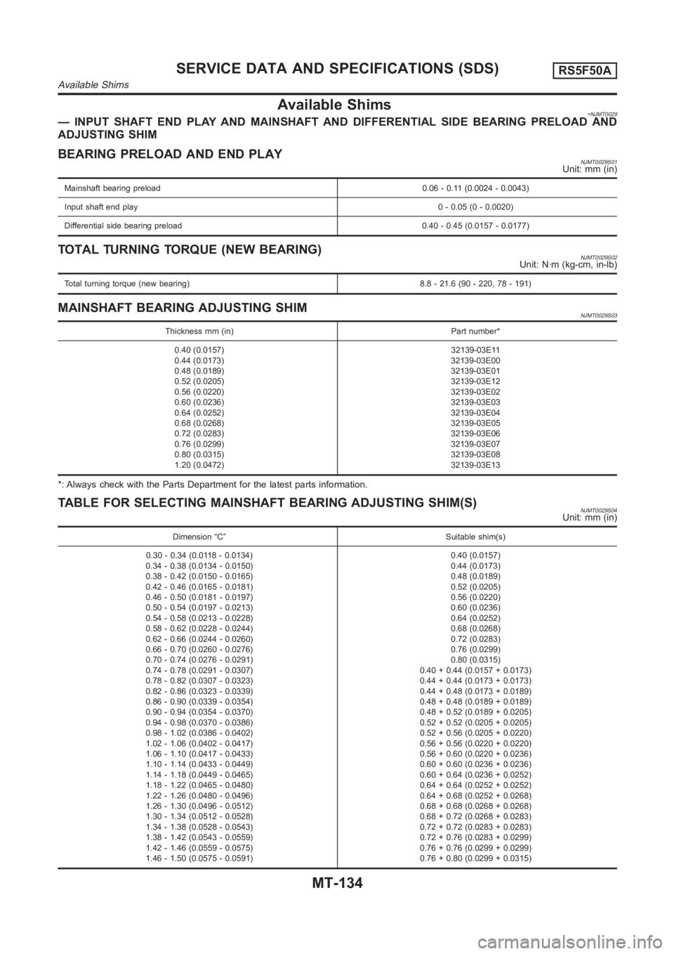
Available Shims=NJMT0029— INPUT SHAFT END PLAY AND MAINSHAFT AND DIFFERENTIAL SIDE BEARING PRELOADAND
ADJUSTING SHIM
BEARING PRELOAD AND END PLAYNJMT0029S01Unit: mm (in)
Mainshaft bearing preload 0.06 - 0.11 (0.0024 - 0.0043)
Input shaft end play0 - 0.05 (0 - 0.0020)
Differential side bearing preload 0.40 - 0.45 (0.0157 - 0.0177)
TOTAL TURNING TORQUE (NEW BEARING)NJMT0029S02Unit: N·m (kg-cm, in-lb)
Total turning torque (new bearing) 8.8 - 21.6 (90 - 220, 78 - 191)
MAINSHAFT BEARING ADJUSTING SHIMNJMT0029S03
Thickness mm (in) Part number*
0.40 (0.0157)
0.44 (0.0173)
0.48 (0.0189)
0.52 (0.0205)
0.56 (0.0220)
0.60 (0.0236)
0.64 (0.0252)
0.68 (0.0268)
0.72 (0.0283)
0.76 (0.0299)
0.80 (0.0315)
1.20 (0.0472)32139-03E11
32139-03E00
32139-03E01
32139-03E12
32139-03E02
32139-03E03
32139-03E04
32139-03E05
32139-03E06
32139-03E07
32139-03E08
32139-03E13
*: Always check with the Parts Department for the latest parts information.
TABLE FOR SELECTING MAINSHAFT BEARING ADJUSTING SHIM(S)NJMT0029S04Unit: mm (in)
Dimension “C” Suitable shim(s)
0.30 - 0.34 (0.0118 - 0.0134)
0.34 - 0.38 (0.0134 - 0.0150)
0.38 - 0.42 (0.0150 - 0.0165)
0.42 - 0.46 (0.0165 - 0.0181)
0.46 - 0.50 (0.0181 - 0.0197)
0.50 - 0.54 (0.0197 - 0.0213)
0.54 - 0.58 (0.0213 - 0.0228)
0.58 - 0.62 (0.0228 - 0.0244)
0.62 - 0.66 (0.0244 - 0.0260)
0.66 - 0.70 (0.0260 - 0.0276)
0.70 - 0.74 (0.0276 - 0.0291)
0.74 - 0.78 (0.0291 - 0.0307)
0.78 - 0.82 (0.0307 - 0.0323)
0.82 - 0.86 (0.0323 - 0.0339)
0.86 - 0.90 (0.0339 - 0.0354)
0.90 - 0.94 (0.0354 - 0.0370)
0.94 - 0.98 (0.0370 - 0.0386)
0.98 - 1.02 (0.0386 - 0.0402)
1.02 - 1.06 (0.0402 - 0.0417)
1.06 - 1.10 (0.0417 - 0.0433)
1.10 - 1.14 (0.0433 - 0.0449)
1.14 - 1.18 (0.0449 - 0.0465)
1.18 - 1.22 (0.0465 - 0.0480)
1.22 - 1.26 (0.0480 - 0.0496)
1.26 - 1.30 (0.0496 - 0.0512)
1.30 - 1.34 (0.0512 - 0.0528)
1.34 - 1.38 (0.0528 - 0.0543)
1.38 - 1.42 (0.0543 - 0.0559)
1.42 - 1.46 (0.0559 - 0.0575)
1.46 - 1.50 (0.0575 - 0.0591)0.40 (0.0157)
0.44 (0.0173)
0.48 (0.0189)
0.52 (0.0205)
0.56 (0.0220)
0.60 (0.0236)
0.64 (0.0252)
0.68 (0.0268)
0.72 (0.0283)
0.76 (0.0299)
0.80 (0.0315)
0.40 + 0.44 (0.0157 + 0.0173)
0.44 + 0.44 (0.0173 + 0.0173)
0.44 + 0.48 (0.0173 + 0.0189)
0.48 + 0.48 (0.0189 + 0.0189)
0.48 + 0.52 (0.0189 + 0.0205)
0.52 + 0.52 (0.0205 + 0.0205)
0.52 + 0.56 (0.0205 + 0.0220)
0.56 + 0.56 (0.0220 + 0.0220)
0.56 + 0.60 (0.0220 + 0.0236)
0.60 + 0.60 (0.0236 + 0.0236)
0.60 + 0.64 (0.0236 + 0.0252)
0.64 + 0.64 (0.0252 + 0.0252)
0.64 + 0.68 (0.0252 + 0.0268)
0.68 + 0.68 (0.0268 + 0.0268)
0.68 + 0.72 (0.0268 + 0.0283)
0.72 + 0.72 (0.0283 + 0.0283)
0.72 + 0.76 (0.0283 + 0.0299)
0.76 + 0.76 (0.0299 + 0.0299)
0.76 + 0.80 (0.0299 + 0.0315)
SERVICE DATA AND SPECIFICATIONS (SDS)RS5F50A
Available Shims
MT-134
Page 1455 of 3189
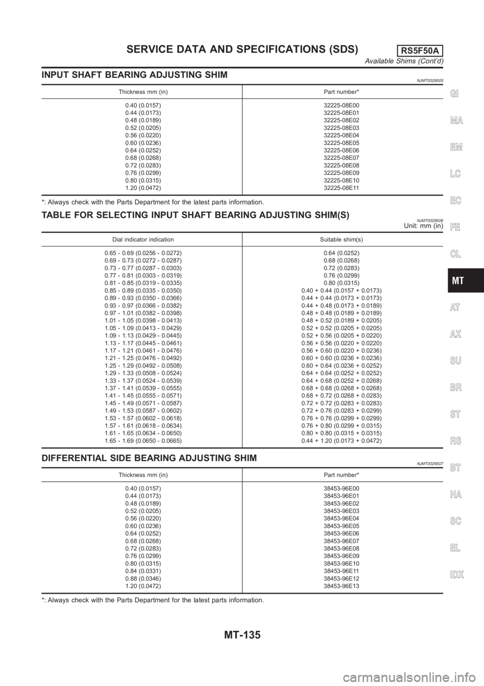
INPUT SHAFT BEARING ADJUSTING SHIMNJMT0029S05
Thickness mm (in) Part number*
0.40 (0.0157)
0.44 (0.0173)
0.48 (0.0189)
0.52 (0.0205)
0.56 (0.0220)
0.60 (0.0236)
0.64 (0.0252)
0.68 (0.0268)
0.72 (0.0283)
0.76 (0.0299)
0.80 (0.0315)
1.20 (0.0472)32225-08E00
32225-08E01
32225-08E02
32225-08E03
32225-08E04
32225-08E05
32225-08E06
32225-08E07
32225-08E08
32225-08E09
32225-08E10
32225-08E11
*: Always check with the Parts Department for the latest parts information.
TABLE FOR SELECTING INPUT SHAFT BEARING ADJUSTING SHIM(S)NJMT0029S06Unit: mm (in)
Dial indicator indication Suitable shim(s)
0.65 - 0.69 (0.0256 - 0.0272)
0.69 - 0.73 (0.0272 - 0.0287)
0.73 - 0.77 (0.0287 - 0.0303)
0.77 - 0.81 (0.0303 - 0.0319)
0.81 - 0.85 (0.0319 - 0.0335)
0.85 - 0.89 (0.0335 - 0.0350)
0.89 - 0.93 (0.0350 - 0.0366)
0.93 - 0.97 (0.0366 - 0.0382)
0.97 - 1.01 (0.0382 - 0.0398)
1.01 - 1.05 (0.0398 - 0.0413)
1.05 - 1.09 (0.0413 - 0.0429)
1.09 - 1.13 (0.0429 - 0.0445)
1.13 - 1.17 (0.0445 - 0.0461)
1.17 - 1.21 (0.0461 - 0.0476)
1.21 - 1.25 (0.0476 - 0.0492)
1.25 - 1.29 (0.0492 - 0.0508)
1.29 - 1.33 (0.0508 - 0.0524)
1.33 - 1.37 (0.0524 - 0.0539)
1.37 - 1.41 (0.0539 - 0.0555)
1.41 - 1.45 (0.0555 - 0.0571)
1.45 - 1.49 (0.0571 - 0.0587)
1.49 - 1.53 (0.0587 - 0.0602)
1.53 - 1.57 (0.0602 - 0.0618)
1.57 - 1.61 (0.0618 - 0.0634)
1.61 - 1.65 (0.0634 - 0.0650)
1.65 - 1.69 (0.0650 - 0.0665)0.64 (0.0252)
0.68 (0.0268)
0.72 (0.0283)
0.76 (0.0299)
0.80 (0.0315)
0.40 + 0.44 (0.0157 + 0.0173)
0.44 + 0.44 (0.0173 + 0.0173)
0.44 + 0.48 (0.0173 + 0.0189)
0.48 + 0.48 (0.0189 + 0.0189)
0.48 + 0.52 (0.0189 + 0.0205)
0.52 + 0.52 (0.0205 + 0.0205)
0.52 + 0.56 (0.0205 + 0.0220)
0.56 + 0.56 (0.0220 + 0.0220)
0.56 + 0.60 (0.0220 + 0.0236)
0.60 + 0.60 (0.0236 + 0.0236)
0.60 + 0.64 (0.0236 + 0.0252)
0.64 + 0.64 (0.0252 + 0.0252)
0.64 + 0.68 (0.0252 + 0.0268)
0.68 + 0.68 (0.0268 + 0.0268)
0.68 + 0.72 (0.0268 + 0.0283)
0.72 + 0.72 (0.0283 + 0.0283)
0.72 + 0.76 (0.0283 + 0.0299)
0.76 + 0.76 (0.0299 + 0.0299)
0.76 + 0.80 (0.0299 + 0.0315)
0.80 + 0.80 (0.0315 + 0.0315)
0.44 + 1.20 (0.0173 + 0.0472)
DIFFERENTIAL SIDE BEARING ADJUSTING SHIMNJMT0029S07
Thickness mm (in) Part number*
0.40 (0.0157)
0.44 (0.0173)
0.48 (0.0189)
0.52 (0.0205)
0.56 (0.0220)
0.60 (0.0236)
0.64 (0.0252)
0.68 (0.0268)
0.72 (0.0283)
0.76 (0.0299)
0.80 (0.0315)
0.84 (0.0331)
0.88 (0.0346)
1.20 (0.0472)38453-96E00
38453-96E01
38453-96E02
38453-96E03
38453-96E04
38453-96E05
38453-96E06
38453-96E07
38453-96E08
38453-96E09
38453-96E10
38453-96E11
38453-96E12
38453-96E13
*: Always check with the Parts Department for the latest parts information.
GI
MA
EM
LC
EC
FE
CL
AT
AX
SU
BR
ST
RS
BT
HA
SC
EL
IDX
SERVICE DATA AND SPECIFICATIONS (SDS)RS5F50A
Available Shims (Cont’d)
MT-135
Page 1456 of 3189
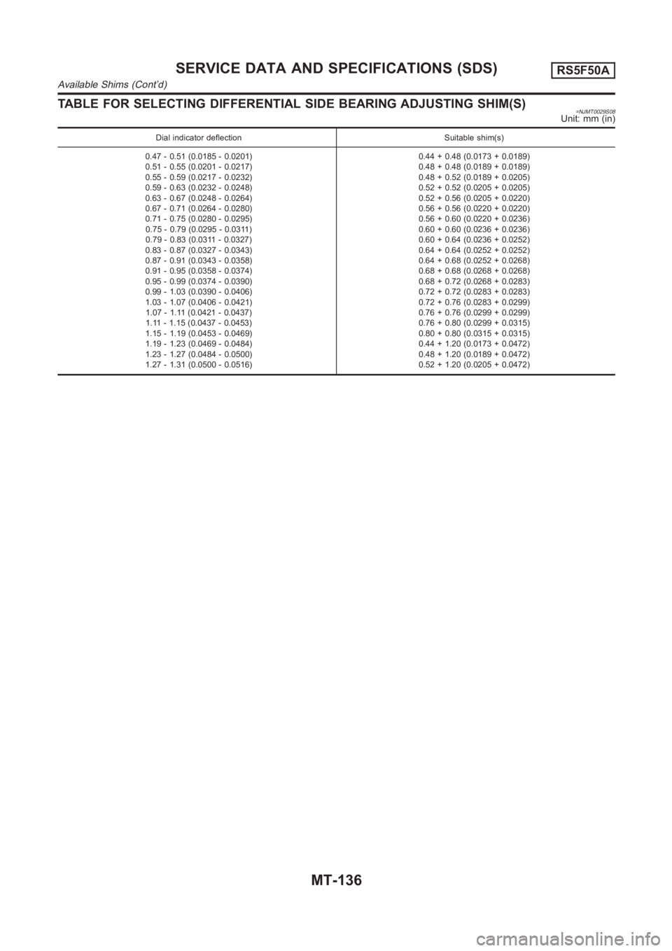
TABLE FOR SELECTING DIFFERENTIAL SIDE BEARING ADJUSTING SHIM(S)=NJMT0029S08Unit: mm (in)
Dial indicator deflection Suitable shim(s)
0.47 - 0.51 (0.0185 - 0.0201)
0.51 - 0.55 (0.0201 - 0.0217)
0.55 - 0.59 (0.0217 - 0.0232)
0.59 - 0.63 (0.0232 - 0.0248)
0.63 - 0.67 (0.0248 - 0.0264)
0.67 - 0.71 (0.0264 - 0.0280)
0.71 - 0.75 (0.0280 - 0.0295)
0.75 - 0.79 (0.0295 - 0.0311)
0.79 - 0.83 (0.0311 - 0.0327)
0.83 - 0.87 (0.0327 - 0.0343)
0.87 - 0.91 (0.0343 - 0.0358)
0.91 - 0.95 (0.0358 - 0.0374)
0.95 - 0.99 (0.0374 - 0.0390)
0.99 - 1.03 (0.0390 - 0.0406)
1.03 - 1.07 (0.0406 - 0.0421)
1.07 - 1.11 (0.0421 - 0.0437)
1.11 - 1.15 (0.0437 - 0.0453)
1.15 - 1.19 (0.0453 - 0.0469)
1.19 - 1.23 (0.0469 - 0.0484)
1.23 - 1.27 (0.0484 - 0.0500)
1.27 - 1.31 (0.0500 - 0.0516)0.44 + 0.48 (0.0173 + 0.0189)
0.48 + 0.48 (0.0189 + 0.0189)
0.48 + 0.52 (0.0189 + 0.0205)
0.52 + 0.52 (0.0205 + 0.0205)
0.52 + 0.56 (0.0205 + 0.0220)
0.56 + 0.56 (0.0220 + 0.0220)
0.56 + 0.60 (0.0220 + 0.0236)
0.60 + 0.60 (0.0236 + 0.0236)
0.60 + 0.64 (0.0236 + 0.0252)
0.64 + 0.64 (0.0252 + 0.0252)
0.64 + 0.68 (0.0252 + 0.0268)
0.68 + 0.68 (0.0268 + 0.0268)
0.68 + 0.72 (0.0268 + 0.0283)
0.72 + 0.72 (0.0283 + 0.0283)
0.72 + 0.76 (0.0283 + 0.0299)
0.76 + 0.76 (0.0299 + 0.0299)
0.76 + 0.80 (0.0299 + 0.0315)
0.80 + 0.80 (0.0315 + 0.0315)
0.44 + 1.20 (0.0173 + 0.0472)
0.48 + 1.20 (0.0189 + 0.0472)
0.52 + 1.20 (0.0205 + 0.0472)
SERVICE DATA AND SPECIFICATIONS (SDS)RS5F50A
Available Shims (Cont’d)
MT-136
Page 1459 of 3189
AT-3
D
E
F
G
H
I
J
K
L
MA
B
AT Line Pressure Test ............................................... 265
Road Test ............................................................. 266
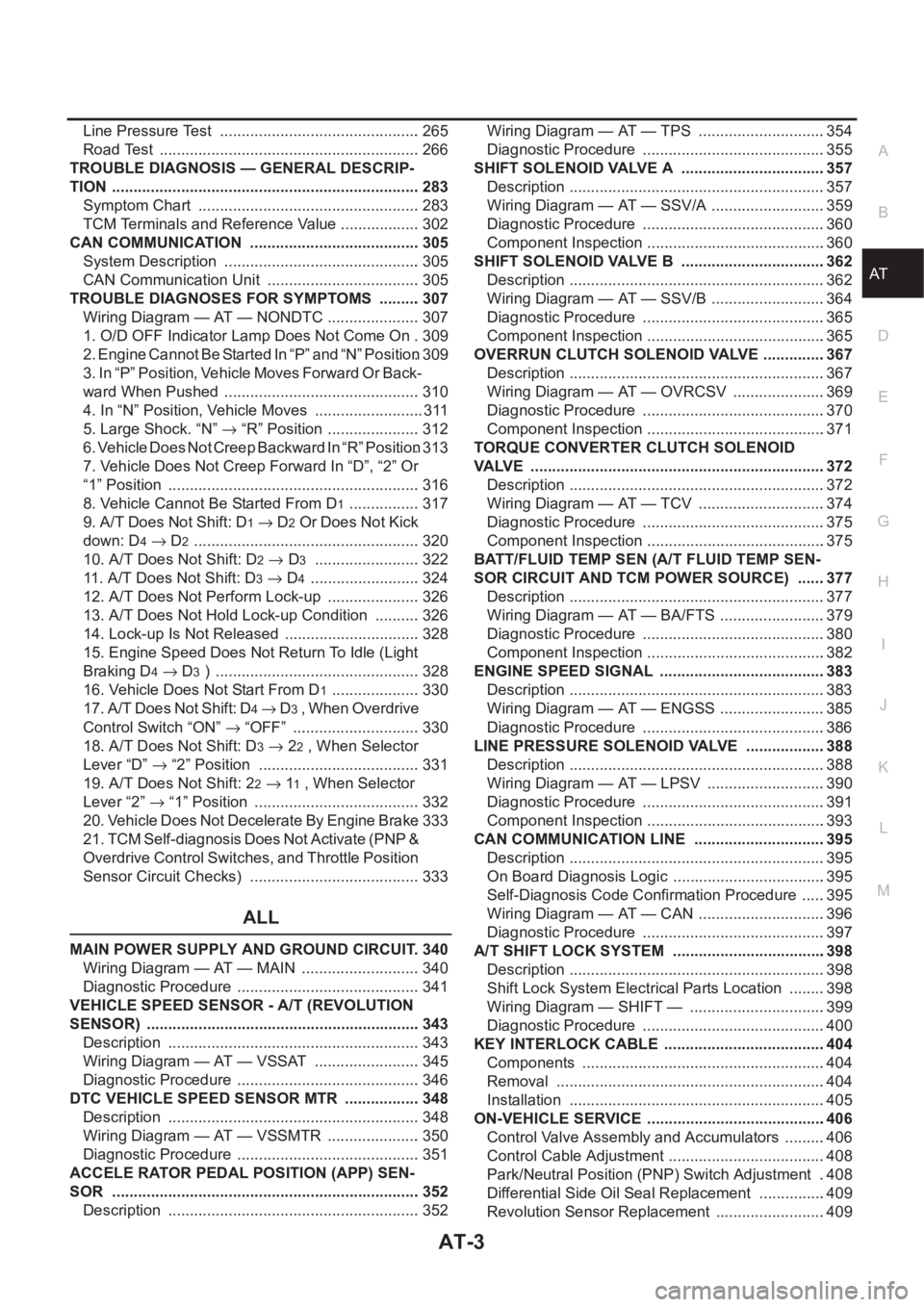
TROUBLE DIAGNOSIS — GENERAL DESCRIP-
TION ........................................................................ 283
Symptom Chart .................................................... 283
TCM Terminals and Reference Value ................... 302
CAN COMMUNICATION ........................................ 305
System Description .............................................. 305
CAN Communication Unit .................................... 305
TROUBLE DIAGNOSES FOR SYMPTOMS .......... 307
Wiring Diagram — AT — NONDTC ...................... 307
1. O/D OFF Indicator Lamp Does Not Come On . 309
2. Engine Cannot Be Started In “P” and “N” Position . 309
3. In “P” Position, Vehicle Moves Forward Or Back-
ward When Pushed .............................................. 310
4. In “N” Position, Vehicle Moves .......................... 311
5. Large Shock. “N” → “R” Position ...................... 312
6. Vehicle Does Not Creep Backward In “R” Position . 313
7. Vehicle Does Not Creep Forward In “D”, “2” Or
“1” Position ........................................................... 316
8. Vehicle Cannot Be Started From D
1 ................. 317
9. A/T Does Not Shift: D
1→ D2 Or Does Not Kick
down: D
4→ D2 ..................................................... 320
10. A/T Does Not Shift: D
2→ D3 ......................... 322
11. A/T Does Not Shift: D
3→ D4 .......................... 324
12. A/T Does Not Perform Lock-up ...................... 326
13. A/T Does Not Hold Lock-up Condition ........... 326
14. Lock-up Is Not Released ................................ 328
15. Engine Speed Does Not Return To Idle (Light
Braking D
4→ D3 ) ................................................ 328
16. Vehicle Does Not Start From D
1 ..................... 330
17. A/T Does Not Shift: D
4→ D3 , When Overdrive
Control Switch “ON” → “OFF” .............................. 330
18. A/T Does Not Shift: D
3→ 22 , When Selector
Lever “D” → “2” Position ...................................... 331
19. A/T Does Not Shift: 2
2→ 11 , When Selector
Lever “2” → “1” Position ....................................... 332
20. Vehicle Does Not Decelerate By Engine Brake . 333
21. TCM Self-diagnosis Does Not Activate (PNP &
Overdrive Control Switches, and Throttle Position
Sensor Circuit Checks) ........................................ 333
ALL
MAIN POWER SUPPLY AND GROUND CIRCUIT . 340
Wiring Diagram — AT — MAIN ............................ 340
Diagnostic Procedure ........................................... 341
VEHICLE SPEED SENSOR - A/T (REVOLUTION
SENSOR) ................................................................ 343
Description ........................................................... 343
Wiring Diagram — AT — VSSAT ......................... 345
Diagnostic Procedure ........................................... 346
DTC VEHICLE SPEED SENSOR MTR .................. 348
Description ........................................................... 348
Wiring Diagram — AT — VSSMTR ...................... 350
Diagnostic Procedure ........................................... 351
ACCELE RATOR PEDAL POSITION (APP) SEN-
SOR ........................................................................ 352
Description ........................................................... 352Wiring Diagram — AT — TPS ..............................354
Diagnostic Procedure ...........................................355
SHIFT SOLENOID VALVE A ..................................357
Description ............................................................357
Wiring Diagram — AT — SSV/A ...........................359
Diagnostic Procedure ...........................................360
Component Inspection ..........................................360
SHIFT SOLENOID VALVE B ..................................362
Description ............................................................362
Wiring Diagram — AT — SSV/B ...........................364
Diagnostic Procedure ...........................................365
Component Inspection ..........................................365
OVERRUN CLUTCH SOLENOID VALVE ...............367
Description ............................................................367
Wiring Diagram — AT — OVRCSV ......................369
Diagnostic Procedure ...........................................370
Component Inspection ..........................................371
TORQUE CONVERTER CLUTCH SOLENOID
VALVE .....................................................................372
Description ............................................................372
Wiring Diagram — AT — TCV ..............................374
Diagnostic Procedure ...........................................375
Component Inspection ..........................................375
BATT/FLUID TEMP SEN (A/T FLUID TEMP SEN-
SOR CIRCUIT AND TCM POWER SOURCE) .......377
Description ............................................................377
Wiring Diagram — AT — BA/FTS .........................379
Diagnostic Procedure ...........................................380
Component Inspection ..........................................382
ENGINE SPEED SIGNAL .......................................383
Description ............................................................383
Wiring Diagram — AT — ENGSS .........................385
Diagnostic Procedure ...........................................386
LINE PRESSURE SOLENOID VALVE ...................388
Description ............................................................388
Wiring Diagram — AT — LPSV ............................390
Diagnostic Procedure ...........................................391
Component Inspection ..........................................393
CAN COMMUNICATION LINE ...............................395
Description ............................................................395
On Board Diagnosis Logic ....................................395
Self-Diagnosis Code Confirmation Procedure ......395
Wiring Diagram — AT — CAN ..............................396
Diagnostic Procedure ...........................................397
A/T SHIFT LOCK SYSTEM ....................................398
Description ............................................................398
Shift Lock System Electrical Parts Location .........398
Wiring Diagram — SHIFT — ................................399
Diagnostic Procedure ...........................................400
KEY INTERLOCK CABLE ......................................404
Components .........................................................404
Removal ...............................................................404
Installation ............................................................405
ON-VEHICLE SERVICE ..........................................406
Control Valve Assembly and Accumulators ..........406
Control Cable Adjustment .....................................408
Park/Neutral Position (PNP) Switch Adjustment ..408
Differential Side Oil Seal Replacement ................409
Revolution Sensor Replacement ..........................409
Page 1465 of 3189
PREPARATION
AT-9
D
E
F
G
H
I
J
K
L
MA
B
AT
PREPARATIONPFP:00100
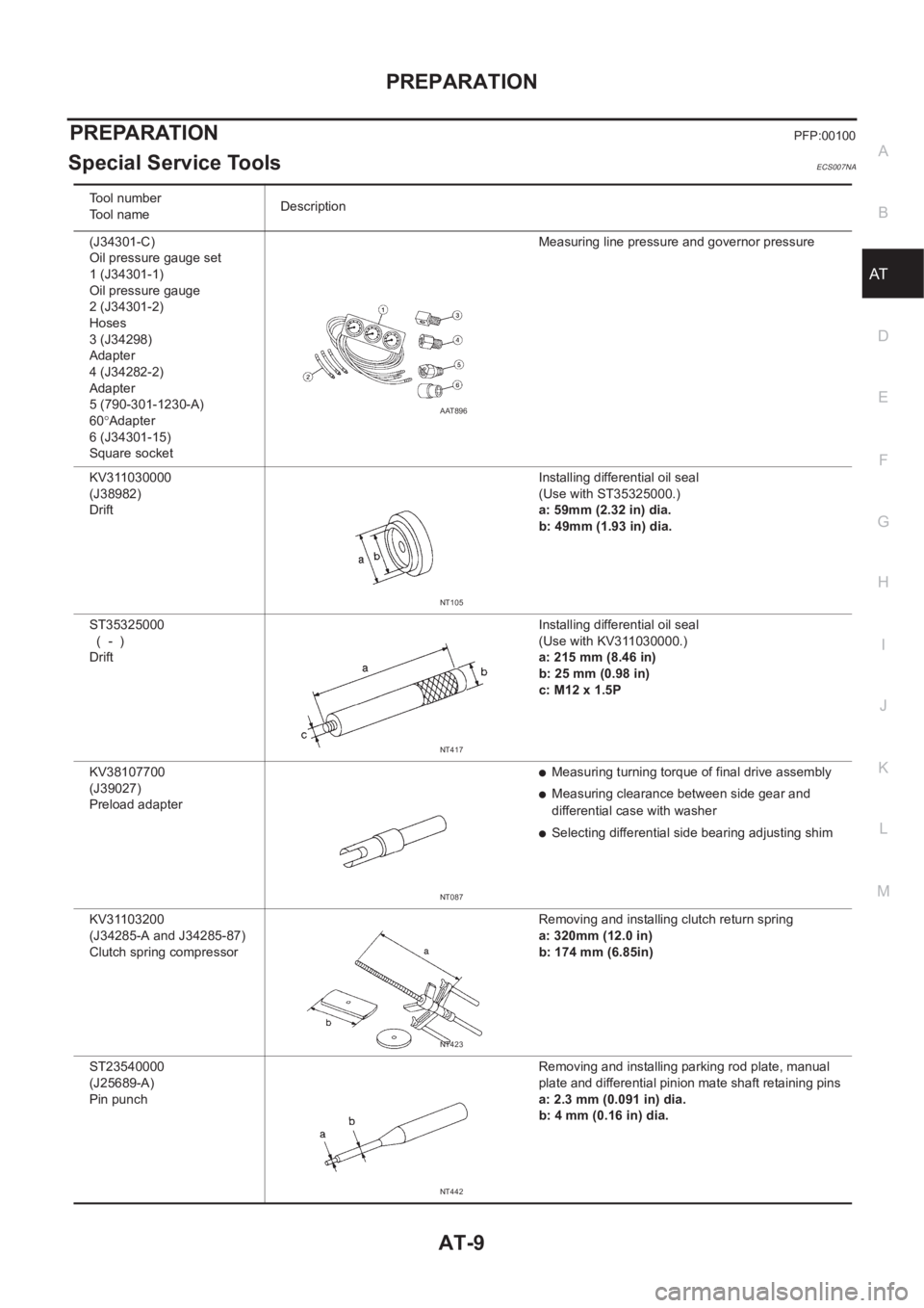
Special Service ToolsECS007NA
Tool number
Tool nameDescription
(J34301-C)
Oil pressure gauge set
1 (J34301-1)
Oil pressure gauge
2 (J34301-2)
Hoses
3 (J34298)
Adapter
4 (J34282-2)
Adapter
5 (790-301-1230-A)
60°Adapter
6 (J34301-15)
Square socketMeasuring line pressure and governor pressure
KV311030000
(J38982)
Drift Installing differential oil seal
(Use with ST35325000.)
a: 59mm (2.32 in) dia.
b: 49mm (1.93 in) dia.
ST35325000
( - )
Drift Installing differential oil seal
(Use with KV311030000.)
a: 215 mm (8.46 in)
b: 25 mm (0.98 in)
c: M12 x 1.5P
KV38107700
(J39027)
Preload adapter
●Measuring turning torque of final drive assembly
●Measuring clearance between side gear and
differential case with washer
●Selecting differential side bearing adjusting shim
KV31103200
(J34285-A and J34285-87)
Clutch spring compressor Removing and installing clutch return spring
a: 320mm (12.0 in)
b: 174 mm (6.85in)
ST23540000
(J25689-A)
Pin punch Removing and installing parking rod plate, manual
plate and differential pinion mate shaft retaining pins
a: 2.3 mm (0.091 in) dia.
b: 4 mm (0.16 in) dia.
AAT896
NT105
NT417
NT087
NT423
NT442