Page 1340 of 3189
SMT563AA
Replacing Oil SealNJMT0035DIFFERENTIAL OIL SEALNJMT0035S011. Drain gear oil from transaxle.
2. Remove drive shafts. Refer to AX-11, “Removal”.
3. Remove differential oil seal.
SMT564AB
SMT925DA
4. Install differential oil seal.
Apply multi-purpose grease to seal lip of oil seal before
installing.
5. Install drive shafts. Refer to AX-12, “Installation”.
SMT926DA
SMT927D
Install differential oil seal so that dimension “A” and “B”
are within specifications.
Unit: mm (in)
Item Model A B
DimensionRS5F30A
−0.5 (−0.020) to 0.5 (0.020) RS5F70A
RS5F50A
ON-VEHICLE SERVICE
Replacing Oil Seal
MT-20
Page 1350 of 3189
NJMT0039
Case ComponentsNJMT0039S01
SMT956DA
1. Clutch housing
2. Input shaft oil seal
3. Oil pocket
4. Bearing retainer
5. Torx screw
6. Filler plug
7. Air breather tube
8. Welch plug
9. O-ring10. Case cover
11. Back-up lamp switch
12. Differential oil seal
13. Drain plug
14. Transmission case
15. Oil gutter
16. Reverse idler shaft
17. Oil channel
18. Striking rod oil seal19. Boot
20. Differential oil seal
21. O-ring
22. Speedometer pinion assembly
23. Magnet
24. Earth term
25. Welch plug
26. Welch plug
27. PNP switch
OVERHAULRS5F30A
Case Components
MT-30
Page 1351 of 3189

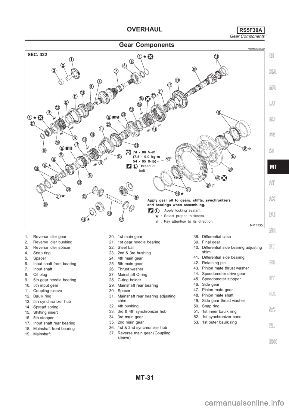
Gear Components=NJMT0039S02
NMT135
1. Reverse idler gear
2. Reverse idler bushing
3. Reverse idler spacer
4. Snap ring
5. Spacer
6. Input shaft front bearing
7. Input shaft
8. Oil plug
9. 5th gear needle bearing
10. 5th input gear
11. Coupling sleeve
12. Baulk ring
13. 5th synchronizer hub
14. Spread spring
15. Shifting insert
16. 5th stopper
17. Input shaft rear bearing
18. Mainshaft front bearing
19. Mainshaft20. 1st main gear
21. 1st gear needle bearing
22. Steel ball
23. 2nd & 3rd bushing
24. 4th main gear
25. 5th main gear
26. Thrust washer
27. Mainshaft C-ring
28. C-ring holder
29. Mainshaft rear bearing
30. Spacer
31. Mainshaft rear bearing adjusting
shim
32. 4th bushing
33. 3rd & 4th synchronizer hub
34. 3rd main gear
35. 2nd main gear
36. 1st & 2nd synchronizer hub
37. Reverse main gear (Coupling
sleeve)38. Differential case
39. Final gear
40. Differential side bearing adjusting
shim
41. Differential side bearing
42. Retaining pin
43. Pinion mate thrust washer
44. Speedometer drive gear
45. Speedometer stopper
46. Side gear
47. Pinion mate gear
48. Pinion mate shaft
49. Side gear thrust washer
50. Snap ring
51. 1st inner baulk ring
52. 1st synchronizer cone
53. 1st outer baulk ring
GI
MA
EM
LC
EC
FE
CL
AT
AX
SU
BR
ST
RS
BT
HA
SC
EL
IDX
OVERHAULRS5F30A
Gear Components
MT-31
Page 1363 of 3189
SMT606AA
6. Press on 5th main gear.
SMT592-A
7. Install thrust washer.
8. Select and install mainshaft C-ring that gives proper clearance
of groove in mainshaft.
Allowable clearance of groove:
0-0.1mm(0-0.004in)
Mainshaft C-ring:
Refer to SDS, MT-120.
9. Install C-ring holder.
SMT607AA
10. Press on mainshaft rear bearing.
SMT639
11. Press on mainshaft front bearing.
12. Measure gear end play as the final check — Refer to
“DISASSEMBLY”, MT-39.
SMT647-A
Final Drive
DISASSEMBLYNJMT00481. Remove final gear.
2. Remove speedometer drive gear by cutting it.
3. Press out differential side bearings.
Be careful not to mix up the right and left bearings.
GI
MA
EM
LC
EC
FE
CL
AT
AX
SU
BR
ST
RS
BT
HA
SC
EL
IDX
REPAIR FOR COMPONENT PARTSRS5F30A
Mainshaft and Gears (Cont’d)
MT-43
Page 1364 of 3189
SMT147AA
4. Drive out retaining pin and draw out pinion mate shaft.
5. Remove pinion mate gears and side gears.
SMT083A
INSPECTIONNJMT0049Gear, Washer, Shaft and CaseNJMT0049S01Check mating surfaces of differential case, side gears and
pinion mate gears.
Check washers for wear.
SPD715
BearingsNJMT0049S03Make sure bearings roll freely and are free from noise, cracks,
pitting or wear.
When replacing tapered roller bearing, replace outer and
inner race as a set.
SMT839
ASSEMBLYNJMT00501. Attach side gear thrust washers to side gears and install in
differential case.
2. Install pinion mate thrust washers and pinion mate gears.
SMT087A
3. Insert pinion mate shaft.
When inserting, be careful not to damage pinion mate
thrust washers.
REPAIR FOR COMPONENT PARTSRS5F30A
Final Drive (Cont’d)
MT-44
Page 1365 of 3189
SMT610AB
4. Measure clearance between side gear and differential case
with washers following the procedure below:
a. Set Tool and dial indicator on side gear.
SMT611A
b. Move side gear up and down to measure dial indicator deflec-
tion. Always measure indicator deflection on both side gears.
Clearance between side gear and differential case with
washers:
0.1 - 0.2 mm (0.004 - 0.008 in)
c. If not within specification, adjust clearance by changing thick-
ness of side gear thrust washers.
Differential side gear thrust washer:
Refer to SDS, MT-120.
SMT147AA
5. Install retaining pin.
Make sure that retaining pin is flush with case.
SMT609A
6. Install final gear.
Apply locking sealant to final gear fixing bolts before
installing them.
7. Install speedometer drive gear and stopper.
SMT648
8. Press on differential side bearings.
GI
MA
EM
LC
EC
FE
CL
AT
AX
SU
BR
ST
RS
BT
HA
SC
EL
IDX
REPAIR FOR COMPONENT PARTSRS5F30A
Final Drive (Cont’d)
MT-45
Page 1368 of 3189
Mainshaft Rear Bearing Outer RaceNJMT0052S04Refer to “Mainshaft Bearing Preload”, MT-121.
Differential Side Bearing Outer RaceNJMT0052S06Refer to “Differential Side Bearing Preload”, MT-121.
REPAIR FOR COMPONENT PARTSRS5F30A
Case Components (Cont’d)
MT-48
Page 1369 of 3189

NJMT0091
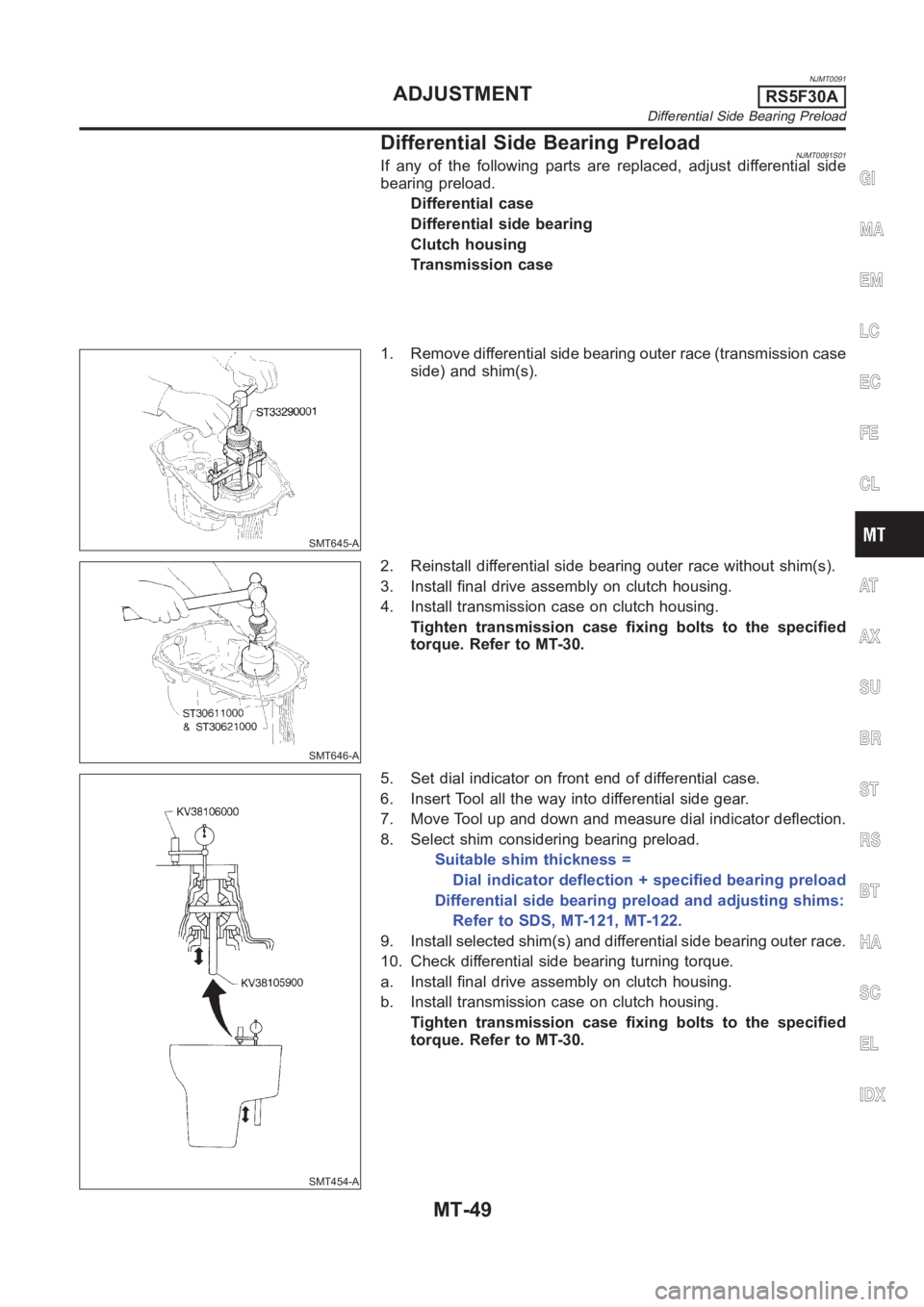
Differential Side Bearing PreloadNJMT0091S01If any of the following parts are replaced, adjust differential side
bearing preload.
Differential case
Differential side bearing
Clutch housing
Transmission case
SMT645-A
1. Remove differential side bearing outer race (transmission case
side) and shim(s).
SMT646-A
2. Reinstall differential side bearing outer race without shim(s).
3. Install final drive assembly on clutch housing.
4. Install transmission case on clutch housing.
Tighten transmission case fixing bolts to the specified
torque. Refer to MT-30.
SMT454-A
5. Set dial indicator on front end of differential case.
6. Insert Tool all the way into differential side gear.
7. Move Tool up and down and measure dial indicator deflection.
8. Select shim considering bearing preload.
Suitable shim thickness =
Dial indicator deflection + specified bearing preload
Differential side bearing preload and adjusting shims:
Refer to SDS, MT-121, MT-122.
9. Install selected shim(s) and differential side bearing outer race.
10. Check differential side bearing turning torque.
a. Install final drive assembly on clutch housing.
b. Install transmission case on clutch housing.
Tighten transmission case fixing bolts to the specified
torque. Refer to MT-30.
GI
MA
EM
LC
EC
FE
CL
AT
AX
SU
BR
ST
RS
BT
HA
SC
EL
IDX
ADJUSTMENTRS5F30A
Differential Side Bearing Preload
MT-49