Page 1370 of 3189

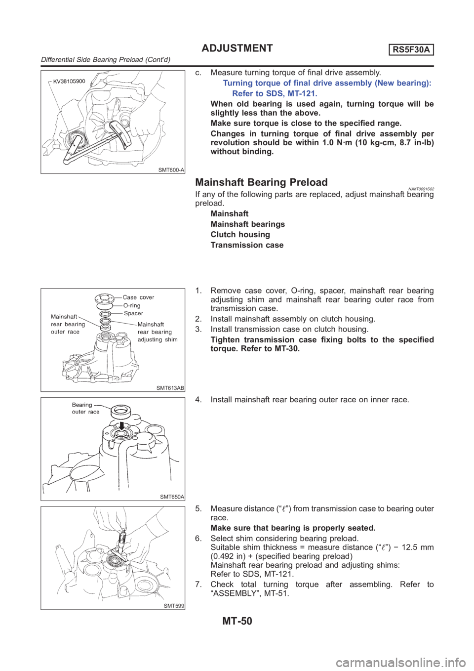
SMT600-A
c. Measure turning torque of final drive assembly.
Turning torque of final drive assembly (New bearing):
Refer to SDS, MT-121.
When old bearing is used again, turning torque will be
slightly less than the above.
Make sure torque is close to the specified range.
Changes in turning torque of final drive assembly per
revolution should be within 1.0 N·m (10 kg-cm, 8.7 in-lb)
without binding.
Mainshaft Bearing PreloadNJMT0091S02If any of the following parts are replaced, adjust mainshaft bearing
preload.
Mainshaft
Mainshaft bearings
Clutch housing
Transmission case
SMT613AB
1. Remove case cover, O-ring, spacer, mainshaft rear bearing
adjusting shim and mainshaft rear bearing outer race from
transmission case.
2. Install mainshaft assembly on clutch housing.
3. Install transmission case on clutch housing.
Tighten transmission case fixing bolts to the specified
torque. Refer to MT-30.
SMT650A
4. Install mainshaft rear bearing outer race on inner race.
SMT599
5. Measure distance (“�”) from transmission case to bearing outer
race.
Make sure that bearing is properly seated.
6. Select shim considering bearing preload.
Suitable shim thickness = measure distance (“�”) − 12.5 mm
(0.492 in) + (specified bearing preload)
Mainshaft rear bearing preload and adjusting shims:
Refer to SDS, MT-121.
7. Check total turning torque after assembling. Refer to
“ASSEMBLY”, MT-51.
ADJUSTMENTRS5F30A
Differential Side Bearing Preload (Cont’d)
MT-50
Page 1374 of 3189
NJMT0054
Case ComponentsNJMT0054S02
SMT942D
1. Clutch housing
2. Dust seal
3. Oil pocket
4. Check plug
5. Input shaft oil seal
6. Oil channel
7. Mainshaft front bearing
8. Bearing retainer
9. Bush
10. Reverse idler gear front thrust
washer
11. Reverse idler gear
12. Reverse idler gear bearing
13. Reverse idler gear rear thrust
washer14. O-ring
15. Reverse idler gear shaft
16. Snap ring
17. Reverse switch
18. Filler plug
19. Side cover gasket
20. Side cover
21. Welch plug
22. Mainshaft bearing snap ring
23. Mainshaft rear bearing adjusting
shim
24. O-ring
25. Rear cover26. Differential oil seal
27. Drain plug
28. PNP switch
29. Transmission case
30. Oil gutter
31. Welch plug
32. Magnet
33. Boot
34. Striking rod oil seal
35. Welch plug
36. Differential oil seal
37. O-ring
38. Speedometer pinion
OVERHAULRS5F70A
Case Components
MT-54
Page 1377 of 3189
Final Drive Components=NJMT0054S05
YMT001
1. Differential side bearing adjusting
shim
2. Differential side bearing outer race
3. Differential side bearing
4. Final gear
5. Differential case6. Speedometer drive gear
7. Speedometer stopper
8. Differential side bearing
9. Differential side bearing outer race
10. Pinion mate thrust washer11. Pinion mate gear
12. Side gear thrust washer
13. Side gear
14. Pinion mate shaft
15. Lock pin
GI
MA
EM
LC
EC
FE
CL
AT
AX
SU
BR
ST
RS
BT
HA
SC
EL
IDX
OVERHAULRS5F70A
Final Drive Components
MT-57
Page 1379 of 3189
SMT649D
9. Remove mounting bolts.
10. Remove input shaft rear bearing adjusting shim from transaxle
case.
SMT650D
11. Remove oil gutter from case.
SMT651DB
12. Remove differential side bearing outer race and adjusting shim
from case.
SMT653DB
13. Remove differential oil seal from case.
SMT839DB
14. Remove welch plugs from case.
GI
MA
EM
LC
EC
FE
CL
AT
AX
SU
BR
ST
RS
BT
HA
SC
EL
IDX
DISASSEMBLYRS5F70A
Transaxle Case (Cont’d)
MT-59
Page 1383 of 3189
SMT669DB
30. Remove differential oil seal from housing.
SMT670DB
31. Remove differential side outer race from housing.
GI
MA
EM
LC
EC
FE
CL
AT
AX
SU
BR
ST
RS
BT
HA
SC
EL
IDX
DISASSEMBLYRS5F70A
Clutch Housing (Cont’d)
MT-63
Page 1397 of 3189
SMT720DB
24. Install mainshaft rear bearing.
SMT721D
25. Install mainshaft C-ring.
26. Using feeler gauge, measure the end play of mainshaft rear
bearing, and check if it satisfies the following specification.
End play:
0 - 0.06 mm (0 - 0.0024 in)
Mainshaft C-rings:
Refer to SDS, MT-126.
SMT678D
27. Install C-ring holder.
SMT677D
28. Install snap ring.
29. Measure gear end play as a final check. Refer to, MT-69.
SMT610AH
Final Drive
PRE-INSPECTIONNJMT0062Check the clearance between side gear and differential case
as follows.
1. Clean final drive assembly sufficiently to prevent side gear
thrust washer, differential case, side gear, and other parts from
sticking by gear oil.
GI
MA
EM
LC
EC
FE
CL
AT
AX
SU
BR
ST
RS
BT
HA
SC
EL
IDX
REPAIR FOR COMPONENT PARTSRS5F70A
Mainshaft and Gears (Cont’d)
MT-77
Page 1398 of 3189

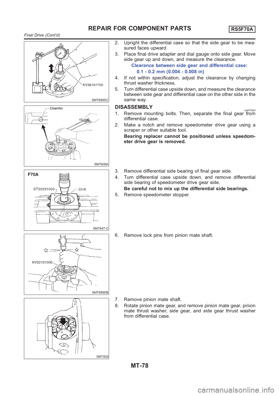
SMT685DC
2. Upright the differential case so that the side gear to be mea-
sured faces upward.
3. Place final drive adapter and dial gauge onto side gear. Move
side gear up and down, and measure the clearance.
Clearance between side gear and differential case:
0.1 - 0.2 mm (0.004 - 0.008 in)
4. If not within specification, adjust the clearance by changing
thrust washer thickness.
5. Turn differential case upside down, and measure the clearance
between side gear and differential case on the other side in the
same way.
SMT609A
DISASSEMBLYNJMT00631. Remove mounting bolts. Then, separate the final gear from
differential case.
2. Make a notch and remove speedometer drive gear using a
scraper or other suitable tool.
Bearing replacer cannot be positioned unless speedom-
eter drive gear is removed.
SMT647-C
3. Remove differential side bearing of final gear side.
4. Turn differential case upside down, and remove differential
side bearing of speedometer drive gear side.
Be careful not to mix up the differential side bearings.
5. Remove speedometer stopper.
SMT689DB
6. Remove lock pins from pinion mate shaft.
SMT839
7. Remove pinion mate shaft.
8. Rotate pinion mate gear, and remove pinion mate gear, pinion
mate thrust washer, side gear, and side gear thrust washer
from differential case.
REPAIR FOR COMPONENT PARTSRS5F70A
Final Drive (Cont’d)
MT-78
Page 1399 of 3189

SMT083A
INSPECTIONNJMT0064Gear, Washer, Shaft and CaseNJMT0064S01Check mating surfaces of differential case, side gears and
pinion mate gears.
Check washers for wear.
SPD715
BearingNJMT0064S03Make sure bearings roll freely and are free from noise, cracks,
pitting or wear.
When replacing tapered roller bearing, replace outer and
inner race as a set.
SMT062A
ASSEMBLYNJMT00651. Apply gear oil to sliding area of differential case, each gear,
and thrust washer.
2. Install side gear thrust washer and side gear into differential
case.
3. Position pinion mate gear and pinion mate thrust washer
diagonally, and install them into differential case while rotating.
SMT087A
4. Insert pinion mate shaft into differential case.
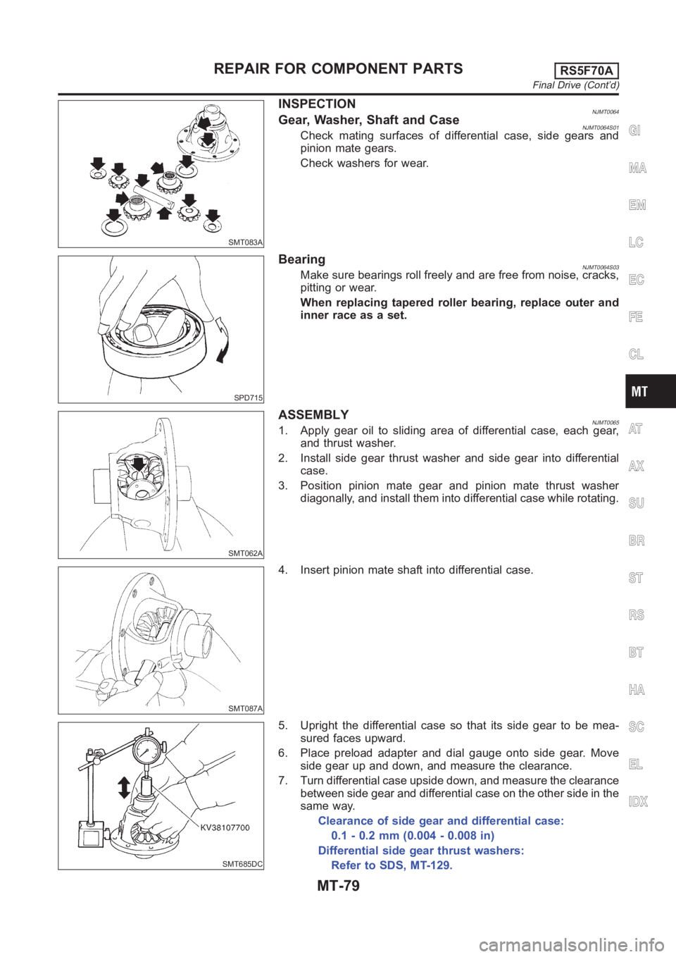
SMT685DC
5. Upright the differential case so that its side gear to be mea-
sured faces upward.
6. Place preload adapter and dial gauge onto side gear. Move
side gear up and down, and measure the clearance.
7. Turn differential case upside down, and measure the clearance
between side gear and differential case on the other side in the
same way.
Clearance of side gear and differential case:
0.1 - 0.2 mm (0.004 - 0.008 in)
Differential side gear thrust washers:
Refer to SDS, MT-129.
GI
MA
EM
LC
EC
FE
CL
AT
AX
SU
BR
ST
RS
BT
HA
SC
EL
IDX
REPAIR FOR COMPONENT PARTSRS5F70A
Final Drive (Cont’d)
MT-79