2003 NISSAN ALMERA N16 differential
[x] Cancel search: differentialPage 1976 of 3189
![NISSAN ALMERA N16 2003 Electronic Repair Manual AT-520
[ALL]
SERVICE DATA AND SPECIFICATIONS (SDS)
TABLE FOR SELECTING DIFFERENTIAL SIDE BEARING ADJUSTING SHIMS (FOR RE4F03B)
Unit: mm (in)
Reduction Pinion GearECS007U3
BEARING PRELOAD
TURNING TORQU NISSAN ALMERA N16 2003 Electronic Repair Manual AT-520
[ALL]
SERVICE DATA AND SPECIFICATIONS (SDS)
TABLE FOR SELECTING DIFFERENTIAL SIDE BEARING ADJUSTING SHIMS (FOR RE4F03B)
Unit: mm (in)
Reduction Pinion GearECS007U3
BEARING PRELOAD
TURNING TORQU](/manual-img/5/57350/w960_57350-1975.png)
AT-520
[ALL]
SERVICE DATA AND SPECIFICATIONS (SDS)
TABLE FOR SELECTING DIFFERENTIAL SIDE BEARING ADJUSTING SHIMS (FOR RE4F03B)
Unit: mm (in)
Reduction Pinion GearECS007U3
BEARING PRELOAD
TURNING TORQUE
Dial indicator deflection Suitable shim(s)
0.31 - 0.35 (0.0122 - 0.0138)
0.35 - 0.39 (0.0138 - 0.0154)
0.39 - 0.43 (0.0154 - 0.0169)
0.43 - 0.47 (0.0169 - 0.0185)
0.47 - 0.51 (0.0185 - 0.0201)
0.51 - 0.55 (0.0201 - 0.0217)
0.55 - 0.59 (0.0217 - 0.0232)
0.59 - 0.63 (0.0232 - 0.0248)
0.63 - 0.67 (0.0248 - 0.0264)
0.67 - 0.71 (0.0264 - 0.0280)
0.71 - 0.75 (0.0280 - 0.0295)
0.75 - 0.79 (0.0295 - 0.0311)
0.79 - 0.83 (0.0311 - 0.0327)
0.83 - 0.87 (0.0327 - 0.0343)
0.87 - 0.91 (0.0343 - 0.0358)
0.91 - 0.95 (0.0358 - 0.0374)
0.95 - 0.99 (0.0374 - 0.0390)
0.99 - 1.03 (0.0390 - 0.0406)
1.03 - 1.07 (0.0406 - 0.0421)
1.07 - 1.11 (0.0421 - 0.0437)
1.11 - 1.15 (0.0437 - 0.0453)
1.15 - 1.19 (0.0453 - 0.0469)
1.19 - 1.23 (0.0469 - 0.0484)
1.23 - 1.27 (0.0484 - 0.0500)
1.27 - 1.31 (0.0500 - 0.0516)
1.31 - 1.35 (0.0516 - 0.0531)
1.35 - 1.39 (0.0531 - 0.0547)
1.39 - 1.43 (0.0547 - 0.0563)
1.43 - 1.47 (0.0563 - 0.0579)
1.47 - 1.51 (0.0579 - 0.0594)
1.51 - 1.55 (0.0594 - 0.0610)
1.55 - 1.59 (0.0610 - 0.0626)
1.59 - 1.63 (0.0626 - 0.0642)
1.63 - 1.67 (0.0642 - 0.0657)
1.67 - 1.71 (0.0657 - 0.0673)
1.71 - 1.75 (0.0673 - 0.0689)
1.75 - 1.79 (0.0689 - 0.0705)
1.79 - 1.83 (0.0705 - 0.0720)
1.83 - 1.87 (0.0720 - 0.0736)
1.87 - 1.91 (0.0736 - 0.0752)
1.91 - 1.95 (0.0752 - 0.0768)0.40 (0.0157)
0.44 (0.0173)
0.48 (0.0189)
0.52 (0.0205)
0.56 (0.0220)
0.60 (0.0236)
0.64 (0.0252)
0.68 (0.0268)
0.72 (0.0283)
0.76 (0.0299)
0.80 (0.0315)
0.84 (0.0331)
0.88 (0.0346)
0.92 (0.0362)
0.48 (0.0189) + 0.48 (0.0189)
0.48 (0.0189) + 0.52 (0.0205)
0.52 (0.0205) + 0.52 (0.0205)
0.52 (0.0205) + 0.56 (0.0220)
0.56 (0.0220) + 0.56 (0.0220)
0.56 (0.0220) + 0.60 (0.0236)
0.60 (0.0236) + 0.60 (0.0236)
0.60 (0.0236) + 0.64 (0.0252)
0.64 (0.0252) + 0.64 (0.0252)
0.64 (0.0252) + 0.68 (0.0268)
0.68 (0.0268) + 0.68 (0.0268)
0.68 (0.0268) + 0.72 (0.0283)
1.44 (0.0567)
0.72 (0.0283) + 0.76 (0.0299)
0.76 (0.0299) + 0.76 (0.0299)
0.76 (0.0299) + 0.80 (0.0315)
0.80 (0.0315) + 0.80 (0.0315)
0.80 (0.0315) + 0.84 (0.0331)
0.84 (0.0331) + 0.84 (0.0331)
0.84 (0.0331) + 0.88 (0.0346)
0.88 (0.0346) + 0.88 (0.0346)
0.88 (0.0346) + 0.92 (0.0362)
0.92 (0.0362) + 0.92 (0.0362)
0.92 (0.0362) + 0.96 (0.0378)
0.96 (0.0378) + 0.96 (0.0378)
0.52 (0.0205) + 1.44 (0.0567)
0.56 (0.0220) + 1.44 (0.0567)
Reduction pinion gear bearing preload 0.05 mm (0.0020 in)
Turning torque of reduction pinion gear 0.1 - 0.69 N-m (1.1 - 7.0 kg-cm, 0.95 - 6.08 in-lb)
Page 2132 of 3189

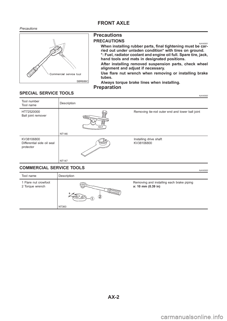
SBR686C
Precautions
PRECAUTIONSNJAX0001When installing rubber parts, final tightening must be car-
ried out under unladen condition* with tires on ground.
*: Fuel, radiator coolant and engine oil full. Spare tire, jack,
hand tools and mats in designated positions.
After installing removed suspension parts, check wheel
alignment and adjust if necessary.
Use flare nut wrench when removing or installing brake
tubes.
Always torque brake lines when installing.
Preparation
SPECIAL SERVICE TOOLSNJAX0002
Tool number
Tool nameDescription
HT72520000
Ball joint remover
NT146
Removing tie-rod outer end and lower ball joint
KV38106800
Differential side oil seal
protector
NT147
Installing drive shaft
KV38106800
COMMERCIAL SERVICE TOOLSNJAX0003
Tool name Description
1 Flare nut crowfoot
2 Torque wrench
NT360
Removing and installing each brake piping
a: 10 mm (0.39 in)
FRONT AXLE
Precautions
AX-2
Page 2142 of 3189

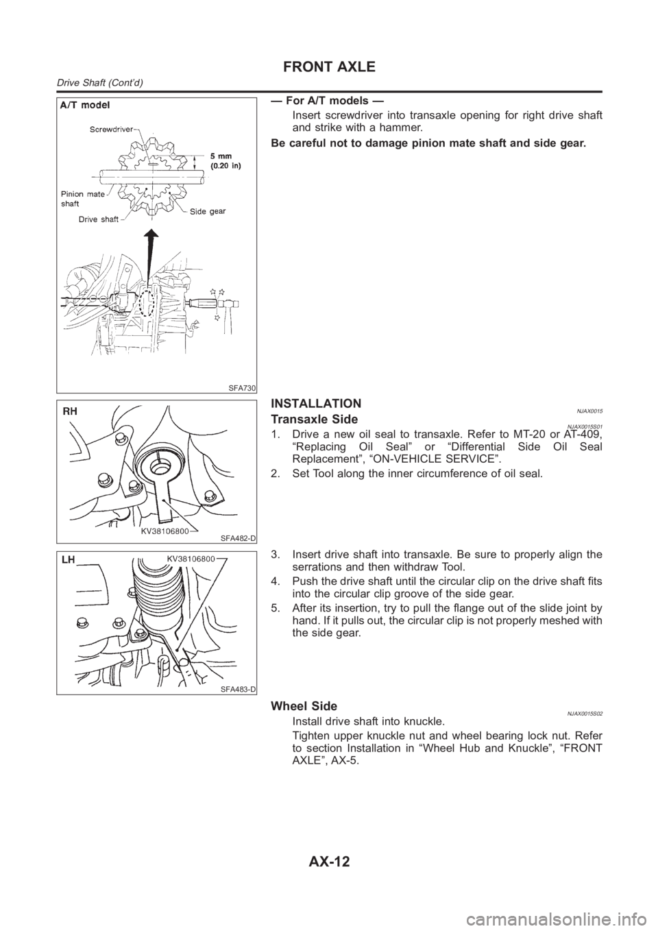
SFA730
— For A/T models —
Insert screwdriver into transaxle opening for right drive shaft
and strike with a hammer.
Be careful not to damage pinion mate shaft and side gear.
SFA482-D
INSTALLATIONNJAX0015Transaxle SideNJAX0015S011. Drive a new oil seal to transaxle. Refer to MT-20 or AT-409,
“Replacing Oil Seal” or “Differential Side Oil Seal
Replacement”, “ON-VEHICLE SERVICE”.
2. Set Tool along the inner circumference of oil seal.
SFA483-D
3. Insert drive shaft into transaxle. Be sure to properly align the
serrations and then withdraw Tool.
4. Push the drive shaft until the circular clip on the drive shaft fits
into the circular clip groove of the side gear.
5. After its insertion, try to pull the flange out of the slide joint by
hand. If it pulls out, the circular clip is not properly meshed with
the side gear.
Wheel SideNJAX0015S02Install drive shaft into knuckle.
Tighten upper knuckle nut and wheel bearing lock nut. Refer
to section Installation in “Wheel Hub and Knuckle”, “FRONT
AXLE”, AX-5.
FRONT AXLE
Drive Shaft (Cont’d)
AX-12
Page 3178 of 3189

COOL/F - Wiring diagram
(QG engine)................................EC-328, EC-601
COOL/F - Wiring diagram (YD engine) ........EC-130
Coolant mixture ratio......................................MA-21
Cooling circuit (engine).............................LC-12, 36
Cooling fan control (YD engine)...................EC-130
Cooling fan control system .......................LC-17, 42
Cooling fan motor (QG engine) .....EC-335, EC-608
Coupling sleeve (M/T)........................MT-31, 55, 93
Crankcase emission control system -
See positive crankcase ventilation
(YD engine).................................................EC-19
Crankcase ventilation system - See
Positive crankcase ventilation
(QG engine)................................EC-403, EC-722
Crankcase ventilation system - See
Positive crankcase ventilation
(YD engine).................................................EC-19
Crankshaft (QG engine).................................EM-71
Crankshaft (YD engine) .................................EM-75
Crankshaft position sensor (POS)
(QG engine)................................EC-235, EC-556
Crankshaft position sensor (TDC)
(YD engine).................................................EC-99
Cylinder block (QG engine) ...........................EM-70
Cylinder block (YD engine) ............................EM-66
Cylinder block boring (QG engine) ................EM-88
Cylinder block boring(QR) .............................EM-89
Cylinder head (QG engine)............................EM-57
Cylinder head (YD engine) ............................EM-45
Cylinder head bolt tightening
(QG engine)................................................EM-59
D
Data link connector
(QG engine) ...EC-398, EC-399, EC-717, EC-718
Data link connector for Consult
(QG engine)..................................EC-90, EC-468
Data link connector for Consult
(YD engine).................................................EC-39
Daytime light system.......................................EL-46
DEF - Wiring diagram ...................................EL-176
Diagnosis sensor unit .....................................RS-26
Diagnostic trouble code (DTC) for OBD
system (QG engine) ......................EC-10, EC-39,
EC-407, EC-430
Diagnostic trouble code (DTC) for OBD
system (YD engine) ................................EC-4, 34
Diagnostic trouble code (DTC) inspec-
tion priority chart (QG engine) .....EC-62, EC-441
Differential gear (FF M/T) ....MT-31, 43, 55, 93, 107
Dimensions <0011001100110011001100110011001100110011001100110011001100110011001100110011001100110011001100110011001100110011001100110011001100110011001100110011001100110011001100110011001100110011001100110011001100
1100110011[.GI-44
Dome light - See Interior lamp .......................EL-80
Door glass <0011001100110011001100110011001100110011001100110011001100110011001100110011001100110011001100110011001100110011001100110011001100110011001100110011001100110011001100110011001100110011001100110011001100
11001100110011[.BT-17
Door lock <0011001100110011001100110011001100110011001100110011001100110011001100110011001100110011001100110011001100110011001100110011001100110011001100110011001100110011001100110011001100110011001100110011001100
110011001100110011[..BT-21
Door mirror <0011001100110011001100110011001100110011001100110011001100110011001100110011001100110011001100110011001100110011001100110011001100110011001100110011001100110011001100110011001100110011001100110011001100
1100110011[.BT-72
Door trim <0011001100110011001100110011001100110011001100110011001100110011001100110011001100110011001100110011001100110011001100110011001100110011001100110011001100110011001100110011001100110011001100110011001100
110011001100110011[..BT-39
Door, front <0011001100110011001100110011001100110011001100110011001100110011001100110011001100110011001100110011001100110011001100110011001100110011001100110011001100110011001100110011001100110011001100110011001100
1100110011[..BT-16
Door, rear <0011001100110011001100110011001100110011001100110011001100110011001100110011001100110011001100110011001100110011001100110011001100110011001100110011001100110011001100110011001100110011001100110011001100
11001100110011[..BT-16Drive belt (QG engine) ...................................EM-11
Drive shaft (front)............................................AX-10
Dropping resistor (A/T) ....................AT-171, AT-395
DTC work support (QG engine) .....................EC-97
Dual pressure switch (manual A/C) ...............HA-12
Dual pressure switch ......ATC-15, ATC-86, ATC-144
Duct and grilles...........................................ATC-131
E
ECCS-D control module
(YD engine) ........EC-66, 116, 175, 177, 181, 183
ECM input/output signal
(QG engine)..................................EC-81, EC-460
ECM input/output signal (YD engine) ............EC-66
ECM power supply
(QG engine) ...EC-111, EC-269, EC-488, EC-573
ECM/PW - Wiring diagram
(QG engine)................................EC-270, EC-574
ECTS - Wiring diagram
(QG engine)................................EC-147, EC-505
ECTS - Wiring diagram (YD engine)..............EC-84
EGR volume control valve (YD engine) .......EC-197
EGRC1 - Wiring diagram (YD engine) .........EC-199
Electric sun roof ............................................EL-249
Electric throttle control actuator
(QG engine) ................EC-277, EC-279, EC-292,
EC-577, EC-580, EC-593
Electrical diagnoses.........................................GI-22
Electrical load signal circuit
(QG engine)................................EC-393, EC-712
Electrical unit ................................................Foldout
Electrical units location .................................EL-543
Electronic fuel injection pump
(YD engine) ...............EC-25, 118, 124, 145, 151,
157, 163, 169, 185
Electronic ignition (EI) system
(QG engine)..................................EC-25, EC-420
Engine compartment .......................................BT-75
Engine control circuit diagram
(QG engine)..................................EC-79, EC-458
Engine control circuit diagram
(YD engine).................................................EC-14
Engine control component parts loca-
tion (QG engine)...........................EC-75, EC-454
Engine control component parts loca-
tion (YD engine) ..........................................EC-11
Engine control module (ECM)
(QG engine)................................EC-266, EC-570
Engine control module (ECM)
(YD engine) ........EC-66, 116, 175, 177, 181, 183
Engine control system diagram and
chart (QG engine) ........................EC-21, EC-416
Engine control system diagram and
chart (YD engine) .......................................EC-15
Engine coolant temperature sensor
(ECTS) (QG engine) ..................EC-145, EC-503
Engine coolant temperature sensor
(ECTS) (YD engine) ...................................EC-84
ALPHABETICAL INDEX
IDX-4