2003 NISSAN ALMERA N16 EL 242
[x] Cancel search: EL 242Page 173 of 3189
![NISSAN ALMERA N16 2003 Electronic Repair Manual SERVICE DATA AND SPECIFICATIONS (SDS)
EM-95
[QG]
C
D
E
F
G
H
I
J
K
L
MA
EM
*: At a temperature of approximately 20°C (68°F)
Shimless Type
*: At a temperature of approximately 20°C (68°F)
Available NISSAN ALMERA N16 2003 Electronic Repair Manual SERVICE DATA AND SPECIFICATIONS (SDS)
EM-95
[QG]
C
D
E
F
G
H
I
J
K
L
MA
EM
*: At a temperature of approximately 20°C (68°F)
Shimless Type
*: At a temperature of approximately 20°C (68°F)
Available](/manual-img/5/57350/w960_57350-172.png)
SERVICE DATA AND SPECIFICATIONS (SDS)
EM-95
[QG]
C
D
E
F
G
H
I
J
K
L
MA
EM
*: At a temperature of approximately 20°C (68°F)
Shimless Type
*: At a temperature of approximately 20°C (68°F)
Available Shims
Intake 0.32 - 0.40 (0.013 - 0.016) 0.25 - 0.33 (0.010 - 0.013) 0.21 - 0.47 (0.008 - 0.019)
Exhaust 0.37 - 0.45 (0.015 - 0.018) 0.32 - 0.40 (0.013 - 0.016) 0.30 - 0.56 (0.012 - 0.022)
Hot Cold* (reference data)
Intake 0.32 - 0.40 (0.013 - 0.016) 0.25 - 0.33 (0.010 - 0.013)
Exhaust 0.37 - 0.45 (0.015 - 0.018) 0.32 - 0.40 (0.013 - 0.016)
Thickness mm (in) Identification mark
2.00 (0.0787) 200
2.02 (0.0795) 202
2.04 (0.0803) 204
2.06 (0.0811) 206
2.08 (0.0819) 208
2.10 (0.0827) 210
2.12 (0.0835) 212
2.14 (0.0843) 214
2.16 (0.0850) 216
2.18 (0.0858) 218
2.20 (0.0866) 220
2.21 (0.0870) 221
2.22 (0.0874) 222
2.23 (0.0878) 223
2.24 (0.0882) 224
2.25 (0.0886) 225
2.26 (0.0890) 226
2.27 (0.0894) 227
2.28 (0.0898) 228
2.29 (0.0902) 229
2.30 (0.0906) 230
2.31 (0.0909) 231
2.32 (0.0913) 232
2.33 (0.0917) 233
2.34 (0.0921) 234
2.35 (0.0925) 235
2.36 (0.0929) 236
2.37 (0.0933) 237
2.38 (0.0937) 238
2.39 (0.0941) 239
2.40 (0.0945) 240
2.41 (0.0949) 241
2.42 (0.0953) 242
2.43 (0.0957) 243
2.44 (0.0961) 244
Page 259 of 3189

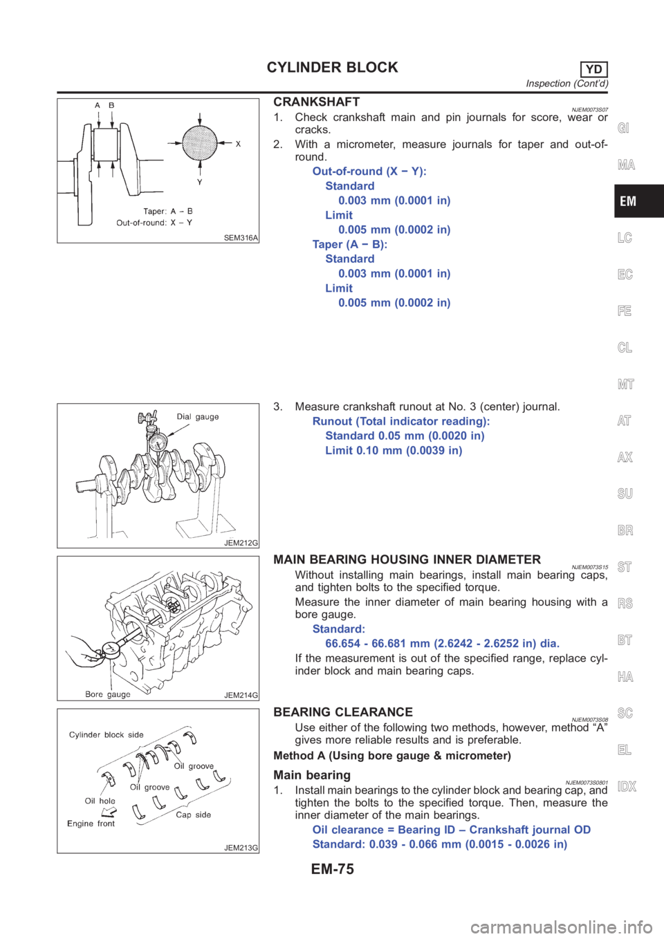
SEM316A
CRANKSHAFTNJEM0073S071. Check crankshaft main and pin journals for score, wear or
cracks.
2. With a micrometer, measure journals for taper and out-of-
round.
Out-of-round (X − Y):
Standard
0.003 mm (0.0001 in)
Limit
0.005 mm (0.0002 in)
Ta p e r ( A − B ) :
Standard
0.003 mm (0.0001 in)
Limit
0.005 mm (0.0002 in)
JEM212G
3. Measure crankshaft runout at No. 3 (center) journal.
Runout (Total indicator reading):
Standard 0.05 mm (0.0020 in)
Limit 0.10 mm (0.0039 in)
JEM214G
MAIN BEARING HOUSING INNER DIAMETERNJEM0073S15Without installing main bearings, install main bearing caps,
and tighten bolts to the specified torque.
Measure the inner diameter of main bearing housing with a
bore gauge.
Standard:
66.654 - 66.681 mm (2.6242 - 2.6252 in) dia.
If the measurement is out of the specified range, replace cyl-
inder block and main bearing caps.
JEM213G
BEARING CLEARANCENJEM0073S08Use either of the following two methods, however, method “A”
gives more reliable results and is preferable.
Method A (Using bore gauge & micrometer)
Main bearingNJEM0073S08011. Install main bearings to the cylinder block and bearing cap, and
tighten the bolts to the specified torque. Then, measure the
inner diameter of the main bearings.
Oil clearance = Bearing ID – Crankshaft journal OD
Standard: 0.039 - 0.066 mm (0.0015 - 0.0026 in)
GI
MA
LC
EC
FE
CL
MT
AT
AX
SU
BR
ST
RS
BT
HA
SC
EL
IDX
CYLINDER BLOCKYD
Inspection (Cont’d)
EM-75
Page 260 of 3189

2. If the value is out of the specified range, select main bearings
to obtain the specified oil clearance, based on the measure-
ments of the main bearing housing inner diameter and crank-
shaft journal outer diameter.
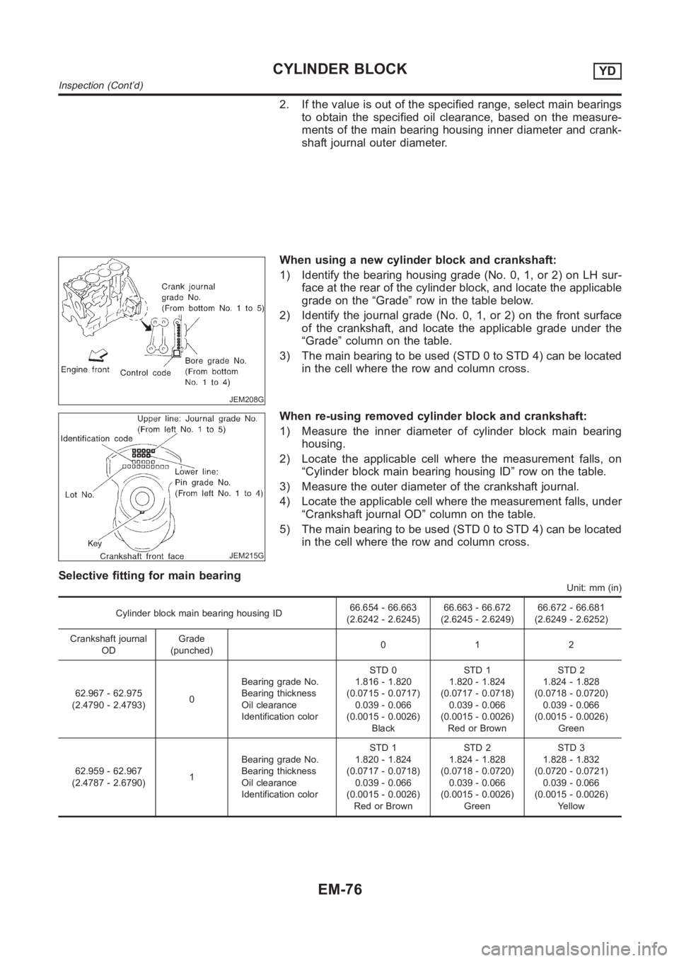
JEM208G
When using a new cylinder block and crankshaft:
1) Identify the bearing housing grade (No. 0, 1, or 2) on LH sur-
face at the rear of the cylinder block, and locate the applicable
grade on the “Grade” row in the table below.
2) Identify the journal grade (No. 0, 1, or 2) on the front surface
of the crankshaft, and locate the applicable grade under the
“Grade” column on the table.
3) The main bearing to be used (STD 0 to STD 4) can be located
in the cell where the row and column cross.
JEM215G
When re-using removed cylinder block and crankshaft:
1) Measure the inner diameter of cylinder block main bearing
housing.
2) Locate the applicable cell where the measurement falls, on
“Cylinder block main bearing housing ID” row on the table.
3) Measure the outer diameter of the crankshaft journal.
4) Locate the applicable cell where the measurement falls, under
“Crankshaft journal OD” column on the table.
5) The main bearing to be used (STD 0 to STD 4) can be located
in the cell where the row and column cross.
Selective fitting for main bearing
Unit: mm (in)
Cylinder block main bearing housing ID66.654 - 66.663
(2.6242 - 2.6245)66.663 - 66.672
(2.6245 - 2.6249)66.672 - 66.681
(2.6249 - 2.6252)
Crankshaft journal
ODGrade
(punched)012
62.967 - 62.975
(2.4790 - 2.4793)0Bearing grade No.
Bearing thickness
Oil clearance
Identification colorSTD 0
1.816 - 1.820
(0.0715 - 0.0717)
0.039 - 0.066
(0.0015 - 0.0026)
BlackSTD 1
1.820 - 1.824
(0.0717 - 0.0718)
0.039 - 0.066
(0.0015 - 0.0026)
Red or BrownSTD 2
1.824 - 1.828
(0.0718 - 0.0720)
0.039 - 0.066
(0.0015 - 0.0026)
Green
62.959 - 62.967
(2.4787 - 2.6790)1Bearing grade No.
Bearing thickness
Oil clearance
Identification colorSTD 1
1.820 - 1.824
(0.0717 - 0.0718)
0.039 - 0.066
(0.0015 - 0.0026)
Red or BrownSTD 2
1.824 - 1.828
(0.0718 - 0.0720)
0.039 - 0.066
(0.0015 - 0.0026)
GreenSTD 3
1.828 - 1.832
(0.0720 - 0.0721)
0.039 - 0.066
(0.0015 - 0.0026)
Yellow
CYLINDER BLOCKYD
Inspection (Cont’d)
EM-76
Page 277 of 3189

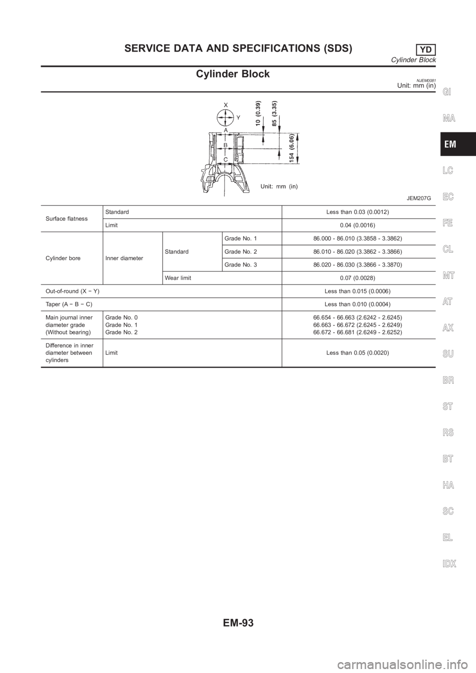
Cylinder BlockNJEM0081Unit: mm (in)
JEM207G
Surface flatnessStandardLess than 0.03 (0.0012)
Limit0.04 (0.0016)
Cylinder bore Inner diameterStandardGrade No. 1 86.000 - 86.010 (3.3858 - 3.3862)
Grade No. 2 86.010 - 86.020 (3.3862 - 3.3866)
Grade No. 3 86.020 - 86.030 (3.3866 - 3.3870)
Wear limit 0.07 (0.0028)
Out-of-round (X − Y)Less than 0.015 (0.0006)
Taper (A−B−C)Less than 0.010 (0.0004)
Main journal inner
diameter grade
(Without bearing)Grade No. 0
Grade No. 1
Grade No. 266.654 - 66.663 (2.6242 - 2.6245)
66.663 - 66.672 (2.6245 - 2.6249)
66.672 - 66.681 (2.6249 - 2.6252)
Difference in inner
diameter between
cylindersLimitLess than 0.05 (0.0020)
GI
MA
LC
EC
FE
CL
MT
AT
AX
SU
BR
ST
RS
BT
HA
SC
EL
IDX
SERVICE DATA AND SPECIFICATIONS (SDS)YD
Cylinder Block
EM-93
Page 333 of 3189

EC-3
C
D
E
F
G
H
I
J
K
L
M
ECA Component Inspection ......................................... 204
Removal and Installation ...................................... 204
DTC P0222, P0223 TP SENSOR ........................... 205
Component Description ........................................ 205
CONSULT-II Reference Value in Data Monitor Mode
. 205
On Board Diagnosis Logic ................................... 205
DTC Confirmation Procedure ............................... 205
Wiring Diagram .................................................... 207
Diagnostic Procedure ........................................... 208
Component Inspection ......................................... 210
Removal and Installation ...................................... 210
DTC P0226 APP SENSOR ......................................211
Component Description ......................................... 211
CONSULT-II Reference Value in Data Monitor Mode
.. 211
On Board Diagnosis Logic .................................... 211
DTC Confirmation Procedure ................................ 211
Wiring Diagram .................................................... 213
Diagnostic Procedure ........................................... 214
Component Inspection ......................................... 216
Removal and Installation ...................................... 217
DTC P0227, P0228 APP SENSOR ........................ 218
Component Description ........................................ 218
CONSULT-II Reference Value in Data Monitor Mode
. 218
On Board Diagnosis Logic ................................... 218
DTC Confirmation Procedure ............................... 218
Wiring Diagram .................................................... 220
Diagnostic Procedure ........................................... 221
Component Inspection ......................................... 223
Removal and Installation ...................................... 224
DTC P0300 - P0304 MULTIPLE CYLINDER MIS-
FIRE, NO. 1 - 4 CYLINDER MISFIRE ..................... 225
On Board Diagnosis Logic ................................... 225
DTC Confirmation Procedure ............................... 225
Diagnostic Procedure ........................................... 226
DTC P0327, P0328 KS ........................................... 230
Component Description ........................................ 230
On Board Diagnosis Logic ................................... 230
DTC Confirmation Procedure ............................... 230
Wiring Diagram .................................................... 231
Diagnostic Procedure ........................................... 232
Component Inspection ......................................... 233
Removal and Installation ...................................... 233
DTC P0335 CKP SENSOR (POS) .......................... 234
Component Description ........................................ 234
CONSULT-II Reference Value in Data Monitor Mode
. 234
On Board Diagnosis Logic ................................... 234
DTC Confirmation Procedure ............................... 234
Wiring Diagram ...................................................
. 235
Diagnostic Procedure ........................................... 236
Component Inspection ......................................... 238
Removal and Installation ...................................... 239
DTC P0340 CMP SENSOR (PHASE) ..................... 240
Component Description ........................................ 240
On Board Diagnosis Logic ................................... 240
DTC Confirmation Procedure ............................... 240Wiring Diagram .....................................................241
Diagnostic Procedure ...........................................242
Component Inspection ..........................................244
Removal and Installation ......................................245
DTC P0420 THREE WAY CATALYST FUNCTION . 246
On Board Diagnosis Logic ....................................246
DTC Confirmation Procedure ...............................246
Overall Function Check ........................................247
Diagnostic Procedure ...........................................248
DTC P0444 EVAP CANISTER PURGE VOLUME
CONTROL SOLENOID VALVE ...............................251
Description ............................................................251
CONSULT-II Reference Value in Data Monitor Mode
.251
On Board Diagnosis Logic ....................................252
DTC Confirmation Procedure ...............................252
Wiring Diagram .....................................................253
Diagnostic Procedure ...........................................254
Component Inspection ..........................................256
Removal and Installation ......................................256
DTC P0500 VSS ......................................................257
Description ............................................................257
On Board Diagnosis Logic ....................................257
DTC Confirmation Procedure ...............................257
Overall Function Check ........................................258
Diagnostic Procedure ...........................................259
DTC P0550 PSP SENSOR .....................................260
Component Description ........................................260
CONSULT-II Reference Value in Data Monitor Mode
.260
On Board Diagnosis Logic ....................................260
DTC Confirmation Procedure ...............................260
Wiring Diagram .....................................................261
Diagnostic Procedure ...........................................262
Component Inspection ..........................................264
DTC P0605 ECM .....................................................265
Component Description ........................................265
On Board Diagnosis Logic ....................................265
DTC Confirmation Procedure ...............................265
Diagnostic Procedure ...........................................266
DTC P1065 ECM POWER SUPPLY .......................268
Component Description ........................................268
On Board Diagnosis Logic ....................................268
DTC Confirmation Procedure ...............................268
Wiring Diagram .....................................................269
Diagnostic Procedure ...........................................270
DTC P1111 IVT CONTROL SOLENOID VALVE .....272
Component Description ........................................272
CONSULT-II Reference Value in Data Monitor Mode
.272
On Board Diagnosis Logic ....................................272
DTC Confirmation Procedure ...............................272
Wiring Diagram .....................................................273
Diagnostic Procedure ...........................................274
Component Inspection ..........................................275
Removal and Installation ......................................275
DTC P1121 ELECTRIC THROTTLE CONTROL
ACTUATOR .............................................................276
Component Description ........................................276
Page 570 of 3189
![NISSAN ALMERA N16 2003 Electronic Repair Manual EC-240
[QG (WITH EURO-OBD)]
DTC P0340 CMP SENSOR (PHASE)
DTC P0340 CMP SENSOR (PHASE)
PFP:23731
Component DescriptionEBS00K8C
The camshaft position sensor (PHASE) senses the retraction with
in NISSAN ALMERA N16 2003 Electronic Repair Manual EC-240
[QG (WITH EURO-OBD)]
DTC P0340 CMP SENSOR (PHASE)
DTC P0340 CMP SENSOR (PHASE)
PFP:23731
Component DescriptionEBS00K8C
The camshaft position sensor (PHASE) senses the retraction with
in](/manual-img/5/57350/w960_57350-569.png)
EC-240
[QG (WITH EURO-OBD)]
DTC P0340 CMP SENSOR (PHASE)
DTC P0340 CMP SENSOR (PHASE)
PFP:23731
Component DescriptionEBS00K8C
The camshaft position sensor (PHASE) senses the retraction with
intake valve camshaft to identify a particular cylinder. The camshaft
position sensor (PHASE) senses the piston position.
When the crankshaft position sensor (POS) system becomes inoper-
ative, the camshaft position sensor (PHASE) provides various con-
trols of engine parts instead, utilizing timing of cylinder identification
signals.
The sensor consists of a permanent magnet and Hall IC.
When engine is running, the high and low parts of the teeth cause
the gap with the sensor to change.
The changing gap causes the magnetic field near the sensor to
change.
Due to the changing magnetic field, the voltage from the sensor changes.
On Board Diagnosis LogicEBS00K8D
DTC Confirmation ProcedureEBS00K8E
NOTE:
If “DTC Confirmation Procedure” has been previously conducted, always turn ignition switch “OFF” and wait at
least 10 seconds before conducting the next test.
TESTING CONDITION:
Before performing the following procedure, confirm that battery voltage is more than 10.5V with igni-
tion switch “ON”.
WITH CONSULT-II
1. Turn ignition switch “ON”.
2. Select “DATA MONITOR” mode with CONSULT-II.
3. Crank engine for at least 2 seconds and run it for at least 5 sec-
onds at idle speed.
4. If 1st trip DTC is detected, go to EC-242, "
Diagnostic Procedure"
.
If 1st trip DTC is not detected, go to next step.
5. Maintain engine speed at more than 800 rpm for at least 5 sec-
onds.
6. If 1st trip DTC is detected, go to EC-242, "
Diagnostic Procedure"
.
WITH GST
Follow the procedure “WITH CONSULT-II” above.
PBIB0562E
DTC No. Trouble diagnosis name DTC detecting condition Possible cause
P0340
0340Camshaft position sensor
(PHASE) circuit
●The cylinder No. signal is not sent to ECM
for the first few seconds during engine
cranking.
●The cylinder No. signal is not set to ECM
during engine running.
●The cylinder No. signal is not in the normal
pattern during engine running.
●Harness or connectors
(The sensor circuit is open or shorted.)
●Camshaft position sensor (PHASE)
●Camshaft (Intake)
●Starter motor (Refer to SC-13.)
●Starting system circuit (Refer to SC-13.)
●Dead (Weak) battery
SEF013Y
Page 572 of 3189
![NISSAN ALMERA N16 2003 Electronic Repair Manual EC-242
[QG (WITH EURO-OBD)]
DTC P0340 CMP SENSOR (PHASE)
Specification data are reference values and are measured between each terminal and ground.
CAUTION:
Do not use ECM ground terminals when measur NISSAN ALMERA N16 2003 Electronic Repair Manual EC-242
[QG (WITH EURO-OBD)]
DTC P0340 CMP SENSOR (PHASE)
Specification data are reference values and are measured between each terminal and ground.
CAUTION:
Do not use ECM ground terminals when measur](/manual-img/5/57350/w960_57350-571.png)
EC-242
[QG (WITH EURO-OBD)]
DTC P0340 CMP SENSOR (PHASE)
Specification data are reference values and are measured between each terminal and ground.
CAUTION:
Do not use ECM ground terminals when measuring input/output voltage. Doing so may result in dam-
age to the ECM's transistor. Use a ground other than ECM terminals, such as the ground.
: Average voltage for pulse signal (Actual pulse signal can be confirmed by oscilloscope.)
Diagnostic ProcedureEBS00K8G
1. CHECK STARTING SYSTEM
Turn ignition switch to “START” position.
Ye s o r N o
Yes >> GO TO 2.
No >> Check starting system. (Refer to SC-13.)
2. RETIGHTEN GROUND SCREWS
1. Turn ignition switch “OFF”.
2. Loosen and retighten engine ground screws.
>> GO TO 3.
TERMI-
NAL
NO.WIRE
COLORITEM CONDITION DATA (DC Voltage)
14 RCamshaft position
sensor (PHASE)[Engine is running]
●Warm-up condition
●Idle speed1.0 - 4.0V
[Engine is running]
●Engine speed is 2,000 rpm.1.0 - 4.0V
29 BCamshaft position
sensor (PHASE)
ground[Engine is running]
●Idle speedApproximately 0V
PBIB0525E
PBIB0526E
Does the engine turn over?
Does the starter motor operate?
MBIB0095E
Page 1696 of 3189
![NISSAN ALMERA N16 2003 Electronic Repair Manual AT-240
[EURO-OBD]
TROUBLE DIAGNOSES FOR SYMPTOMS
4. CHECK OVERDRIVE CONTROL SWITCH CIRCUIT (WITHOUT CONSULT-II)
Without CONSULT-II
1. Turn ignition switch to “ON” position.
(Do not start engine.)
NISSAN ALMERA N16 2003 Electronic Repair Manual AT-240
[EURO-OBD]
TROUBLE DIAGNOSES FOR SYMPTOMS
4. CHECK OVERDRIVE CONTROL SWITCH CIRCUIT (WITHOUT CONSULT-II)
Without CONSULT-II
1. Turn ignition switch to “ON” position.
(Do not start engine.)](/manual-img/5/57350/w960_57350-1695.png)
AT-240
[EURO-OBD]
TROUBLE DIAGNOSES FOR SYMPTOMS
4. CHECK OVERDRIVE CONTROL SWITCH CIRCUIT (WITHOUT CONSULT-II)
Without CONSULT-II
1. Turn ignition switch to “ON” position.
(Do not start engine.)
2. Check voltage between A/T device connector terminal 2 and ground when overdrive control switch is “ON”
and “OFF”.
OK or NG
OK >> GO TO 6
NG >> Check the following items:
●Overdrive control switch (Refer to AT-242, "COMPONENT INSPECTION" .)
●Harness for short or open between TCM and overdrive control switch
●Harness of ground circuit for overdrive control switch for short or open
Voltage:
Switch position “ON”:
Battery voltage
Switch position “OFF”:
1V or less