2003 NISSAN ALMERA N16 change time
[x] Cancel search: change timePage 1223 of 3189

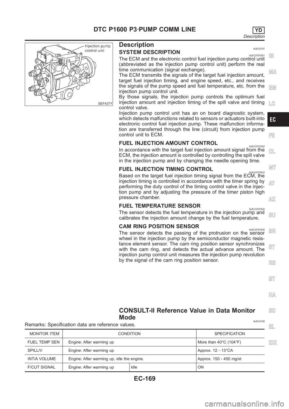
SEF437Y
DescriptionNJEC0707SYSTEM DESCRIPTIONNJEC0707S01The ECM and the electronic control fuel injection pump control unit
(abbreviated as the injection pump control unit) perform the real
time communication (signal exchange).
The ECM transmits the signals of the target fuel injection amount,
target fuel injection timing, and engine speed, etc., and receives
the signals of the pump speed and fuel temperature, etc. from the
injection pump control unit.
By those signals, the injection pump controls the optimum fuel
injection amount and injection timing of the spill valve and timing
control valve.
Injection pump control unit has an on board diagnostic system,
which detects malfunctions related to sensors or actuators built-into
electronic control fuel injection pump. These malfunction informa-
tion are transferred through the line (circuit) from injection pump
control unit to ECM.
FUEL INJECTION AMOUNT CONTROLNJEC0707S02In accordance with the target fuel injection amount signal from the
ECM, the injection amount is controlled by controlling the spill valve
in the injection pump and by changing the needle opening time.
FUEL INJECTION TIMING CONTROLNJEC0707S03Based on the target fuel injection timing signal from the ECM, the
injection timing is controlled in accordance with the timer spring by
performing the duty control of the timing control valve in the injec-
tion pump and by adjusting the pressure of the timer piston high
pressure chamber.
FUEL TEMPERATURE SENSORNJEC0707S04The sensor detects the fuel temperature in the injection pump and
calibrates the injection amount change by the fuel temperature.
CAM RING POSITION SENSORNJEC0707S05The sensor detects the passing of the protrusion on the sensor
wheel in the injection pump by the semiconductor magnetic resis-
tance element sensor. The cam ring position sensor synchronizes
with the cam ring, and detects the actual advance amount. The
injection pump control unit measures the injection pump revolution
by the signal of the cam ring position sensor.
CONSULT-II Reference Value in Data Monitor
Mode
NJEC0708Remarks: Specification data are reference values.
MONITOR ITEM CONDITION SPECIFICATION
FUEL TEMP SEN Engine: After warming up More than 40°C (104°F)
SPILL/V Engine: After warming up Approx. 12 - 13°CA
INT/A VOLUME Engine: After warming up, idle the engine. Approx. 150 - 450 mg/st
F/CUT SIGNAL Engine: After warming up Idle ON
GI
MA
EM
LC
FE
CL
MT
AT
AX
SU
BR
ST
RS
BT
HA
SC
EL
IDX
DTC P1600 P3·PUMP COMM LINEYD
Description
EC-169
Page 1239 of 3189

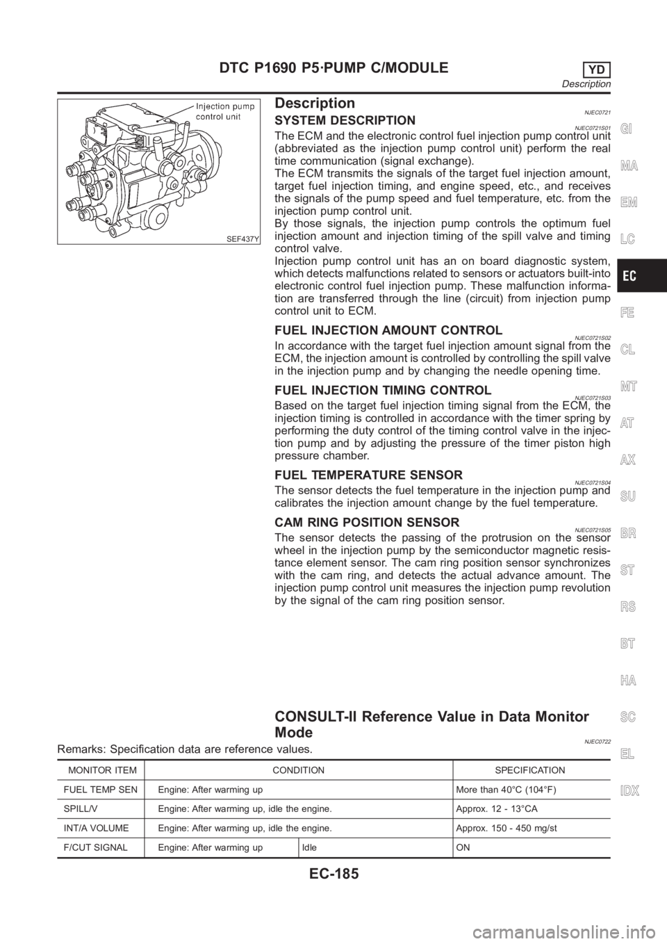
SEF437Y
DescriptionNJEC0721SYSTEM DESCRIPTIONNJEC0721S01The ECM and the electronic control fuel injection pump control unit
(abbreviated as the injection pump control unit) perform the real
time communication (signal exchange).
The ECM transmits the signals of the target fuel injection amount,
target fuel injection timing, and engine speed, etc., and receives
the signals of the pump speed and fuel temperature, etc. from the
injection pump control unit.
By those signals, the injection pump controls the optimum fuel
injection amount and injection timing of the spill valve and timing
control valve.
Injection pump control unit has an on board diagnostic system,
which detects malfunctions related to sensors or actuators built-into
electronic control fuel injection pump. These malfunction informa-
tion are transferred through the line (circuit) from injection pump
control unit to ECM.
FUEL INJECTION AMOUNT CONTROLNJEC0721S02In accordance with the target fuel injection amount signal from the
ECM, the injection amount is controlled by controlling the spill valve
in the injection pump and by changing the needle opening time.
FUEL INJECTION TIMING CONTROLNJEC0721S03Based on the target fuel injection timing signal from the ECM, the
injection timing is controlled in accordance with the timer spring by
performing the duty control of the timing control valve in the injec-
tion pump and by adjusting the pressure of the timer piston high
pressure chamber.
FUEL TEMPERATURE SENSORNJEC0721S04The sensor detects the fuel temperature in the injection pump and
calibrates the injection amount change by the fuel temperature.
CAM RING POSITION SENSORNJEC0721S05The sensor detects the passing of the protrusion on the sensor
wheel in the injection pump by the semiconductor magnetic resis-
tance element sensor. The cam ring position sensor synchronizes
with the cam ring, and detects the actual advance amount. The
injection pump control unit measures the injection pump revolution
by the signal of the cam ring position sensor.
CONSULT-II Reference Value in Data Monitor
Mode
NJEC0722Remarks: Specification data are reference values.
MONITOR ITEM CONDITION SPECIFICATION
FUEL TEMP SEN Engine: After warming up More than 40°C (104°F)
SPILL/V Engine: After warming up, idle the engine. Approx. 12 - 13°CA
INT/A VOLUME Engine: After warming up, idle the engine. Approx. 150 - 450 mg/st
F/CUT SIGNAL Engine: After warming up Idle ON
GI
MA
EM
LC
FE
CL
MT
AT
AX
SU
BR
ST
RS
BT
HA
SC
EL
IDX
DTC P1690 P5·PUMP C/MODULEYD
Description
EC-185
Page 1251 of 3189

DescriptionNJEC0764SYSTEM DESCRIPTIONNJEC0764S01
Sensor Input Signal to ECM ECM Function Actuator
Electronic controlled fuel injection pump Fuel injection signal
EGR volume con-
trolEGR volume control
valve Crankshaft position sensor (TDC) Engine speed
Vehicle speed sensor Vehicle speed
Engine coolant temperature sensor Engine coolant temperature
Ignition switch Start signal
Accelerator position sensor Accelerator position
Mass air flow sensor Amount of intake air
Air conditioner switch Air conditioner operation
Electrical load Electrical load signal
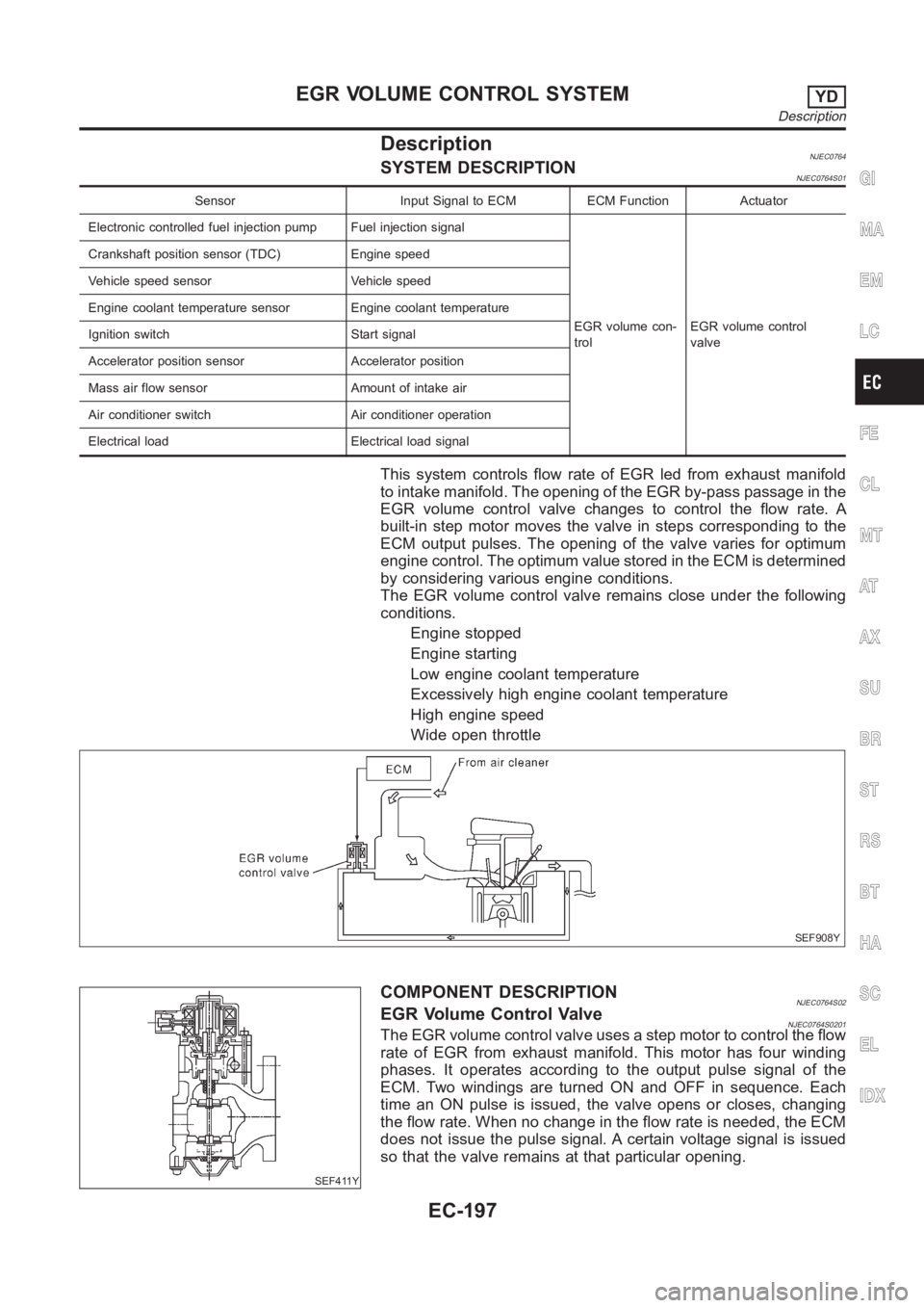
This system controls flow rate of EGR led from exhaust manifold
to intake manifold. The opening of the EGR by-pass passage in the
EGR volume control valve changes to control the flow rate. A
built-in step motor moves the valve in steps corresponding to the
ECM output pulses. The opening of the valve varies for optimum
engine control. The optimum value stored in the ECM is determined
by considering various engine conditions.
The EGR volume control valve remains close under the following
conditions.
Engine stopped
Engine starting
Low engine coolant temperature
Excessively high engine coolant temperature
High engine speed
Wide open throttle
SEF908Y
SEF411Y
COMPONENT DESCRIPTIONNJEC0764S02EGR Volume Control ValveNJEC0764S0201The EGR volume control valve uses a step motor to control the flow
rate of EGR from exhaust manifold. This motor has four winding
phases. It operates according to the output pulse signal of the
ECM. Two windings are turned ON and OFF in sequence. Each
time an ON pulse is issued, the valve opens or closes, changing
the flow rate. When no change in the flow rate is needed, the ECM
does not issue the pulse signal. A certain voltage signal is issued
so that the valve remains at that particular opening.
GI
MA
EM
LC
FE
CL
MT
AT
AX
SU
BR
ST
RS
BT
HA
SC
EL
IDX
EGR VOLUME CONTROL SYSTEMYD
Description
EC-197
Page 1407 of 3189

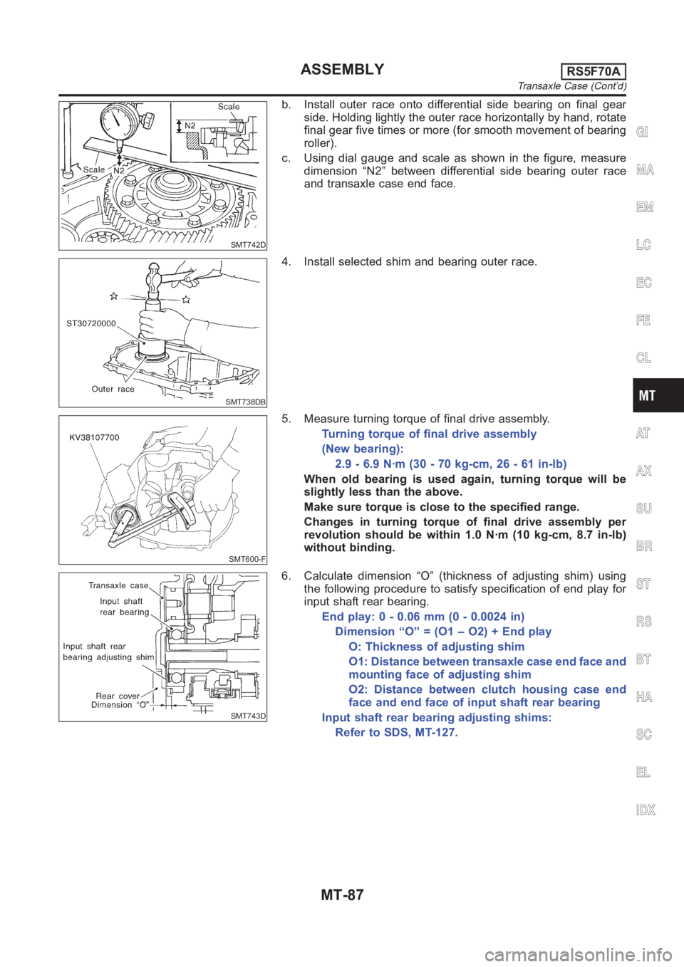
SMT742D
b. Install outer race onto differential side bearing on final gear
side. Holding lightly the outer race horizontally by hand, rotate
final gear five times or more (for smooth movement of bearing
roller).
c. Using dial gauge and scale as shown in the figure, measure
dimension “N2” between differential side bearing outer race
and transaxle case end face.
SMT738DB
4. Install selected shim and bearing outer race.
SMT600-F
5. Measure turning torque of final drive assembly.
Turning torque of final drive assembly
(New bearing):
2.9 - 6.9 N·m (30 - 70 kg-cm, 26 - 61 in-lb)
When old bearing is used again, turning torque will be
slightly less than the above.
Make sure torque is close to the specified range.
Changes in turning torque of final drive assembly per
revolution should be within 1.0 N·m (10 kg-cm, 8.7 in-lb)
without binding.
SMT743D
6. Calculate dimension “O” (thickness of adjusting shim) using
the following procedure to satisfy specification of end play for
input shaft rear bearing.
End play: 0 - 0.06 mm (0 - 0.0024 in)
Dimension “O” = (O1 – O2) + End play
O: Thickness of adjusting shim
O1: Distance between transaxle case end face and
mounting face of adjusting shim
O2: Distance between clutch housing case end
face and end face of input shaft rear bearing
Input shaft rear bearing adjusting shims:
Refer to SDS, MT-127.
GI
MA
EM
LC
EC
FE
CL
AT
AX
SU
BR
ST
RS
BT
HA
SC
EL
IDX
ASSEMBLYRS5F70A
Transaxle Case (Cont’d)
MT-87
Page 1590 of 3189
![NISSAN ALMERA N16 2003 Electronic Repair Manual AT-134
[EURO-OBD]
DTC P0731 A/T 1ST GEAR FUNCTION
DIAGNOSTIC TROUBLE CODE (DTC) CONFIRMATION PROCEDURE
CAUTION:
●Always drive vehicle at a safe speed.
●Be careful not to rev engine into the red zo NISSAN ALMERA N16 2003 Electronic Repair Manual AT-134
[EURO-OBD]
DTC P0731 A/T 1ST GEAR FUNCTION
DIAGNOSTIC TROUBLE CODE (DTC) CONFIRMATION PROCEDURE
CAUTION:
●Always drive vehicle at a safe speed.
●Be careful not to rev engine into the red zo](/manual-img/5/57350/w960_57350-1589.png)
AT-134
[EURO-OBD]
DTC P0731 A/T 1ST GEAR FUNCTION
DIAGNOSTIC TROUBLE CODE (DTC) CONFIRMATION PROCEDURE
CAUTION:
●Always drive vehicle at a safe speed.
●Be careful not to rev engine into the red zone on the tachometer.
NOTE:
If “DIAGNOSTIC TROUBLE CODE CONFIRMATION PROCEDURE” has been previously conducted,
always turn ignition switch “OFF” and wait at least 5 seconds before conducting the next test.
TESTING CONDITION:
Always drive vehicle on a level road to improve the accuracy of test.
After the repair, perform the following procedure to confirm the malfunction is eliminated.
With CONSULT-II
1. Start engine and select “DATA MONITOR” mode for “A/T” with
CONSULT-II.
2. Make sure that output voltage of A/T fluid temperature sensor is
within the range below.
FLUID TEMP SEN: 0.4 - 1.5V
If out of range, drive the vehicle to decrease the voltage (warm
up the fluid) or stop engine to increase the voltage (cool down
the fluid).
3. Select “1ST GR FNCTN P0731” of “DTC WORK SUPPORT”
mode for “A/T” with CONSULT-II and touch “START”.
4. Accelerate vehicle to 15 to 20 km/h (9 to 12 MPH) under the fol-
lowing condition and release the accelerator pedal completely.
THROTTLE POSI: Less than 1.0/8 (at all times during step 4)
Selector lever: D position (OD “ON”)
●Check that “GEAR” shows “2” after releasing pedal.
5. Depress accelerator pedal to WOT (more than 7.0/8 of “THROT-
TLE POSI”) quickly from a speed of 15 to 20 km/h (9 to 12 MPH) until “TESTING” changes to “STOP
VEHICLE” or “COMPLETED”. (It will take approximately 3 seconds.)
If the check result NG appears on CONSULT-II screen, go to AT- 1 3 7 , "
Diagnostic Procedure" .
If “STOP VEHICLE” appears on CONSULT-II screen, go to the following step.
●Check that “GEAR” shows “1” when depressing accelerator pedal to WOT.
SAT014K
SAT021J
SAT971J
Page 1591 of 3189
![NISSAN ALMERA N16 2003 Electronic Repair Manual DTC P0731 A/T 1ST GEAR FUNCTION
AT-135
[EURO-OBD]
D
E
F
G
H
I
J
K
L
MA
B
AT
●If “TESTING” does not appear on CONSULT-II for a long time, select “SELF-DIAGNOSIS” for
“ENGINE” NISSAN ALMERA N16 2003 Electronic Repair Manual DTC P0731 A/T 1ST GEAR FUNCTION
AT-135
[EURO-OBD]
D
E
F
G
H
I
J
K
L
MA
B
AT
●If “TESTING” does not appear on CONSULT-II for a long time, select “SELF-DIAGNOSIS” for
“ENGINE”](/manual-img/5/57350/w960_57350-1590.png)
DTC P0731 A/T 1ST GEAR FUNCTION
AT-135
[EURO-OBD]
D
E
F
G
H
I
J
K
L
MA
B
AT
●If “TESTING” does not appear on CONSULT-II for a long time, select “SELF-DIAGNOSIS” for
“ENGINE”. In case a 1st trip DTC other than P0731 is shown, refer to applicable “TROUBLE DIAG-
NOSIS FOR DTC”.
6. Stop vehicle.
7. Follow the instruction displayed. (Check for normal shifting referring to the table below.)
8. Make sure that “OK” is displayed. (If “NG” is displayed, refer to AT-137, "
Diagnostic Procedure" .)
Refer to AT-515, "
Shift Schedule" .
With GST
Follow the procedure “With CONSULT-II”.
Vehicle conditionGear on actual transmission shift pattern when
screen is changed to 1 → 2 → 3 → 4
No malfunction exists 1 → 2 → 3 → 4
Malfunction for P0731
exists.2→ 2 → 3 → 3
4→ 3 → 3 → 4
Page 1596 of 3189
![NISSAN ALMERA N16 2003 Electronic Repair Manual AT-140
[EURO-OBD]
DTC P0732 A/T 2ND GEAR FUNCTION
DIAGNOSTIC TROUBLE CODE (DTC) CONFIRMATION PROCEDURE
CAUTION:
●Always drive vehicle at a safe speed.
●Be careful not to rev engine into the red zo NISSAN ALMERA N16 2003 Electronic Repair Manual AT-140
[EURO-OBD]
DTC P0732 A/T 2ND GEAR FUNCTION
DIAGNOSTIC TROUBLE CODE (DTC) CONFIRMATION PROCEDURE
CAUTION:
●Always drive vehicle at a safe speed.
●Be careful not to rev engine into the red zo](/manual-img/5/57350/w960_57350-1595.png)
AT-140
[EURO-OBD]
DTC P0732 A/T 2ND GEAR FUNCTION
DIAGNOSTIC TROUBLE CODE (DTC) CONFIRMATION PROCEDURE
CAUTION:
●Always drive vehicle at a safe speed.
●Be careful not to rev engine into the red zone on the tachometer.
NOTE:
If “DIAGNOSTIC TROUBLE CODE CONFIRMATION PROCEDURE” has been previously conducted,
always turn ignition switch “OFF” and wait at least 5 seconds before conducting the next test.
TESTING CONDITION:
Always drive vehicle on a level road to improve the accuracy of test.
After the repair, perform the following procedure to confirm the malfunction is eliminated.
With CONSULT-II
1. Start engine and select “DATA MONITOR” mode for “A/T” with
CONSULT-II.
2. Make sure that output voltage of A/T fluid temperature sensor is
within the range below.
FLUID TEMP SEN: 0.4 - 1.5V
If out of range, drive the vehicle to decrease the voltage (warm
up the fluid) or stop engine to increase the voltage (cool down
the fluid).
3. Select “2ND GR FNCTN P0732” of “DTC WORK SUPPORT”
mode for “A/T” with CONSULT-II and touch “START”.
4. Accelerate vehicle to 35 to 40 km/h (22 to 25 MPH) under the
following condition and release the accelerator pedal com-
pletely.
THROTTLE POSI: Less than 1.0/8 (at all times during step 4)
Selector lever: D position (OD “ON”)
●Check that “GEAR” shows “3” or “4” after releasing pedal.
5. Depress accelerator pedal to WOT (more than 7.0/8 of “THROTTLE POSI”) quickly from a speed of 35 to
40 km/h (22 to 25 MPH) until “TESTING” changes to “STOP VEHICLE” or “COMPLETED”. (It will take
approximately 3 seconds.)
If the check result NG appears on CONSULT-II screen, go to AT- 1 4 3 , "
Diagnostic Procedure" .
If “STOP VEHICLE” appears on CONSULT-II screen, go to following step.
●Check that “GEAR” shows “2” when depressing accelerator pedal to WOT.
●If “TESTING” does not appear on CONSULT-II for a long time, select “SELF-DIAGNOSIS” for
“ENGINE”. In case a 1st trip DTC other than P0732 is shown, refer to applicable “TROUBLE DIAG-
NOSIS FOR DTC”.
SAT014K
SAT021J
SAT971J
Page 1602 of 3189
![NISSAN ALMERA N16 2003 Electronic Repair Manual AT-146
[EURO-OBD]
DTC P0733 A/T 3RD GEAR FUNCTION
DIAGNOSTIC TROUBLE CODE (DTC) CONFIRMATION PROCEDURE
CAUTION:
●Always drive vehicle at a safe speed.
●Be careful not to rev engine into the red zo NISSAN ALMERA N16 2003 Electronic Repair Manual AT-146
[EURO-OBD]
DTC P0733 A/T 3RD GEAR FUNCTION
DIAGNOSTIC TROUBLE CODE (DTC) CONFIRMATION PROCEDURE
CAUTION:
●Always drive vehicle at a safe speed.
●Be careful not to rev engine into the red zo](/manual-img/5/57350/w960_57350-1601.png)
AT-146
[EURO-OBD]
DTC P0733 A/T 3RD GEAR FUNCTION
DIAGNOSTIC TROUBLE CODE (DTC) CONFIRMATION PROCEDURE
CAUTION:
●Always drive vehicle at a safe speed.
●Be careful not to rev engine into the red zone on the tachometer.
NOTE:
If “DIAGNOSTIC TROUBLE CODE CONFIRMATION PROCEDURE” has been previously conducted,
always turn ignition switch “OFF” and wait at least 5 seconds before conducting the next test.
TESTING CONDITION:
Always drive vehicle on a level road to improve the accuracy of test.
After the repair, perform the following procedure to confirm the malfunction is eliminated.
With CONSULT-II
1. Start engine and select “DATA MONITOR” mode for “A/T” with
CONSULT-II.
2. Make sure that output voltage of A/T fluid temperature sensor is
within the range below.
FLUID TEMP SEN: 0.4 - 1.5V
If out of range, drive the vehicle to decrease the voltage (warm
up the fluid) or stop engine to increase the voltage (cool down
the fluid).
3. Select “3RD GR FNCTN P0733” of “DTC WORK SUPPORT”
mode for “A/T” with CONSULT-II and touch “START”.
4. Accelerate vehicle to 55 to 70 km/h (34 to 44 MPH) under the
following condition and release the accelerator pedal com-
pletely.
THROTTLE POSI: Less than 1.0/8 (at all times during step 4)
Selector lever: D position (OD “ON”)
●Check that “GEAR” shows “4” after releasing pedal.
5. Depress accelerator pedal steadily with 3.5/8 - 4.5/8 of “THROT-
TLE POSI” from a speed of 55 to 70 km/h (34 to 44 MPH) until
“TESTING” changes to “STOP VEHICLE” or “COMPLETED”. (It
will take approximately 3 seconds.)
If the check result NG appears on CONSULT-II screen, go to AT- 1 4 9 , "
Diagnostic Procedure" .
If “STOP VEHICLE” appears on CONSULT-II screen, go to following step.
●Check that “GEAR” shows “3” when depressing accelerator pedal with 3.5/8 - 4.5/8 of “THROTTLE
POSI”.
●If “TESTING” does not appear on CONSULT-II for a long time, select “SELF-DIAGNOSIS” for
“ENGINE”. In case a 1st trip DTC other than P0733 is shown, refer to applicable “TROUBLE DIAG-
NOSIS FOR DTC”.
6. Stop vehicle.
SAT014K
SAT021J
SAT971J