2003 NISSAN ALMERA N16 change time
[x] Cancel search: change timePage 1609 of 3189
![NISSAN ALMERA N16 2003 Electronic Repair Manual DTC P0734 A/T 4TH GEAR FUNCTION
AT-153
[EURO-OBD]
D
E
F
G
H
I
J
K
L
MA
B
AT
3. Select “4TH GR FNCTN P0734” of “DTC WORK SUPPORT”
mode for “A/T” with CONSULT-II and touch “START� NISSAN ALMERA N16 2003 Electronic Repair Manual DTC P0734 A/T 4TH GEAR FUNCTION
AT-153
[EURO-OBD]
D
E
F
G
H
I
J
K
L
MA
B
AT
3. Select “4TH GR FNCTN P0734” of “DTC WORK SUPPORT”
mode for “A/T” with CONSULT-II and touch “START�](/manual-img/5/57350/w960_57350-1608.png)
DTC P0734 A/T 4TH GEAR FUNCTION
AT-153
[EURO-OBD]
D
E
F
G
H
I
J
K
L
MA
B
AT
3. Select “4TH GR FNCTN P0734” of “DTC WORK SUPPORT”
mode for “A/T” with CONSULT-II and touch “START”.
4. Accelerate vehicle to 55 to 65 km/h (34 to 40 MPH) under the
following condition and release the accelerator pedal com-
pletely.
THROTTLE POSI: Less than 5.5/8 (at all times during step 4)
Selector lever: D position (OD “ON”)
●Check that “GEAR” shows “3” after releasing pedal.
5. Depress accelerator pedal steadily with 1.0/8 - 2.0/8 of “THROT-
TLE POSI” from a speed of 55 to 65 km/h (34 to 40 MPH) until
“TESTING” has turned to “STOP VEHICLE” or “COMPLETED”.
(It will take approximately 3 seconds.)
If the check result NG appears on CONSULT-II screen, go to AT-155, "
Diagnostic Procedure" .
If “STOP VEHICLE” appears on CONSULT-II screen, go to following step.
●Check that “GEAR” shows “4” when depressing accelerator pedal with 1.0/8 - 2.0/8 of “THROTTLE
POSI”.
●If “TESTING” does not appear on CONSULT-II for a long time, select “SELF-DIAGNOSIS” for
“ENGINE”. In case a 1st trip DTC other than P0734 is shown, refer to applicable “TROUBLE DIAG-
NOSIS FOR DTC”.
6. Stop vehicle.
7. Follow the instruction displayed. (Check for normal shifting referring to the table below.)
8. Make sure that “OK” is displayed. (If “NG” is displayed, go to AT-155, "
Diagnostic Procedure" .)
Refer to AT- 5 1 5 , "
Shift Schedule" .
With GST
Follow the procedure “With CONSULT-II”.
Vehicle conditionGear on actual transmission shift pattern when
screen is changed to 1 → 2 → 3 → 4
No malfunction exists 1 → 2 → 3 → 4
Malfunction for P0734 exists. 1 → 2 → 2 → 1
SAT971J
Page 1989 of 3189
PRECAUTIONS
ATC-9
C
D
E
F
G
H
I
K
L
MA
B
AT C
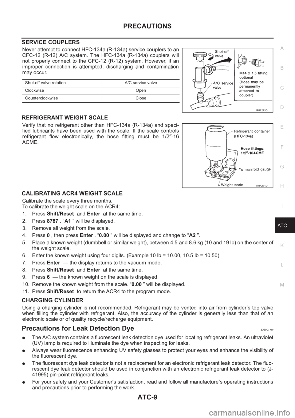
SERVICE COUPLERS
Never attempt to connect HFC-134a (R-134a) service couplers to an
CFC-12 (R-12) A/C system. The HFC-134a (R-134a) couplers will
not properly connect to the CFC-12 (R-12) system. However, if an
improper connection is attempted, discharging and contamination
may occur.
REFRIGERANT WEIGHT SCALE
Verify that no refrigerant other than HFC-134a (R-134a) and speci-
fied lubricants have been used with the scale. If the scale controls
refrigerant flow electronically, the hose fitting must be 1/2″-16
ACME.
CALIBRATING ACR4 WEIGHT SCALE
Calibrate the scale every three months.
To calibrate the weight scale on the ACR4:
1. Press Shift/Reset and Enter at the same time.
2. Press 8787 . “A1 ” will be displayed.
3. Remove all weight from the scale.
4. Press 0 , then press Enter . “0.00 ” will be displayed and change to “A2 ”.
5. Place a known weight (dumbbell or similar weight), between 4.5 and 8.6 kg (10 and 19 lb) on the center of
the weight scale.
6. Enter the known weight using four digits. (Example 10 lb = 10.00, 10.5 lb = 10.50)
7. Press Enter — the display returns to the vacuum mode.
8. Press Shift/Reset and Enter at the same time.
9. Press 6 — the known weight on the scale is displayed.
10. Remove the known weight from the scale. “0.00 ” will be displayed.
11 . P r e s s Shift/Reset to return the ACR4 to the program mode.
CHARGING CYLINDER
Using a charging cylinder is not recommended. Refrigerant may be vented into air from cylinder′s top valve
when filling the cylinder with refrigerant. Also, the accuracy of the cylinder is generally less than that of an
electronic scale or of quality recycle/recharge equipment.
Precautions for Leak Detection DyeEJS001YW
●The A/C system contains a fluorescent leak detection dye used for locating refrigerant leaks. An ultraviolet
(UV) lamp is required to illuminate the dye when inspecting for leaks.
●Always wear fluorescence enhancing UV safety glasses to protect your eyes and enhance the visibility of
the fluorescent dye.
●The fluorescent dye leak detector is not a replacement for an electronic refrigerant leak detector. The fluo-
rescent dye leak detector should be used in conjunction with an electronic refrigerant leak detector to (J-
41995) pin-point refrigerant leaks.
●For your safety and your Customer′s satisfaction, read and follow all manufacture′s operating instructions
and precautions prior to performing the work.
Shut-off valve rotation A/C service valve
Clockwise Open
Counterclockwise Close
RHA273D
RHA274D
Page 2029 of 3189
TROUBLE DIAGNOSIS
ATC-49
C
D
E
F
G
H
I
K
L
MA
B
AT C
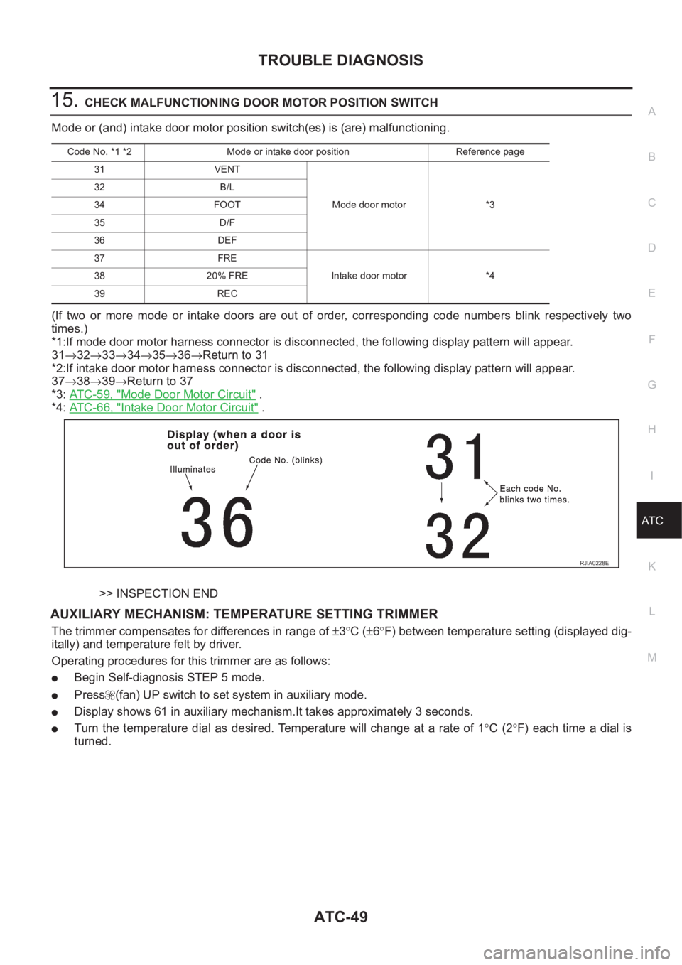
15.CHECK MALFUNCTIONING DOOR MOTOR POSITION SWITCH
Mode or (and) intake door motor position switch(es) is (are) malfunctioning.
(If two or more mode or intake doors are out of order, corresponding code numbers blink respectively two
times.)
*1:If mode door motor harness connector is disconnected, the following display pattern will appear.
31→32→33→34→35→36→Return to 31
*2:If intake door motor harness connector is disconnected, the following display pattern will appear.
37→38→39→Return to 37
*3: AT C - 5 9 , "
Mode Door Motor Circuit" .
*4: AT C - 6 6 , "
Intake Door Motor Circuit" .
>> INSPECTION END
AUXILIARY MECHANISM: TEMPERATURE SETTING TRIMMER
The trimmer compensates for differences in range of ±3°C (±6°F) between temperature setting (displayed dig-
itally) and temperature felt by driver.
Operating procedures for this trimmer are as follows:
●Begin Self-diagnosis STEP 5 mode.
●Press (fan) UP switch to set system in auxiliary mode.
●Display shows 61 in auxiliary mechanism.It takes approximately 3 seconds.
●Turn the temperature dial as desired. Temperature will change at a rate of 1°C (2°F) each time a dial is
turned.
Code No. *1 *2 Mode or intake door position Reference page
31 VENT
Mode door motor *3 32 B/L
34 FOOT
35 D/F
36 DEF
37 FRE
Intake door motor *4 38 20% FRE
39 REC
RJIA0228E
Page 2032 of 3189
ATC-52
TROUBLE DIAGNOSIS
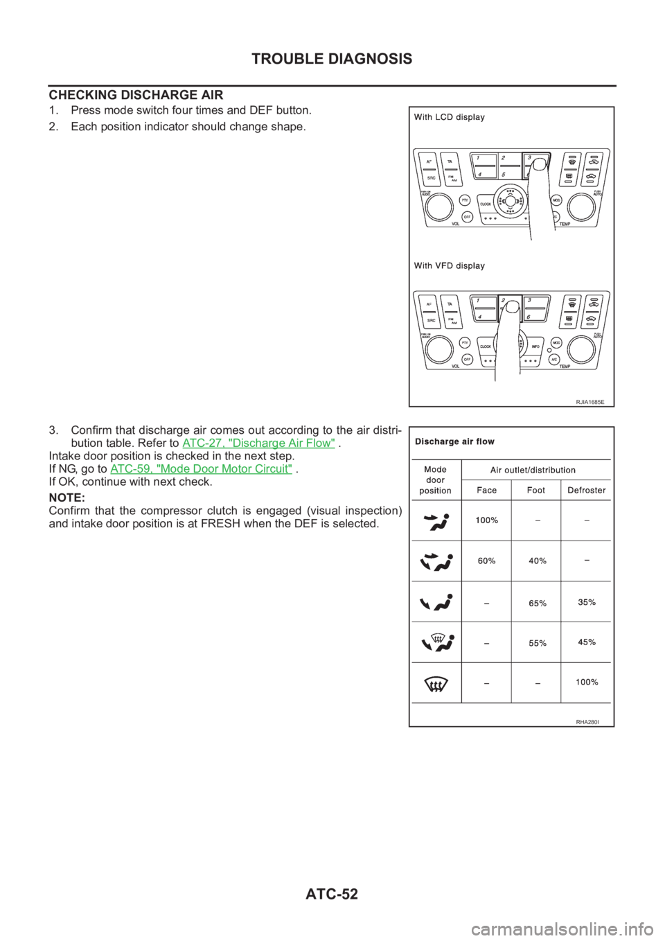
CHECKING DISCHARGE AIR
1. Press mode switch four times and DEF button.
2. Each position indicator should change shape.
3. Confirm that discharge air comes out according to the air distri-
bution table. Refer to ATC-27, "
Discharge Air Flow" .
Intake door position is checked in the next step.
If NG, go to AT C - 5 9 , "
Mode Door Motor Circuit" .
If OK, continue with next check.
NOTE:
Confirm that the compressor clutch is engaged (visual inspection)
and intake door position is at FRESH when the DEF is selected.
RJIA1685E
RHA280I
Page 2033 of 3189
TROUBLE DIAGNOSIS
ATC-53
C
D
E
F
G
H
I
K
L
MA
B
AT C
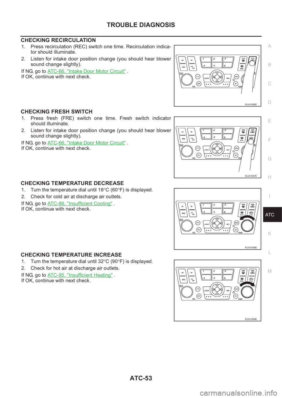
CHECKING RECIRCULATION
1. Press recirculation (REC) switch one time. Recirculation indica-
tor should illuminate.
2. Listen for intake door position change (you should hear blower
sound change slightly).
If NG, go to ATC-66, "
Intake Door Motor Circuit" .
If OK, continue with next check.
CHECKING FRESH SWITCH
1. Press fresh (FRE) switch one time. Fresh switch indicator
should illuminate.
2. Listen for intake door position change (you should hear blower
sound change slightly).
If NG, go to ATC-66, "
Intake Door Motor Circuit" .
If OK, continue with next check.
CHECKING TEMPERATURE DECREASE
1. Turn the temperature dial until 18°C (60°F) is displayed.
2. Check for cold air at discharge air outlets.
If NG, go to ATC-86, "
Insufficient Cooling" .
If OK, continue with next check.
CHECKING TEMPERATURE INCREASE
1. Turn the temperature dial until 32°C (90°F) is displayed.
2. Check for hot air at discharge air outlets.
If NG, go to ATC-95, "
Insufficient Heating" .
If OK, continue with next check.
RJIA1686E
RJIA1687E
RJIA1688E
RJIA1689E
Page 2072 of 3189
ATC-92
TROUBLE DIAGNOSIS
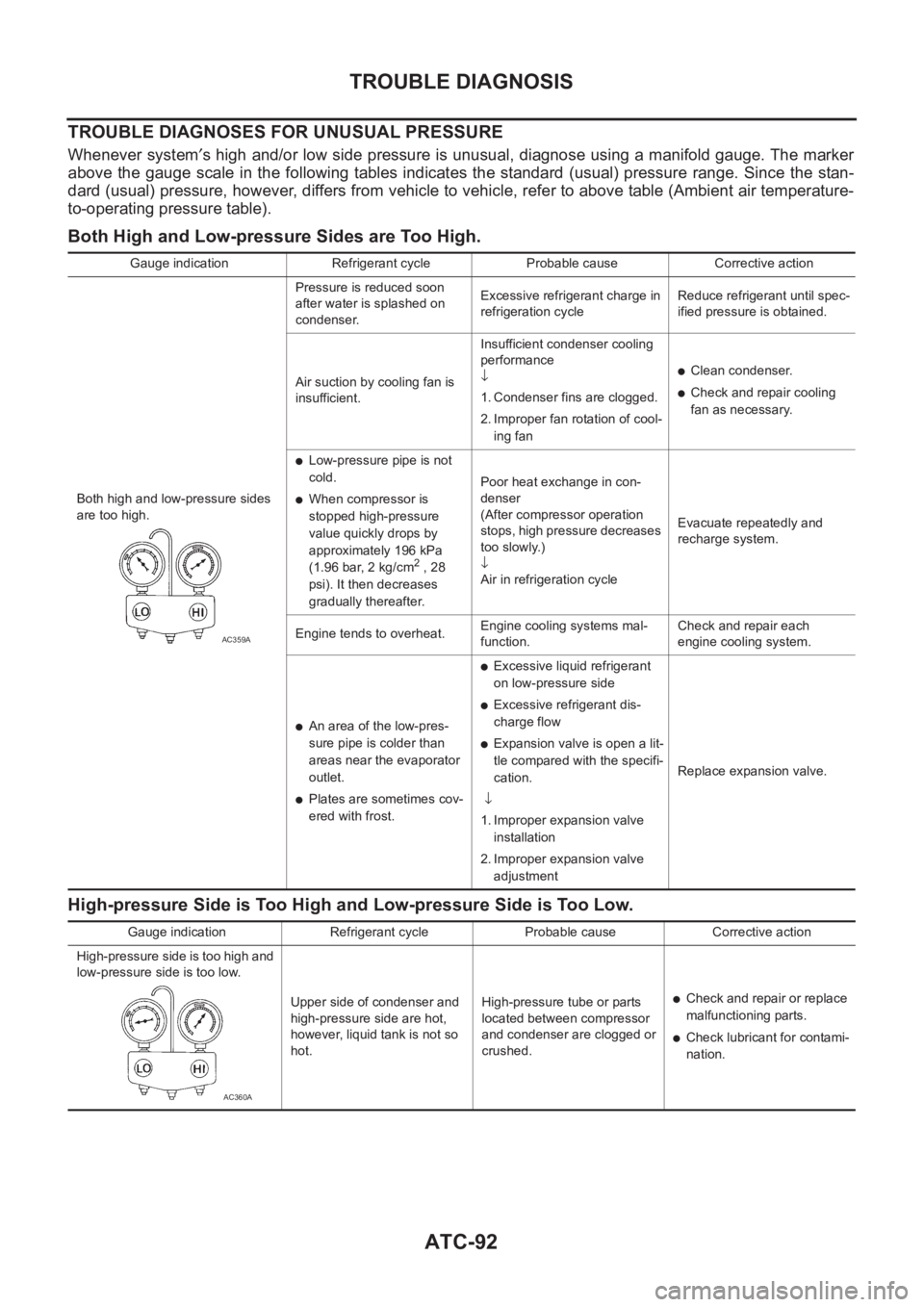
TROUBLE DIAGNOSES FOR UNUSUAL PRESSURE
Whenever system′s high and/or low side pressure is unusual, diagnose using a manifold gauge. The marker
above the gauge scale in the following tables indicates the standard (usual) pressure range. Since the stan-
dard (usual) pressure, however, differs from vehicle to vehicle, refer to above table (Ambient air temperature-
to-operating pressure table).
Both High and Low-pressure Sides are Too High.
High-pressure Side is Too High and Low-pressure Side is Too Low.
Gauge indication Refrigerant cycle Probable cause Corrective action
Both high and low-pressure sides
are too high.Pressure is reduced soon
after water is splashed on
condenser.Excessive refrigerant charge in
refrigeration cycleReduce refrigerant until spec-
ified pressure is obtained.
Air suction by cooling fan is
insufficient.Insufficient condenser cooling
performance
↓
1. Condenser fins are clogged.
2. Improper fan rotation of cool-
ing fan
●Clean condenser.
●Check and repair cooling
fan as necessary.
●Low-pressure pipe is not
cold.
●When compressor is
stopped high-pressure
value quickly drops by
approximately 196 kPa
(1.96 bar, 2 kg/cm
2 , 28
psi). It then decreases
gradually thereafter.Poor heat exchange in con-
denser
(After compressor operation
stops, high pressure decreases
too slowly.)
↓
Air in refrigeration cycleEvacuate repeatedly and
recharge system.
Engine tends to overheat.Engine cooling systems mal-
function.Check and repair each
engine cooling system.
●An area of the low-pres-
sure pipe is colder than
areas near the evaporator
outlet.
●Plates are sometimes cov-
ered with frost.
●Excessive liquid refrigerant
on low-pressure side
●Excessive refrigerant dis-
charge flow
●Expansion valve is open a lit-
tle compared with the specifi-
cation.
↓
1. Improper expansion valve
installation
2. Improper expansion valve
adjustmentReplace expansion valve.
AC359A
Gauge indication Refrigerant cycle Probable cause Corrective action
High-pressure side is too high and
low-pressure side is too low.
Upper side of condenser and
high-pressure side are hot,
however, liquid tank is not so
hot.High-pressure tube or parts
located between compressor
and condenser are clogged or
crushed.
●Check and repair or replace
malfunctioning parts.
●Check lubricant for contami-
nation.
AC360A
Page 2085 of 3189
TROUBLE DIAGNOSIS
ATC-105
C
D
E
F
G
H
I
K
L
MA
B
AT C
Sunload Sensor CircuitEJS001ZX
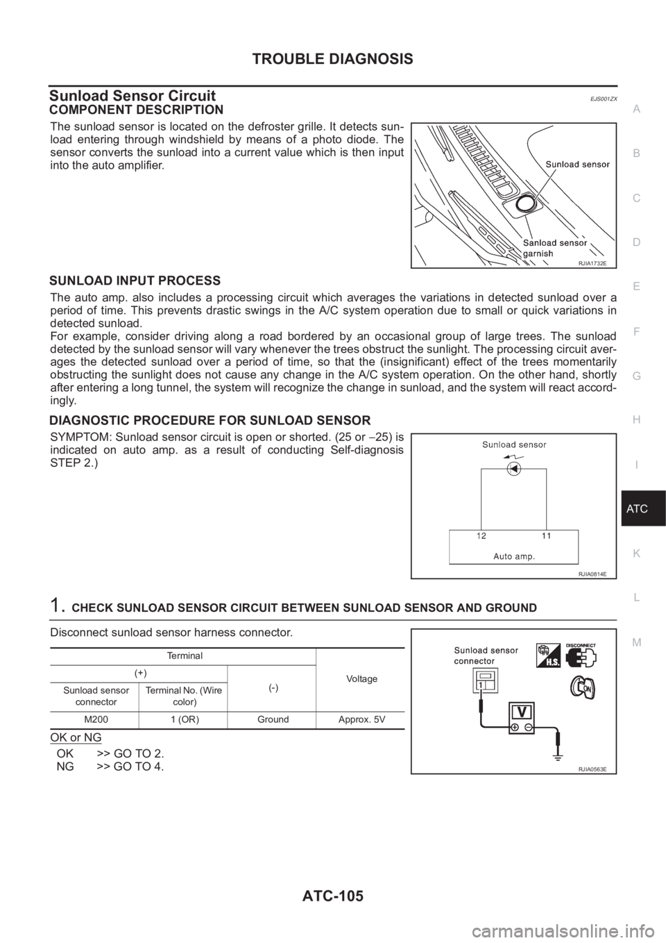
COMPONENT DESCRIPTION
The sunload sensor is located on the defroster grille. It detects sun-
load entering through windshield by means of a photo diode. The
sensor converts the sunload into a current value which is then input
into the auto amplifier.
SUNLOAD INPUT PROCESS
The auto amp. also includes a processing circuit which averages the variations in detected sunload over a
period of time. This prevents drastic swings in the A/C system operation due to small or quick variations in
detected sunload.
For example, consider driving along a road bordered by an occasional group of large trees. The sunload
detected by the sunload sensor will vary whenever the trees obstruct the sunlight. The processing circuit aver-
ages the detected sunload over a period of time, so that the (insignificant) effect of the trees momentarily
obstructing the sunlight does not cause any change in the A/C system operation. On the other hand, shortly
after entering a long tunnel, the system will recognize the change in sunload, and the system will react accord-
ingly.
DIAGNOSTIC PROCEDURE FOR SUNLOAD SENSOR
SYMPTOM: Sunload sensor circuit is open or shorted. (25 or −25) is
indicated on auto amp. as a result of conducting Self-diagnosis
STEP 2.)
1.CHECK SUNLOAD SENSOR CIRCUIT BETWEEN SUNLOAD SENSOR AND GROUND
Disconnect sunload sensor harness connector.
OK or NG
OK >> GO TO 2.
NG >> GO TO 4.
RJIA1732E
RJIA0814E
Te r m i n a l
Voltage (+)
(-)
Sunload sensor
connectorTerminal No. (Wire
color)
M200 1 (OR) Ground Approx. 5V
RJIA0563E
Page 2204 of 3189
SBR002A
SBR365AA
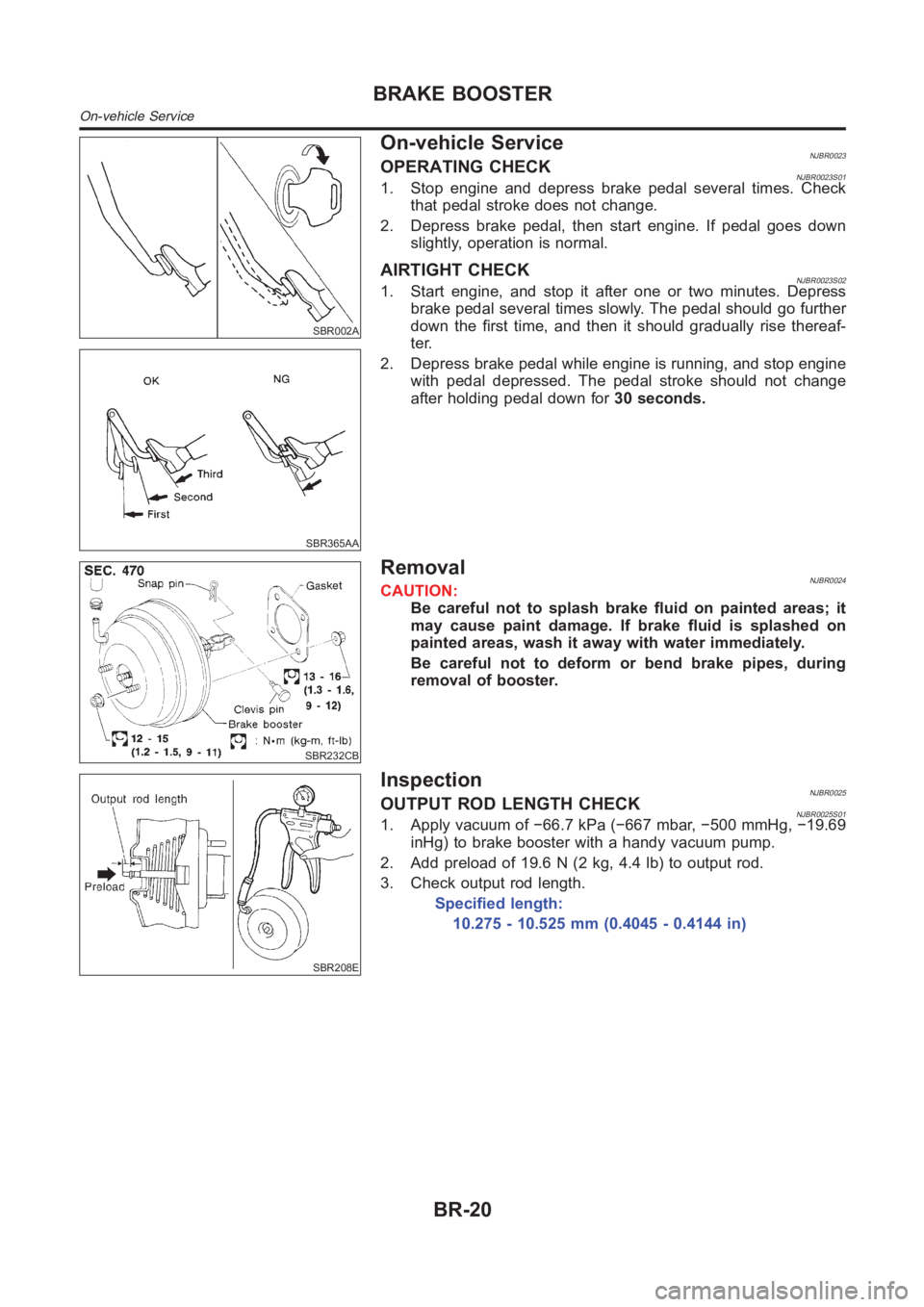
On-vehicle ServiceNJBR0023OPERATING CHECKNJBR0023S011. Stop engine and depress brake pedal several times. Check
that pedal stroke does not change.
2. Depress brake pedal, then start engine. If pedal goes down
slightly, operation is normal.
AIRTIGHT CHECKNJBR0023S021. Start engine, and stop it after one or two minutes. Depress
brake pedal several times slowly. The pedal should go further
down the first time, and then it should gradually rise thereaf-
ter.
2. Depress brake pedal while engine is running, and stop engine
with pedal depressed. The pedal stroke should not change
after holding pedal down for30 seconds.
SBR232CB
RemovalNJBR0024CAUTION:
Be careful not to splash brake fluid on painted areas; it
may cause paint damage. If brake fluid is splashed on
painted areas, wash it away with water immediately.
Be careful not to deform or bend brake pipes, during
removal of booster.
SBR208E
InspectionNJBR0025OUTPUT ROD LENGTH CHECKNJBR0025S011. Apply vacuum of −66.7 kPa (−667 mbar, −500 mmHg, −19.69
inHg) to brake booster with a handy vacuum pump.
2. Add preload of 19.6 N (2 kg, 4.4 lb) to output rod.
3. Check output rod length.
Specified length:
10.275 - 10.525 mm (0.4045 - 0.4144 in)
BRAKE BOOSTER
On-vehicle Service
BR-20