2003 NISSAN ALMERA N16 change time
[x] Cancel search: change timePage 2766 of 3189
SKIA0370E
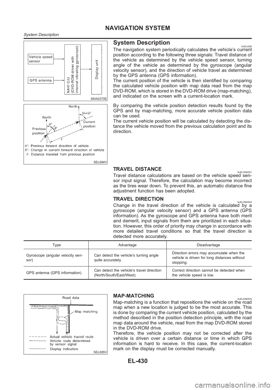
System DescriptionNJEL0592The navigation system periodically calculates the vehicle’s current
position according to the following three signals: Travel distance of
the vehicle as determined by the vehicle speed sensor, turning
angle of the vehicle as determined by the gyroscope (angular
velocity sensor), and the direction of vehicle travel as determined
by the GPS antenna (GPS information).
The current position of the vehicle is then identified by comparing
the calculated vehicle position with map data read from the map
DVD-ROM, which is stored in the DVD-ROM drive (map-matching),
and indicated on the screen with a current-location mark.
SEL684V
By comparing the vehicle position detection results found by the
GPS and by map-matching, more accurate vehicle position data
canbeused.
The current vehicle position will be calculated by detecting the dis-
tance the vehicle moved from the previous calculation point and its
direction.
TRAVEL DISTANCENJEL0592S01Travel distance calculations are based on the vehicle speed sen-
sor input signal. Therefore, the calculation may become incorrect
as the tires wear down. To prevent this, an automatic distance fine
adjustment function has been adopted.
TRAVEL DIRECTIONNJEL0592S02Change in the travel direction of the vehicle is calculated by a
gyroscope (angular velocity sensor) and a GPS antenna (GPS
information). As the gyroscope and GPS antenna have both merit
and demerit, input signals from them are prioritized in each situa-
tion. However, this order of priority may change in accordance with
more detailed travel conditions so that the travel direction is
detected more accurately.
Type Advantage Disadvantage
Gyroscope (angular velocity sen-
sor)Can detect the vehicle’s turning angle
quite accurately.Direction errors may accumulate when the
vehicle is driven for long distances without
stopping.
GPS antenna (GPS information)Can detect the vehicle’s travel direction
(North/South/East/West).Correct direction cannot be detected when
the vehicle speed is low.
SEL685V
MAP-MATCHINGNJEL0592S03Map-matching is a function that repositions the vehicle on the road
map when a new location is judged to be the most accurate. This
is done by comparing the current vehicle position, calculated by the
method described in the position detection principle, with the road
map data around the vehicle, read from the map DVD-ROM stored
in the DVD-ROM drive.
Therefore, the vehicle position may not be corrected after the
vehicle is driven over a certain distance or time in which GPS
information is hard to receive. In this case, the current-location
mark on the display must be corrected manually.
NAVIGATION SYSTEM
System Description
EL-430
Page 2792 of 3189
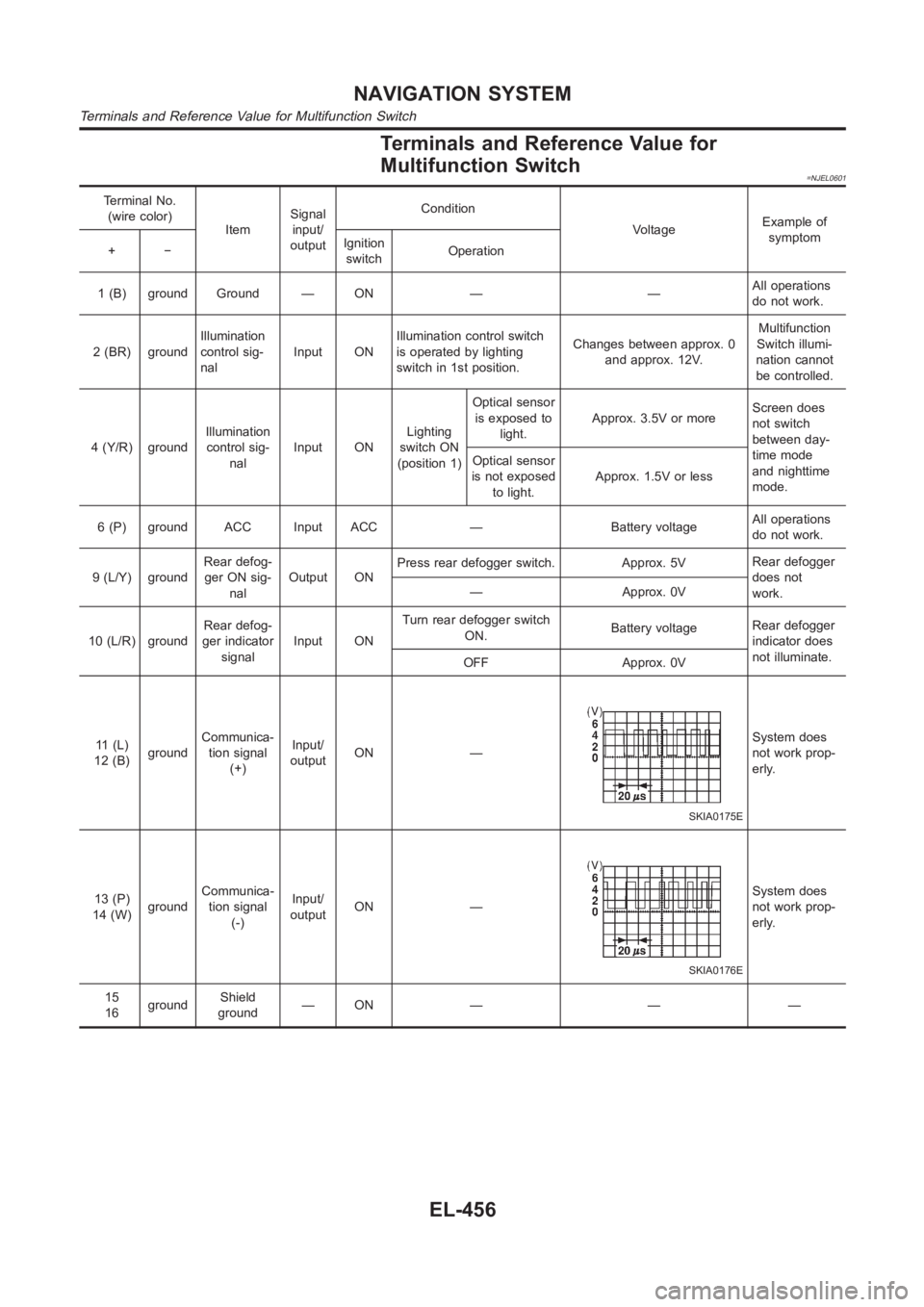
Terminals and Reference Value for
Multifunction Switch
=NJEL0601
Terminal No.
(wire color)
ItemSignal
input/
outputCondition
VoltageExample of
symptom
+−Ignition
switchOperation
1 (B) ground Ground — ON — —All operations
do not work.
2 (BR) groundIllumination
control sig-
nalInput ONIllumination control switch
is operated by lighting
switch in 1st position.Changes between approx. 0
and approx. 12V.Multifunction
Switch illumi-
nation cannot
be controlled.
4 (Y/R) groundIllumination
control sig-
nalInput ONLighting
switch ON
(position 1)Optical sensor
is exposed to
light.Approx. 3.5V or moreScreen does
not switch
between day-
time mode
and nighttime
mode. Optical sensor
is not exposed
to light.Approx. 1.5V or less
6 (P) ground ACC Input ACC — Battery voltageAll operations
do not work.
9 (L/Y) groundRear defog-
ger ON sig-
nalOutput ONPress rear defogger switch. Approx. 5VRear defogger
does not
work. — Approx. 0V
10 (L/R) groundRear defog-
ger indicator
signalInput ONTurn rear defogger switch
ON.Battery voltageRear defogger
indicator does
not illuminate.
OFF Approx. 0V
11 (L)
12 (B)groundCommunica-
tion signal
(+)Input/
outputON —
SKIA0175E
System does
not work prop-
erly.
13 (P)
14 (W)groundCommunica-
tion signal
(-)Input/
outputON —
SKIA0176E
System does
not work prop-
erly.
15
16groundShield
ground—ON — — —
NAVIGATION SYSTEM
Terminals and Reference Value for Multifunction Switch
EL-456
Page 2793 of 3189
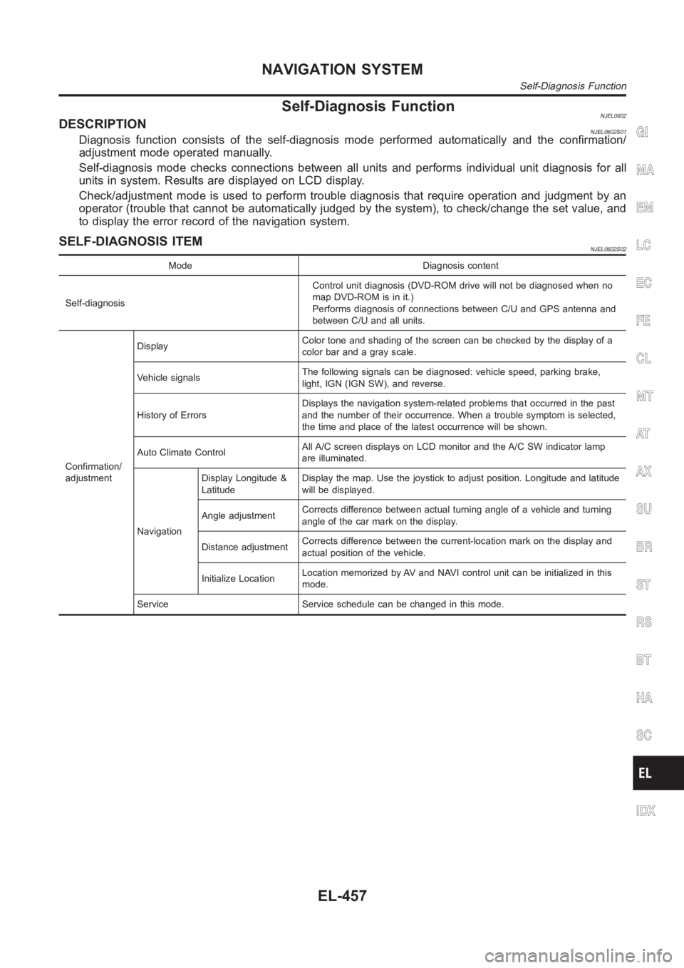
Self-Diagnosis FunctionNJEL0602DESCRIPTIONNJEL0602S01Diagnosis function consists of the self-diagnosis mode performed automatically and the confirmation/
adjustment mode operated manually.
Self-diagnosis mode checks connections between all units and performs individual unit diagnosis for all
units in system. Results are displayed on LCD display.
Check/adjustment mode is used to perform trouble diagnosis that require operation and judgment by an
operator (trouble that cannot be automatically judged by the system), to check/change the set value, and
to display the error record of the navigation system.
SELF-DIAGNOSIS ITEMNJEL0602S02
Mode Diagnosis content
Self-diagnosisControl unit diagnosis (DVD-ROM drive will not be diagnosed when no
map DVD-ROM is in it.)
Performs diagnosis of connections between C/U and GPS antenna and
between C/U and all units.
Confirmation/
adjustmentDisplayColor tone and shading of the screen can be checked by the display of a
color bar and a gray scale.
Vehicle signalsThe following signals can be diagnosed: vehicle speed, parking brake,
light, IGN (IGN SW), and reverse.
History of ErrorsDisplays the navigation system-related problems that occurred in the past
and the number of their occurrence. When a trouble symptom is selected,
the time and place of the latest occurrence will be shown.
Auto Climate ControlAll A/C screen displays on LCD monitor and the A/C SW indicator lamp
are illuminated.
NavigationDisplay Longitude &
LatitudeDisplay the map. Use the joystick to adjust position. Longitude and latitude
will be displayed.
Angle adjustmentCorrects difference between actual turning angle of a vehicle and turning
angle of the car mark on the display.
Distance adjustmentCorrects difference between the current-location mark on the display and
actual position of the vehicle.
Initialize LocationLocation memorized by AV and NAVI control unit can be initialized in this
mode.
Service Service schedule can be changed in this mode.
GI
MA
EM
LC
EC
FE
CL
MT
AT
AX
SU
BR
ST
RS
BT
HA
SC
IDX
NAVIGATION SYSTEM
Self-Diagnosis Function
EL-457
Page 2799 of 3189
SKIA1617E
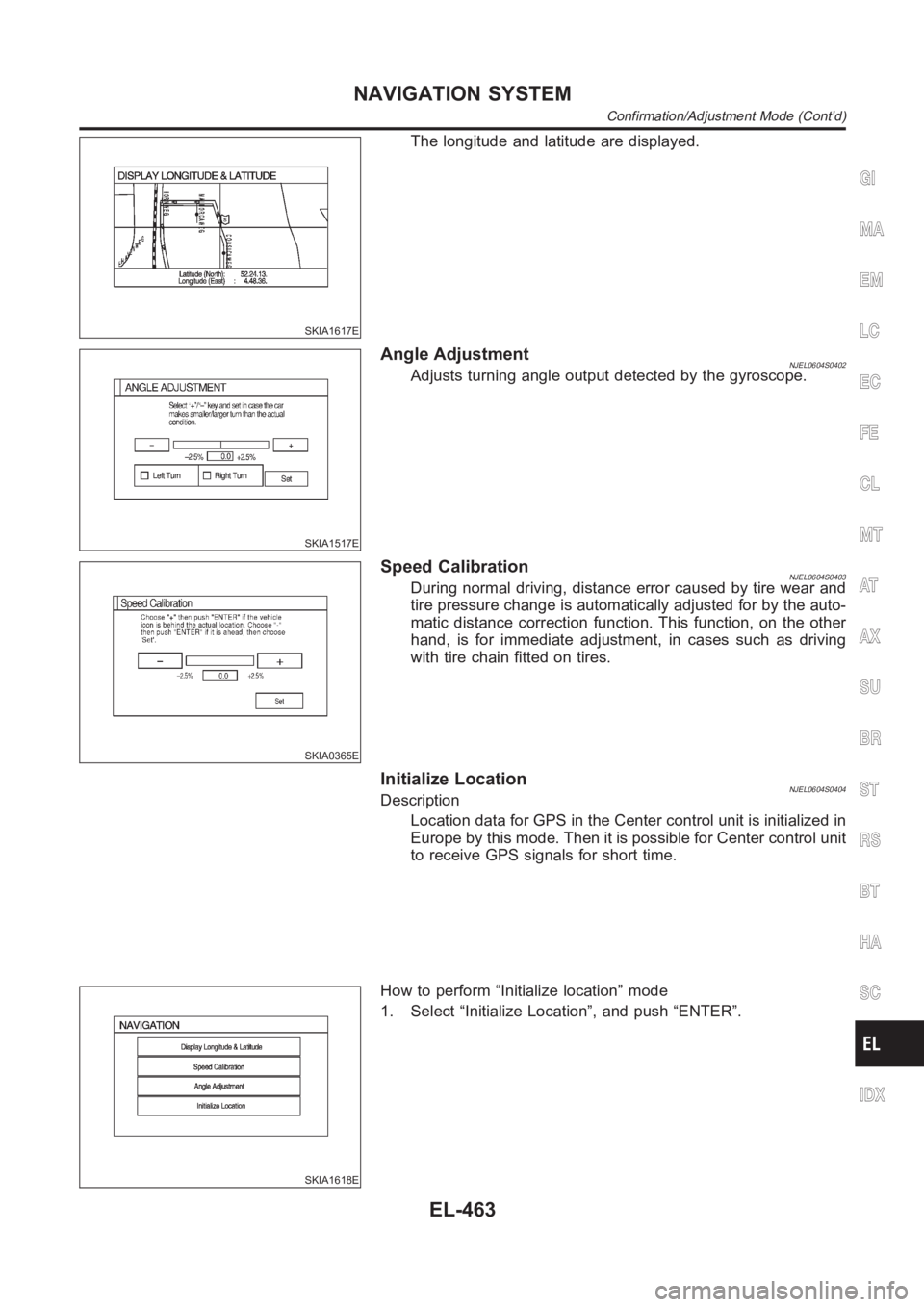
The longitude and latitude are displayed.
SKIA1517E
Angle AdjustmentNJEL0604S0402Adjusts turning angle output detected by the gyroscope.
SKIA0365E
Speed CalibrationNJEL0604S0403During normal driving, distance error caused by tire wear and
tire pressure change is automatically adjusted for by the auto-
matic distance correction function. This function, on the other
hand, is for immediate adjustment, in cases such as driving
with tire chain fitted on tires.
Initialize LocationNJEL0604S0404Description
Location data for GPS in the Center control unit is initialized in
Europe by this mode. Then it is possible for Center control unit
to receive GPS signals for short time.
SKIA1618E
How to perform “Initialize location” mode
1. Select “Initialize Location”, and push “ENTER”.
GI
MA
EM
LC
EC
FE
CL
MT
AT
AX
SU
BR
ST
RS
BT
HA
SC
IDX
NAVIGATION SYSTEM
Confirmation/Adjustment Mode (Cont’d)
EL-463
Page 2800 of 3189
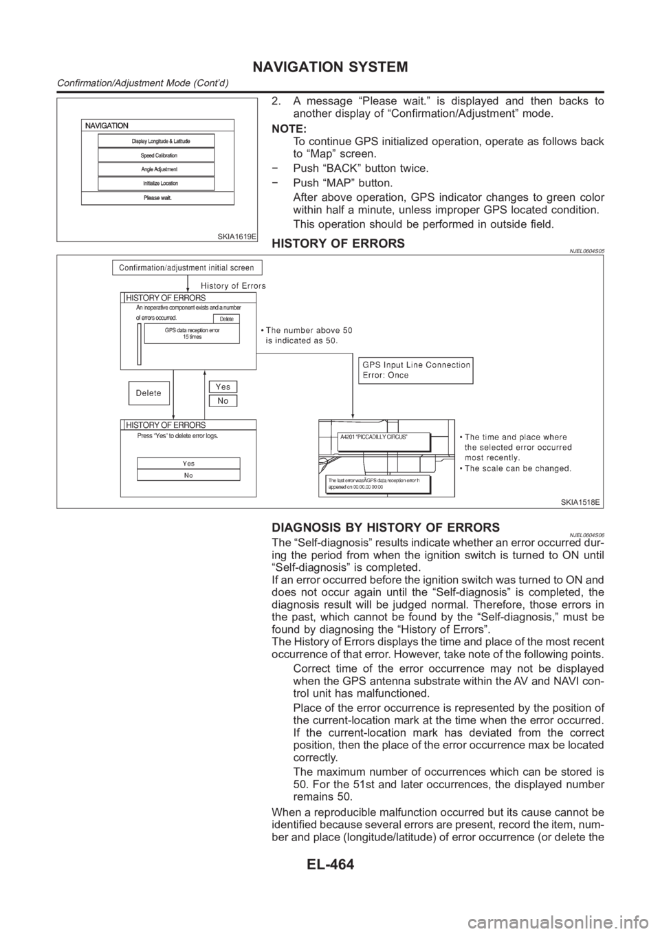
SKIA1619E
2. A message “Please wait.” is displayed and then backs to
another display of “Confirmation/Adjustment” mode.
NOTE:
To continue GPS initialized operation, operate as follows back
to “Map” screen.
− Push “BACK” button twice.
− Push “MAP” button.
After above operation, GPS indicator changes to green color
within half a minute, unless improper GPS located condition.
This operation should be performed in outside field.
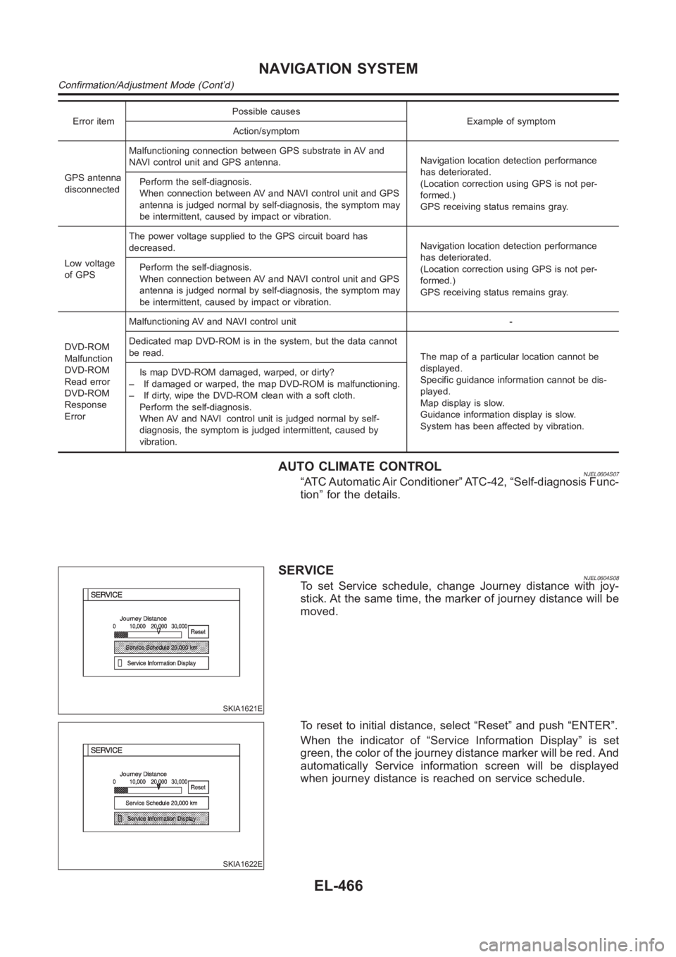
HISTORY OF ERRORSNJEL0604S05
SKIA1518E
DIAGNOSIS BY HISTORY OF ERRORSNJEL0604S06The “Self-diagnosis” results indicate whether an error occurred dur-
ing the period from when the ignition switch is turned to ON until
“Self-diagnosis” is completed.
If an error occurred before the ignition switch was turned to ON and
does not occur again until the “Self-diagnosis” is completed, the
diagnosis result will be judged normal. Therefore, those errors in
the past, which cannot be found by the “Self-diagnosis,” must be
found by diagnosing the “History of Errors”.
The History of Errors displays the time and place of the most recent
occurrence of that error. However, take note of the following points.
Correct time of the error occurrence may not be displayed
when the GPS antenna substrate within the AV and NAVI con-
trol unit has malfunctioned.
Place of the error occurrence is represented by the position of
the current-location mark at the time when the error occurred.
If the current-location mark has deviated from the correct
position, then the place of the error occurrence max be located
correctly.
The maximum number of occurrences which can be stored is
50. For the 51st and later occurrences, the displayed number
remains 50.
When a reproducible malfunction occurred but its cause cannot be
identified because several errors are present, record the item, num-
ber and place (longitude/latitude) of error occurrence (or delete the
NAVIGATION SYSTEM
Confirmation/Adjustment Mode (Cont’d)
EL-464
Page 2802 of 3189
Error itemPossible causes
Example of symptom
Action/symptom
GPS antenna
disconnectedMalfunctioning connection between GPS substrate in AV and
NAVI control unit and GPS antenna.Navigation location detection performance
has deteriorated.
(Location correction using GPS is not per-
formed.)
GPS receiving status remains gray. Perform the self-diagnosis.
When connection between AV and NAVI control unit and GPS
antenna is judged normal by self-diagnosis, the symptom may
be intermittent, caused by impact or vibration.
Low voltage
of GPSThe power voltage supplied to the GPS circuit board has
decreased.Navigation location detection performance
has deteriorated.
(Location correction using GPS is not per-
formed.)
GPS receiving status remains gray. Perform the self-diagnosis.
When connection between AV and NAVI control unit and GPS
antenna is judged normal by self-diagnosis, the symptom may
be intermittent, caused by impact or vibration.
DVD-ROM
Malfunction
DVD-ROM
Read error
DVD-ROM
Response
ErrorMalfunctioning AV and NAVI control unit -
Dedicated map DVD-ROM is in the system, but the data cannot
be read.
The map of a particular location cannot be
displayed.
Specific guidance information cannot be dis-
played.
Map display is slow.
Guidance information display is slow.
System has been affected by vibration. Is map DVD-ROM damaged, warped, or dirty?
– If damaged or warped, the map DVD-ROM is malfunctioning.
– If dirty, wipe the DVD-ROM clean with a soft cloth.
Perform the self-diagnosis.
When AV and NAVI control unit is judged normal by self-
diagnosis, the symptom is judged intermittent, caused by
vibration.
AUTO CLIMATE CONTROLNJEL0604S07“ATC Automatic Air Conditioner” ATC-42, “Self-diagnosis Func-
tion” for the details.
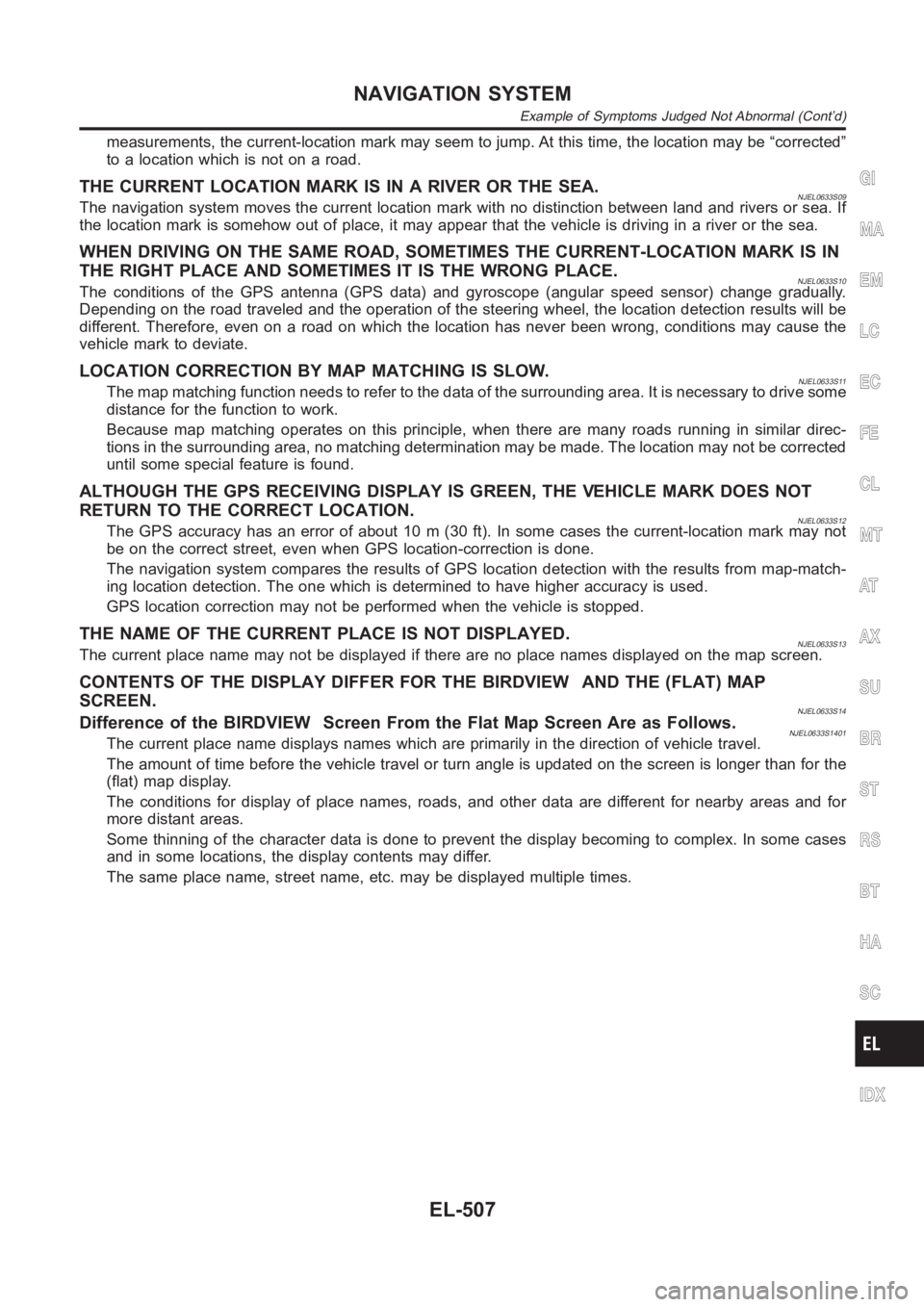
SKIA1621E
SERVICENJEL0604S08To set Service schedule, change Journey distance with joy-
stick. At the same time, the marker of journey distance will be
moved.
SKIA1622E
To reset to initial distance, select “Reset” and push “ENTER”.
When the indicator of “Service Information Display” is set
green, the color of the journey distance marker will be red. And
automatically Service information screen will be displayed
when journey distance is reached on service schedule.
NAVIGATION SYSTEM
Confirmation/Adjustment Mode (Cont’d)
EL-466
Page 2843 of 3189
measurements, the current-location mark may seem to jump. At this time, the location may be “corrected”
to a location which is not on a road.
THE CURRENT LOCATION MARK IS IN A RIVER OR THE SEA.NJEL0633S09The navigation system moves the current location mark with no distinctionbetween land and rivers or sea. If
the location mark is somehow out of place, it may appear that the vehicle is driving in a river or the sea.
WHEN DRIVING ON THE SAME ROAD, SOMETIMES THE CURRENT-LOCATION MARK IS IN
THE RIGHT PLACE AND SOMETIMES IT IS THE WRONG PLACE.
NJEL0633S10The conditions of the GPS antenna (GPS data) and gyroscope (angular speed sensor) change gradually.
Depending on the road traveled and the operation of the steering wheel, thelocation detection results will be
different. Therefore, even on a road on which the location has never been wrong, conditions may cause the
vehicle mark to deviate.
LOCATION CORRECTION BY MAP MATCHING IS SLOW.NJEL0633S11The map matching function needs to refer to the data of the surrounding area. It is necessary to drive some
distance for the function to work.
Because map matching operates on this principle, when there are many roadsrunning in similar direc-
tions in the surrounding area, no matching determination may be made. The location may not be corrected
until some special feature is found.
ALTHOUGH THE GPS RECEIVING DISPLAY IS GREEN, THE VEHICLE MARK DOES NOT
RETURN TO THE CORRECT LOCATION.
NJEL0633S12The GPS accuracy has an error of about 10 m (30 ft). In some cases the current-location mark may not
be on the correct street, even when GPS location-correction is done.
The navigation system compares the results of GPS location detection withthe results from map-match-
ing location detection. The one which is determined to have higher accuracyisused.
GPS location correction may not be performed when the vehicle is stopped.
THE NAME OF THE CURRENT PLACE IS NOT DISPLAYED.NJEL0633S13The current place name may not be displayed if there are no place names displayed on the map screen.
CONTENTS OF THE DISPLAY DIFFER FOR THE BIRDVIEW AND THE (FLAT) MAP
SCREEN.
NJEL0633S14Difference of the BIRDVIEW Screen From the Flat Map Screen Are as Follows.NJEL0633S1401The current place name displays names which are primarily in the directionof vehicle travel.
The amount of time before the vehicle travel or turn angle is updated on the screen is longer than for the
(flat) map display.
The conditions for display of place names, roads, and other data are different for nearby areas and for
more distant areas.
Some thinning of the character data is done to prevent the display becomingto complex. In some cases
and in some locations, the display contents may differ.
The same place name, street name, etc. may be displayed multiple times.
GI
MA
EM
LC
EC
FE
CL
MT
AT
AX
SU
BR
ST
RS
BT
HA
SC
IDX
NAVIGATION SYSTEM
Example of Symptoms Judged Not Abnormal (Cont’d)
EL-507
Page 2943 of 3189
RHA273D
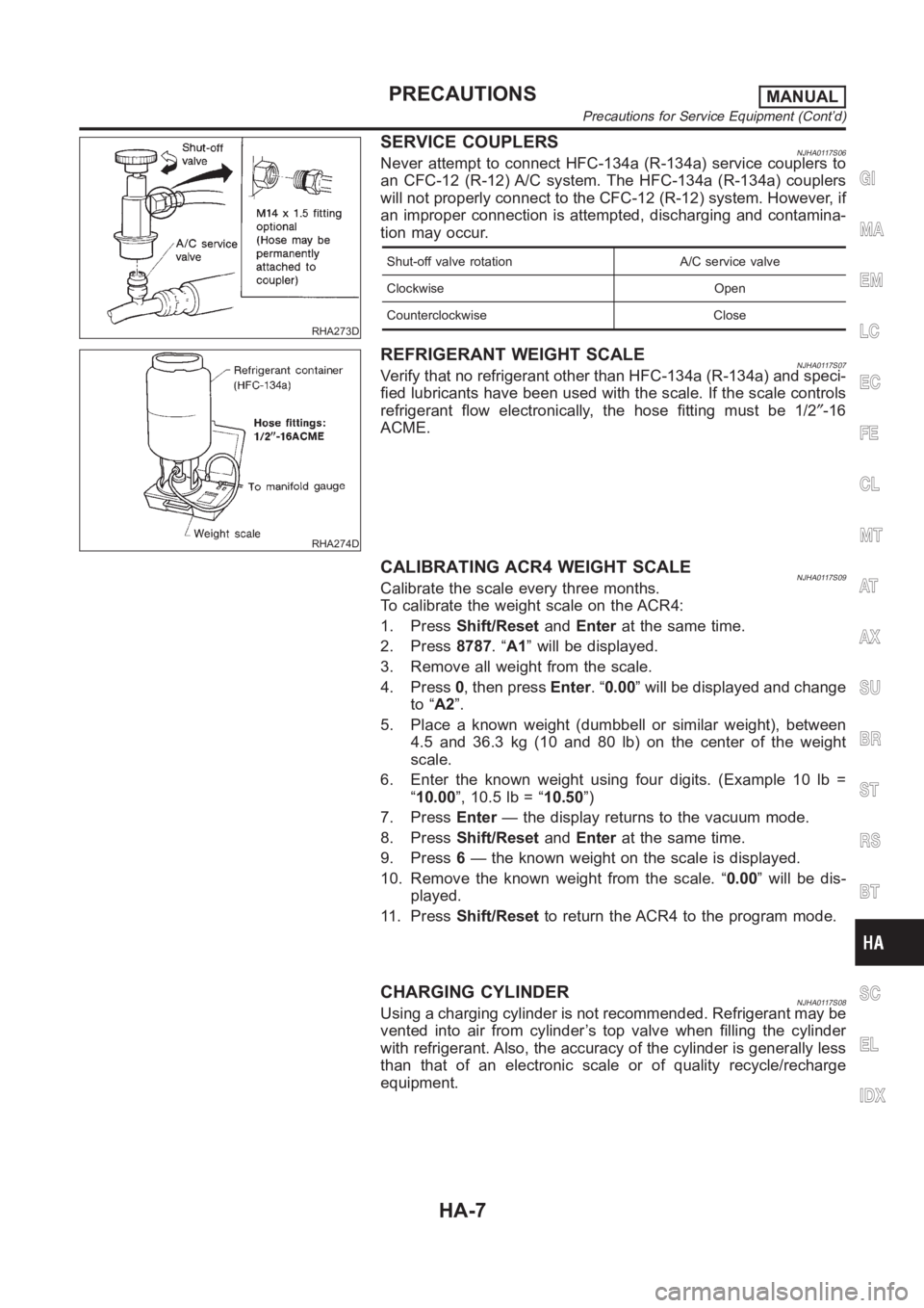
SERVICE COUPLERSNJHA0117S06Never attempt to connect HFC-134a (R-134a) service couplers to
an CFC-12 (R-12) A/C system. The HFC-134a (R-134a) couplers
will not properly connect to the CFC-12 (R-12) system. However, if
an improper connection is attempted, discharging and contamina-
tion may occur.
Shut-off valve rotation A/C service valve
Clockwise Open
Counterclockwise Close
RHA274D
REFRIGERANT WEIGHT SCALENJHA0117S07Verify that no refrigerant other than HFC-134a (R-134a) and speci-
fied lubricants have been used with the scale. If the scale controls
refrigerant flow electronically, the hose fitting must be 1/2″-16
ACME.
CALIBRATING ACR4 WEIGHT SCALENJHA0117S09Calibrate the scale every three months.
To calibrate the weight scale on the ACR4:
1. PressShift/ResetandEnterat the same time.
2. Press8787.“A1” will be displayed.
3. Remove all weight from the scale.
4. Press0, then pressEnter.“0.00” will be displayed and change
to “A2”.
5. Place a known weight (dumbbell or similar weight), between
4.5 and 36.3 kg (10 and 80 lb) on the center of the weight
scale.
6. Enter the known weight using four digits. (Example 10 lb =
“10.00”, 10.5 lb = “10.50”)
7. PressEnter— the display returns to the vacuum mode.
8. PressShift/ResetandEnterat the same time.
9. Press6— the known weight on the scale is displayed.
10. Remove the known weight from the scale. “0.00” will be dis-
played.
11. PressShift/Resetto return the ACR4 to the program mode.
CHARGING CYLINDERNJHA0117S08Using a charging cylinder is not recommended. Refrigerant may be
vented into air from cylinder’s top valve when filling the cylinder
with refrigerant. Also, the accuracy of the cylinder is generally less
than that of an electronic scale or of quality recycle/recharge
equipment.
GI
MA
EM
LC
EC
FE
CL
MT
AT
AX
SU
BR
ST
RS
BT
SC
EL
IDX
PRECAUTIONSMANUAL
Precautions for Service Equipment (Cont’d)
HA-7