2003 NISSAN ALMERA N16 door lock
[x] Cancel search: door lockPage 2478 of 3189
![NISSAN ALMERA N16 2003 Electronic Repair Manual 4. Select the desired part to be diagnosed on the “SELECT TES-
T ITEM” screen.
Data monitor item (KEY REMINDER)
Monitored item Description
IGNITION SW Indicates [ON/OFF] condition of ignition swit NISSAN ALMERA N16 2003 Electronic Repair Manual 4. Select the desired part to be diagnosed on the “SELECT TES-
T ITEM” screen.
Data monitor item (KEY REMINDER)
Monitored item Description
IGNITION SW Indicates [ON/OFF] condition of ignition swit](/manual-img/5/57350/w960_57350-2477.png)
4. Select the desired part to be diagnosed on the “SELECT TES-
T ITEM” screen.
Data monitor item (KEY REMINDER)
Monitored item Description
IGNITION SW Indicates [ON/OFF] condition of ignition switch.
KEY IN DETECT Indicates [ON/OFF] condition of electronic key switch.
DR DOOR SW Indicates [ON/OFF] condition of front door switch (driver side).
CDL LOCK SW Indicates [ON/OFF] condition of door lock/unlock switch.
RKE LOCK Indicates [ON/OFF] condition of lock signal from remote controller.
Data monitor item (Light warning chime)
Monitored item Description
IGN ON SW Indicates [ON/OFF] condition of ignition switch.
DR DOOR SW Indicates [ON/OFF] condition of front door switch (driver side).
TAIL LAMP ON Indicates [ON/OFF] condition of lighting switch.
SYMPTOM CHARTNJEL0551S02First perform the “SELF-DIAG RESULTS” in “SMART ENTRANCE”
with CONSULT-II, when perform the each trouble diagnosis.
Symptom Diagnoses/Service procedure Reference page
Light warning chime does not activate.Power supply and ground circuit checkEL-143, “Power Supply
and Ground Circuit
Check”
Lighting switch checkEL-144, “Lighting Switch
Input Signal Check”
Front door switch (driver side) checkEL-150, “Front Door
Switch (Driver side)
Check”
Key warning chime does not activate.Power supply and ground circuit checkEL-143, “Power Supply
and Ground Circuit
Check”
Key switch insert signal checkEL-147, “Key Switch
Insert Signal Check”
Front door switch (driver side) checkEL-150, “Front Door
Switch (Driver side)
Check”
All warning chimes do not activate. Power supply and ground circuit checkEL-143, “Power Supply
and Ground Circuit
Check”
With the ignition switch turned OFF and the
door closed (driver side) turning the lighting
switch ON (1st) activates the chime.Front door switch (driver side) checkEL-150, “Front Door
Switch (Driver side)
Check”
WARNING CHIME
Trouble Diagnoses/QG and YD Engine Models with Common Rail (Cont’d)
EL-142
Page 2488 of 3189
Trouble Diagnoses/YD Engine Models without
Common Rail and K9K Engine Models
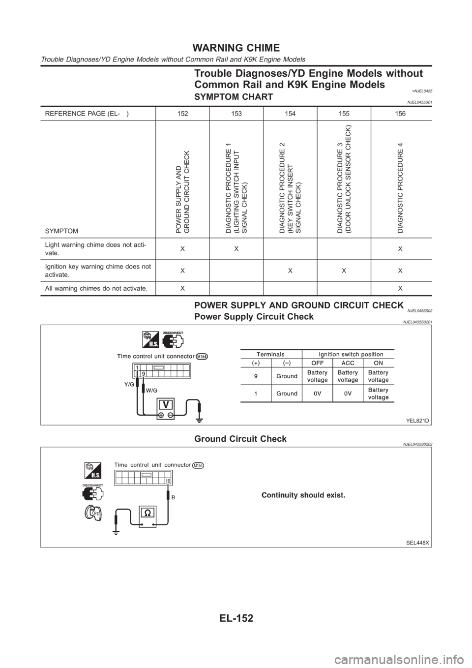
=NJEL0455SYMPTOM CHARTNJEL0455S01
REFERENCE PAGE (EL- ) 152 153 154 155 156
SYMPTOM
POWER SUPPLY AND
GROUND CIRCUIT CHECK
DIAGNOSTIC PROCEDURE 1
(LIGHTING SWITCH INPUT
SIGNAL CHECK)
DIAGNOSTIC PROCEDURE 2
(KEY SWITCH INSERT
SIGNAL CHECK)
DIAGNOSTIC PROCEDURE 3
(DOOR UNLOCK SENSOR CHECK)
DIAGNOSTIC PROCEDURE 4
Light warning chime does not acti-
vate.XX X
Ignition key warning chime does not
activate.XXXX
All warning chimes do not activate. XX
POWER SUPPLY AND GROUND CIRCUIT CHECKNJEL0455S02Power Supply Circuit CheckNJEL0455S0201
YEL821D
Ground Circuit CheckNJEL0455S0202
SEL448X
WARNING CHIME
Trouble Diagnoses/YD Engine Models without Common Rail and K9K Engine Models
EL-152
Page 2491 of 3189
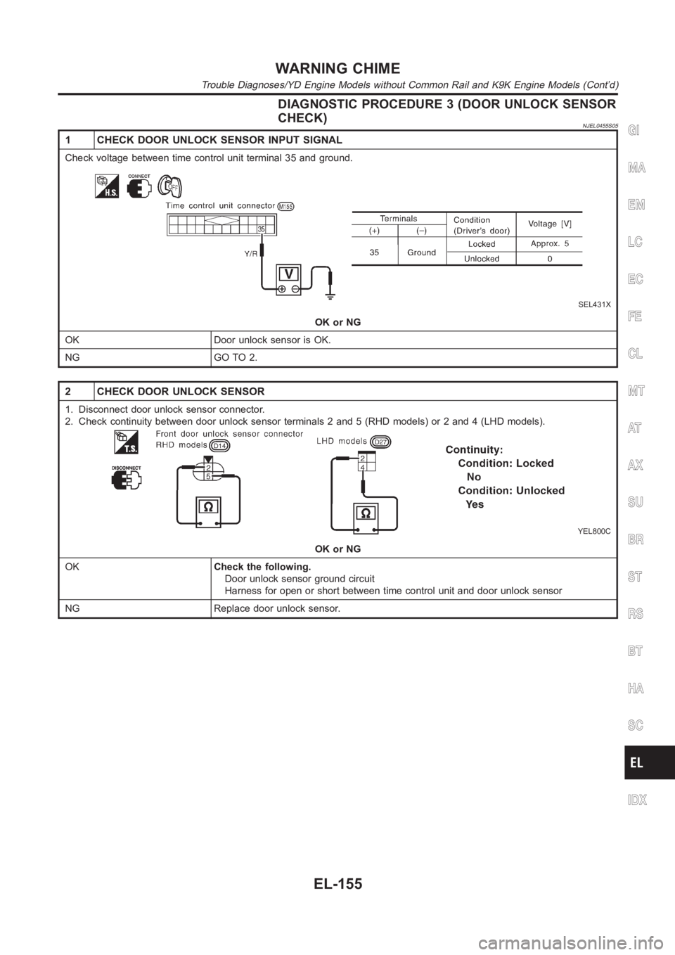
DIAGNOSTIC PROCEDURE 3 (DOOR UNLOCK SENSOR
CHECK)
NJEL0455S05
1 CHECK DOOR UNLOCK SENSOR INPUT SIGNAL
Check voltage between time control unit terminal 35 and ground.
SEL431X
OK or NG
OK Door unlock sensor is OK.
NG GO TO 2.
2 CHECK DOOR UNLOCK SENSOR
1. Disconnect door unlock sensor connector.
2. Check continuity between door unlock sensor terminals 2 and 5 (RHD models) or 2 and 4 (LHD models).
YEL800C
OK or NG
OKCheck the following.
Door unlock sensor ground circuit
Harness for open or short between time control unit and door unlock sensor
NG Replace door unlock sensor.
GI
MA
EM
LC
EC
FE
CL
MT
AT
AX
SU
BR
ST
RS
BT
HA
SC
IDX
WARNING CHIME
Trouble Diagnoses/YD Engine Models without Common Rail and K9K Engine Models (Cont’d)
EL-155
Page 2492 of 3189
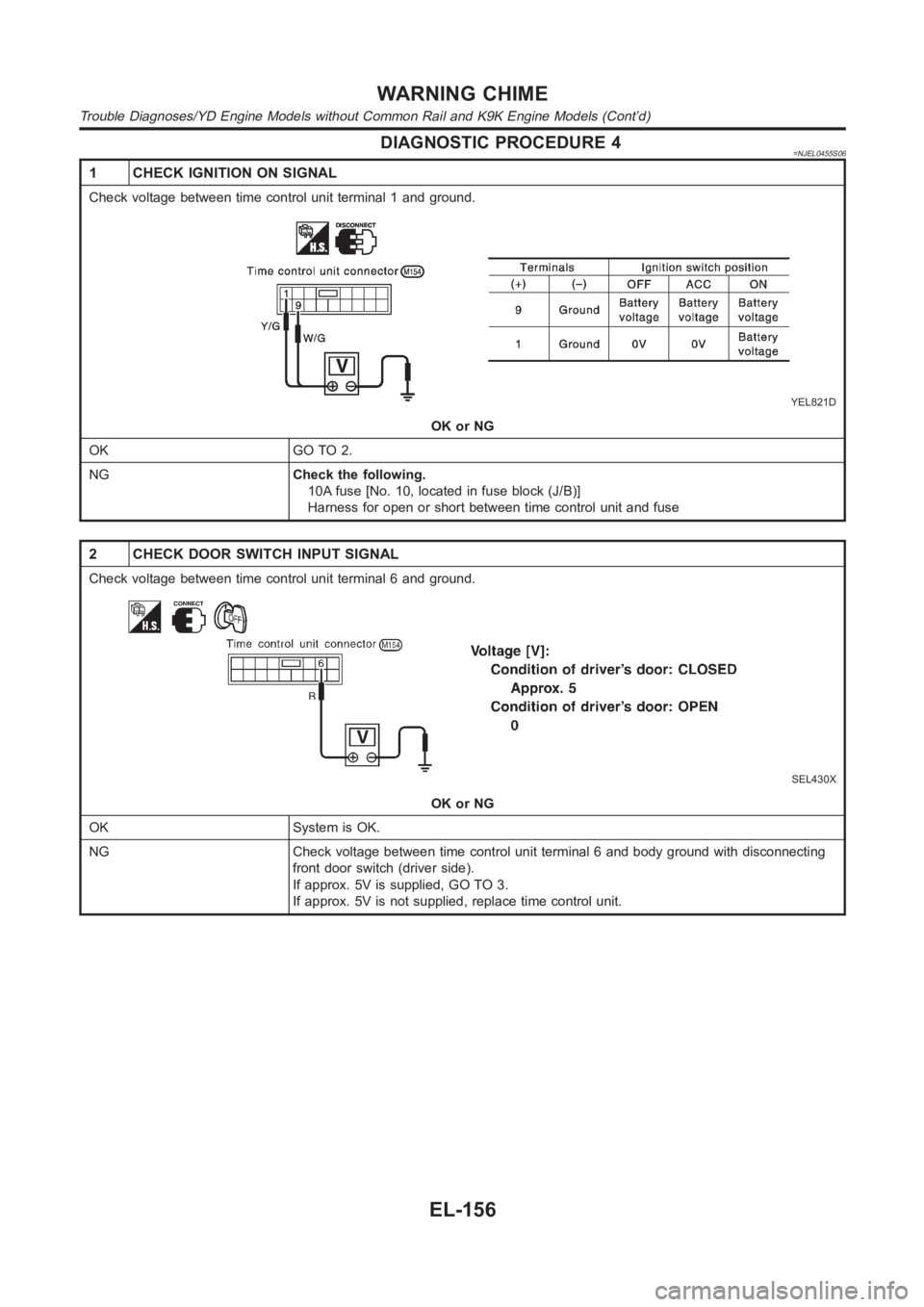
DIAGNOSTIC PROCEDURE 4=NJEL0455S06
1 CHECK IGNITION ON SIGNAL
Check voltage between time control unit terminal 1 and ground.
YEL821D
OK or NG
OK GO TO 2.
NGCheck the following.
10A fuse [No. 10, located in fuse block (J/B)]
Harness for open or short between time control unit and fuse
2 CHECK DOOR SWITCH INPUT SIGNAL
Check voltage between time control unit terminal 6 and ground.
SEL430X
OK or NG
OK System is OK.
NG Check voltage between time control unit terminal 6 and body ground with disconnecting
front door switch (driver side).
If approx. 5V is supplied, GO TO 3.
If approx. 5V is not supplied, replace time control unit.
WARNING CHIME
Trouble Diagnoses/YD Engine Models without Common Rail and K9K Engine Models (Cont’d)
EL-156
Page 2509 of 3189
System Description/QG and YD Engine Models
with Common Rail
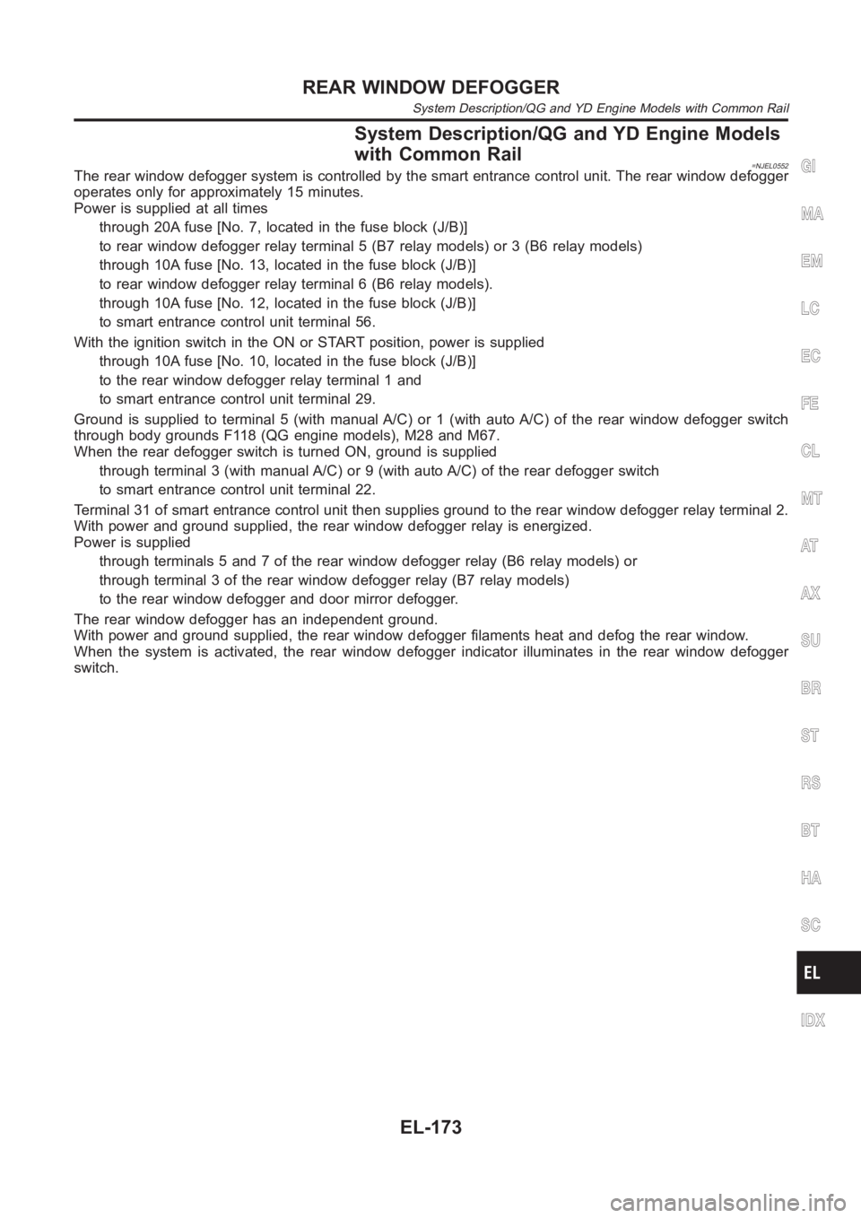
=NJEL0552The rear window defogger system is controlled by the smart entrance control unit. The rear window defogger
operates only for approximately 15 minutes.
Power is supplied at all times
through 20A fuse [No. 7, located in the fuse block (J/B)]
to rear window defogger relay terminal 5 (B7 relay models) or 3 (B6 relay models)
through 10A fuse [No. 13, located in the fuse block (J/B)]
to rear window defogger relay terminal 6 (B6 relay models).
through 10A fuse [No. 12, located in the fuse block (J/B)]
to smart entrance control unit terminal 56.
With the ignition switch in the ON or START position, power is supplied
through 10A fuse [No. 10, located in the fuse block (J/B)]
to the rear window defogger relay terminal 1 and
to smart entrance control unit terminal 29.
Ground is supplied to terminal 5 (with manual A/C) or 1 (with auto A/C) of therear window defogger switch
through body grounds F118 (QG engine models), M28 and M67.
When the rear defogger switch is turned ON, ground is supplied
through terminal 3 (with manual A/C) or 9 (with auto A/C) of the rear defogger switch
to smart entrance control unit terminal 22.
Terminal 31 of smart entrance control unit then supplies ground to the rearwindow defogger relay terminal 2.
With power and ground supplied, the rear window defogger relay is energized.
Power is supplied
through terminals 5 and 7 of the rear window defogger relay (B6 relay models)or
through terminal 3 of the rear window defogger relay (B7 relay models)
to the rear window defogger and door mirror defogger.
The rear window defogger has an independent ground.
With power and ground supplied, the rear window defogger filaments heat and defog the rear window.
When the system is activated, the rear window defogger indicator illuminates in the rear window defogger
switch.GI
MA
EM
LC
EC
FE
CL
MT
AT
AX
SU
BR
ST
RS
BT
HA
SC
IDX
REAR WINDOW DEFOGGER
System Description/QG and YD Engine Models with Common Rail
EL-173
Page 2510 of 3189
System Description/YD Engine Models without
Common Rail and K9K Engine Models
=NJEL0463The rear window defogger system is controlled by the time control unit. Therear window defogger operates
only for approximately 15 minutes.
Power is supplied at all times
through 20A fuse [No. 7, located in the fuse block (J/B)]
to rear window defogger relay terminal 5 (B7 relay models) or 3 (B6 relay models)
through 10A fuse [No. 13, located in the fuse block (J/B)]
to rear window defogger relay terminal 6 (B6 relay models).
through 15A fuse [No. 5, located in the fuse block (J/B)]
to time control unit terminal 9.
With the ignition switch in the ON or START position, power is supplied
through 10A fuse [No. 10, located in the fuse block (J/B)]
to the rear window defogger relay terminal 1 and
to time control unit terminal 1.
Ground is supplied to terminal 5 of the rear window defogger switch throughbody grounds M28 and M67.
When the rear defogger switch is turned ON, ground is supplied
through terminal 3 of the rear defogger switch
to time control unit terminal 3.
Terminal 13 of time control unit then supplies ground to the rear window defogger relay terminal 2.
With power and ground supplied, the rear window defogger relay is energized.
Power is supplied
through terminals 5 and 7 of the rear window defogger relay (B6 relay models)or
through terminal 3 of the rear window defogger relay (B7 relay models)
to the rear window defogger and door mirror defogger.
The rear window defogger has an independent ground.
With power and ground supplied, the rear window defogger filaments heat and defog the rear window.
When the system is activated, the rear window defogger indicator illuminates in the rear window defogger
switch.
REAR WINDOW DEFOGGER
System Description/YD Engine Models without Common Rail and K9K Engine Models
EL-174
Page 2528 of 3189
System Description=NJEL0497AUDIO SYSTEM WITHOUT DISPLAYNJEL0497S08Refer to Owner’s Manual for audio system operating instructions.
Power is supplied at all times
through 15A fuse (No. 40, located in the fusible link and fuse block)
to audio unit terminal 9.
With the ignition switch in the ACC or ON position, power is supplied
through 10A fuse [No. 1, located in the fuse block (J/B)]
to audio unit terminal 3.
Ground is supplied through the case of the audio unit.
Audio signals are supplied
through audio unit terminals 7, 10, 11, 12, 13, 14, 15, 16
to terminals 1 and 2 of front door speaker LH and RH,
to terminals 1 and 2 of rear door speaker LH and RH and
to terminals 1 and 2 of pillar tweeter LH and RH (with 6 speakers)
AUDIO SYSTEM WITH DISPLAYNJEL0497S09Refer to Owner’s Manual for audio system operating instructions.
Power is supplied at all times
through 15A fuse (No. 40, located in the fuse and fusible link box)
to audio unit terminals 3 and 4, and
to display terminals 21 and 23.
With the ignition switch in the ACC or ON position, power is supplied
through 10A fuse [No. 1, located in the fuse block (J/B)]
to audio unit terminal 2,
to multifunction switch terminal 6 and
to display terminal 19.
Ground is supplied through the case of the audio unit.
Ground is also supplied
through body grounds M28, M67 and F118 (QG engine models)
to multifunction switch terminal 1 and
to display terminals 22 and 24.
Audio signals are supplied
through audio unit terminals 5, 6, 7, 8, 9, 10, 11, 12
to terminals 1 and 2 of front door speaker LH and RH
to terminals 1 and 2 of rear door speaker LH and RH
to terminals 1 and 2 of tweeter LH and RH
AV COMMUNICATION LINENJEL0497S10Audio system is contained and the AV communication line is connected as followings.
Display unit terminals 12 and 13, and
Multifunction switch terminals 12 and 14.
Multifunction switch terminals 11 and 13, and
Audio unit terminals 31 and 32.
Audio unit terminals 35 and 36, and
AV and NAVI control unit terminals 47 and 48 (with navigation system).
The operation is controlled by operation signals from multifunction switch, then audio screen is displayed.
NAVIGATION SYSTEM OF GUIDANCE VOICE OPERATIONNJEL0497S11When navigation system is used, guidance voice signal is supplied
from AV and NAVI control unit terminals 7 and 8
to audio unit terminals 35 and 36.
Navigation system of guidance voice will be sounded.
AUDIO
System Description
EL-192
Page 2578 of 3189
![NISSAN ALMERA N16 2003 Electronic Repair Manual Warning indicatorsWarning lamps in
instrument panelWarning detection and cancel conditions Cases of malfunction
DOOR OPEN DoorDetection conditionVehicle is running [approx. 5
km/h (3 MPH) or faster] a NISSAN ALMERA N16 2003 Electronic Repair Manual Warning indicatorsWarning lamps in
instrument panelWarning detection and cancel conditions Cases of malfunction
DOOR OPEN DoorDetection conditionVehicle is running [approx. 5
km/h (3 MPH) or faster] a](/manual-img/5/57350/w960_57350-2577.png)
Warning indicatorsWarning lamps in
instrument panelWarning detection and cancel conditions Cases of malfunction
DOOR OPEN DoorDetection conditionVehicle is running [approx. 5
km/h (3 MPH) or faster] and door
ajar of any of the doors is
detected.Doorisopen
Cancel conditionVehicle is stopped and all the
doors lock.
ABS ABSDetection conditionWarning lamp ON signal is
detected when engine is running.
ABS control system mal-
function
Cancel conditionWarning lamp OFF signal is
detected.
ESP ELECTRONIC
CONTROL SYSTEMESPDetection conditionWarning lamp ON signal is
detected when engine is running.
ESP system malfunction
Cancel conditionWarning lamp OFF signal is
detected.
CVT ELECTRONIC
CONTROL SYSTEMCVTDetection conditionWarning lamp ON signal is
detected after ignition switch is
turned ON.
TCM system malfunction
Cancel conditionWarning lamp OFF signal is
detected.
CRUISE CONTROL
SYSTEMCRUISEDetection conditionWarning lamp ON signal is
detected after ignition switch is
turned ON.
ICC system malfunction
Cancel conditionWarning lamp OFF signal is
detected.
Precautions for Display Unit ReplacementNJEL0572Record the following memorized contents before replacing the control unit.
Preset frequency
Area for indicating station, selection of overlapped stations
Program status
Volume balance memory set values
Equalizer memory set values
Brightness of light when ON/OFF
Dimming switching
Display color switching
Replace the display unit after disconnecting both battery cables.
Component Parts and Harness Connector and
Harness Connector Location
NJEL0573For details, refer to “ELECTRICAL UNIT LOCATION” (EL-543) and “HARNESS LAYOUT” (EL-550).
LCD DISPLAY
System Description (Cont’d)
EL-242