Page 2416 of 3189
![NISSAN ALMERA N16 2003 Electronic Repair Manual System Description/QG and YD Engine Models
with Common Rail
=NJEL0435POWER SUPPLY AND GROUNDNJEL0435S01Power is supplied at all times:
through 10A fuse [No. 12, located in the fuse block (J/B)]
to sma NISSAN ALMERA N16 2003 Electronic Repair Manual System Description/QG and YD Engine Models
with Common Rail
=NJEL0435POWER SUPPLY AND GROUNDNJEL0435S01Power is supplied at all times:
through 10A fuse [No. 12, located in the fuse block (J/B)]
to sma](/manual-img/5/57350/w960_57350-2415.png)
System Description/QG and YD Engine Models
with Common Rail
=NJEL0435POWER SUPPLY AND GROUNDNJEL0435S01Power is supplied at all times:
through 10A fuse [No. 12, located in the fuse block (J/B)]
to smart entrance control unit terminal 56
to key switch terminal 1 and
through 10A fuse [No. 13, located in the fuse block (J/B)]
to interior room lamp terminal 1.
When the key is removed from ignition key cylinder, power is interrupted:
through key switch terminal 2
to smart entrance control unit terminal 5.
With the ignition key switch in the ON or START position, power is supplied:
through 10A fuse [No. 10, located in the fuse block (J/B)]
to smart entrance control unit terminal 29.
Ground is supplied:
through body grounds terminals F118 (QG engine models), M28 and M67
to smart entrance control unit terminal 53
When the driver side door is opened, ground is supplied:
through body grounds B9, B21 and D96 (Hatchback) or B308 (Sedan)
to door switch driver side terminal 3
from door switch driver side terminal 2
to smart entrance control unit terminal 43.
When any door is opened, ground is supplied:
through case ground of each door switch
to each door switch terminal 1
to smart entrance control unit terminal 44.
When the driver side door is unlocked by the door lock/unlock switch, the smart entrance control unit receives
a ground signal:
through body grounds M28, M67 and F118 (QG engine models)
to door lock/unlock switch terminal 3
from door lock/unlock switch terminal 7 (with power window system) or
from door lock/unlock switch terminal 2 (without power window system)
to smart entrance control unit terminal 14.
When the driver side door is locked by the door lock/unlock switch, the smart entrance control unit receives
a ground signal:
through body grounds M28, M67 and F118 (QG engine models)
to door lock/unlock switch terminal 3
from door lock/unlock switch terminal 14 (with power window system) or
from door lock/unlock switch terminal 1 (without power window system)
to smart entrance control unit terminal 13.
When a signal, or combination of signals is received by the smart entrance control unit, ground is supplied:
through smart entrance control unit terminal 28
to interior room lamp terminal 5.
With power and ground supplied, the interior room lamp illuminates when interior room lamp switch is in
“DOOR” position.
SWITCH OPERATIONNJEL0435S02When interior room lamp switch is in “ON” position, ground is supplied:
through case grounds of interior room lamp
to interior room lamp.
With power and ground supplied, the interior room lamp illuminates.
INTERIOR ROOM LAMP
System Description/QG and YD Engine Models with Common Rail
EL-80
Page 2417 of 3189

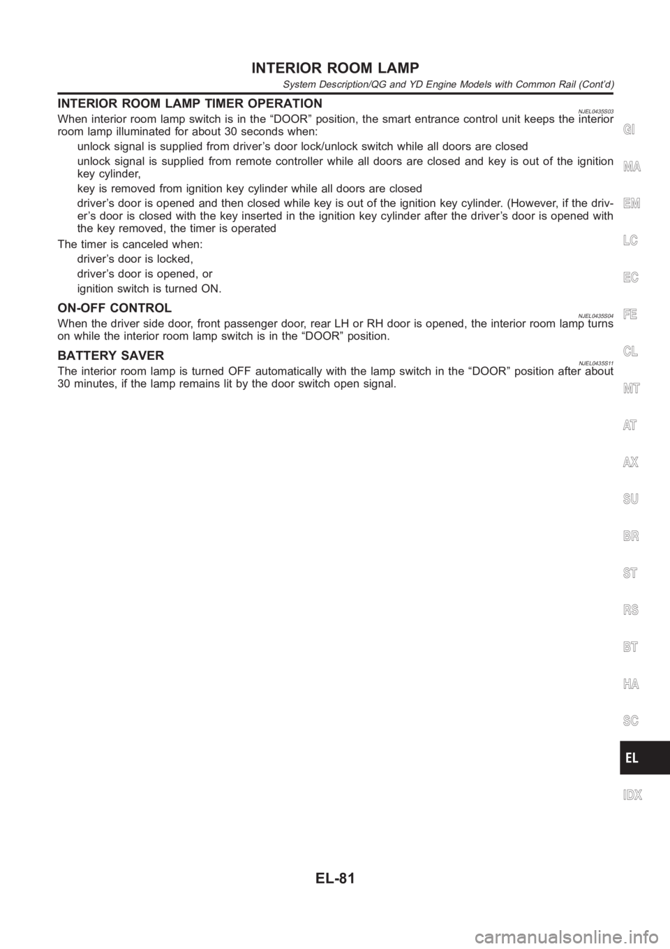
INTERIOR ROOM LAMP TIMER OPERATIONNJEL0435S03When interior room lamp switch is in the “DOOR” position, the smart entrance control unit keeps the interior
room lamp illuminated for about 30 seconds when:
unlock signal is supplied from driver’s door lock/unlock switch while alldoors are closed
unlock signal is supplied from remote controller while all doors are closed and key is out of the ignition
key cylinder,
key is removed from ignition key cylinder while all doors are closed
driver’s door is opened and then closed while key is out of the ignition key cylinder. (However, if the driv-
er’s door is closed with the key inserted in the ignition key cylinder afterthe driver’s door is opened with
the key removed, the timer is operated
The timer is canceled when:
driver’s door is locked,
driver’s door is opened, or
ignition switch is turned ON.
ON-OFF CONTROLNJEL0435S04When the driver side door, front passenger door, rear LH or RH door is opened, the interior room lamp turns
on while the interior room lamp switch is in the “DOOR” position.
BATTERY SAVERNJEL0435S11The interior room lamp is turned OFF automatically with the lamp switch in the “DOOR” position after about
30 minutes, if the lamp remains lit by the door switch open signal.
GI
MA
EM
LC
EC
FE
CL
MT
AT
AX
SU
BR
ST
RS
BT
HA
SC
IDX
INTERIOR ROOM LAMP
System Description/QG and YD Engine Models with Common Rail (Cont’d)
EL-81
Page 2418 of 3189

System Description/YD Engine Models without
Common Rail and K9K Engine Models
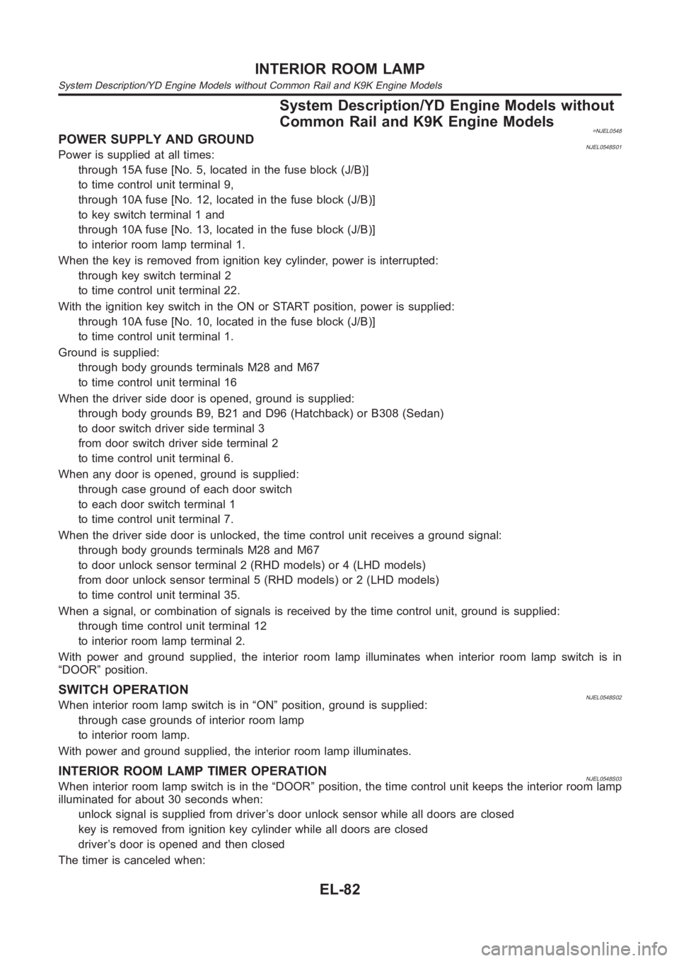
=NJEL0548POWER SUPPLY AND GROUNDNJEL0548S01Power is supplied at all times:
through 15A fuse [No. 5, located in the fuse block (J/B)]
to time control unit terminal 9,
through 10A fuse [No. 12, located in the fuse block (J/B)]
to key switch terminal 1 and
through 10A fuse [No. 13, located in the fuse block (J/B)]
to interior room lamp terminal 1.
When the key is removed from ignition key cylinder, power is interrupted:
through key switch terminal 2
to time control unit terminal 22.
With the ignition key switch in the ON or START position, power is supplied:
through 10A fuse [No. 10, located in the fuse block (J/B)]
to time control unit terminal 1.
Ground is supplied:
through body grounds terminals M28 and M67
to time control unit terminal 16
When the driver side door is opened, ground is supplied:
through body grounds B9, B21 and D96 (Hatchback) or B308 (Sedan)
to door switch driver side terminal 3
from door switch driver side terminal 2
to time control unit terminal 6.
When any door is opened, ground is supplied:
through case ground of each door switch
to each door switch terminal 1
to time control unit terminal 7.
When the driver side door is unlocked, the time control unit receives a ground signal:
through body grounds terminals M28 and M67
to door unlock sensor terminal 2 (RHD models) or 4 (LHD models)
from door unlock sensor terminal 5 (RHD models) or 2 (LHD models)
to time control unit terminal 35.
When a signal, or combination of signals is received by the time control unit, ground is supplied:
through time control unit terminal 12
to interior room lamp terminal 2.
With power and ground supplied, the interior room lamp illuminates when interior room lamp switch is in
“DOOR” position.
SWITCH OPERATIONNJEL0548S02When interior room lamp switch is in “ON” position, ground is supplied:
through case grounds of interior room lamp
to interior room lamp.
With power and ground supplied, the interior room lamp illuminates.
INTERIOR ROOM LAMP TIMER OPERATIONNJEL0548S03When interior room lamp switch is in the “DOOR” position, the time control unit keeps the interior room lamp
illuminated for about 30 seconds when:
unlock signal is supplied from driver’s door unlock sensor while all doorsare closed
key is removed from ignition key cylinder while all doors are closed
driver’s door is opened and then closed
The timer is canceled when:
INTERIOR ROOM LAMP
System Description/YD Engine Models without Common Rail and K9K Engine Models
EL-82
Page 2419 of 3189
driver’s door is locked,
driver’s door is opened, or
ignition switch is turned ON.
ON-OFF CONTROLNJEL0548S04When the driver side door, front passenger door, rear LH or RH door is opened, the interior room lamp turns
on while the interior room lamp switch is in the “DOOR” position.
BATTERY SAVERNJEL0548S05The interior room lamp is turned OFF automatically with the lamp switch in the “DOOR” position after about
30 minutes, if the lamp remains lit by the door switch open signal.
GI
MA
EM
LC
EC
FE
CL
MT
AT
AX
SU
BR
ST
RS
BT
HA
SC
IDX
INTERIOR ROOM LAMP
System Description/YD Engine Models without Common Rail and K9K Engine Models (Cont’d)
EL-83
Page 2422 of 3189

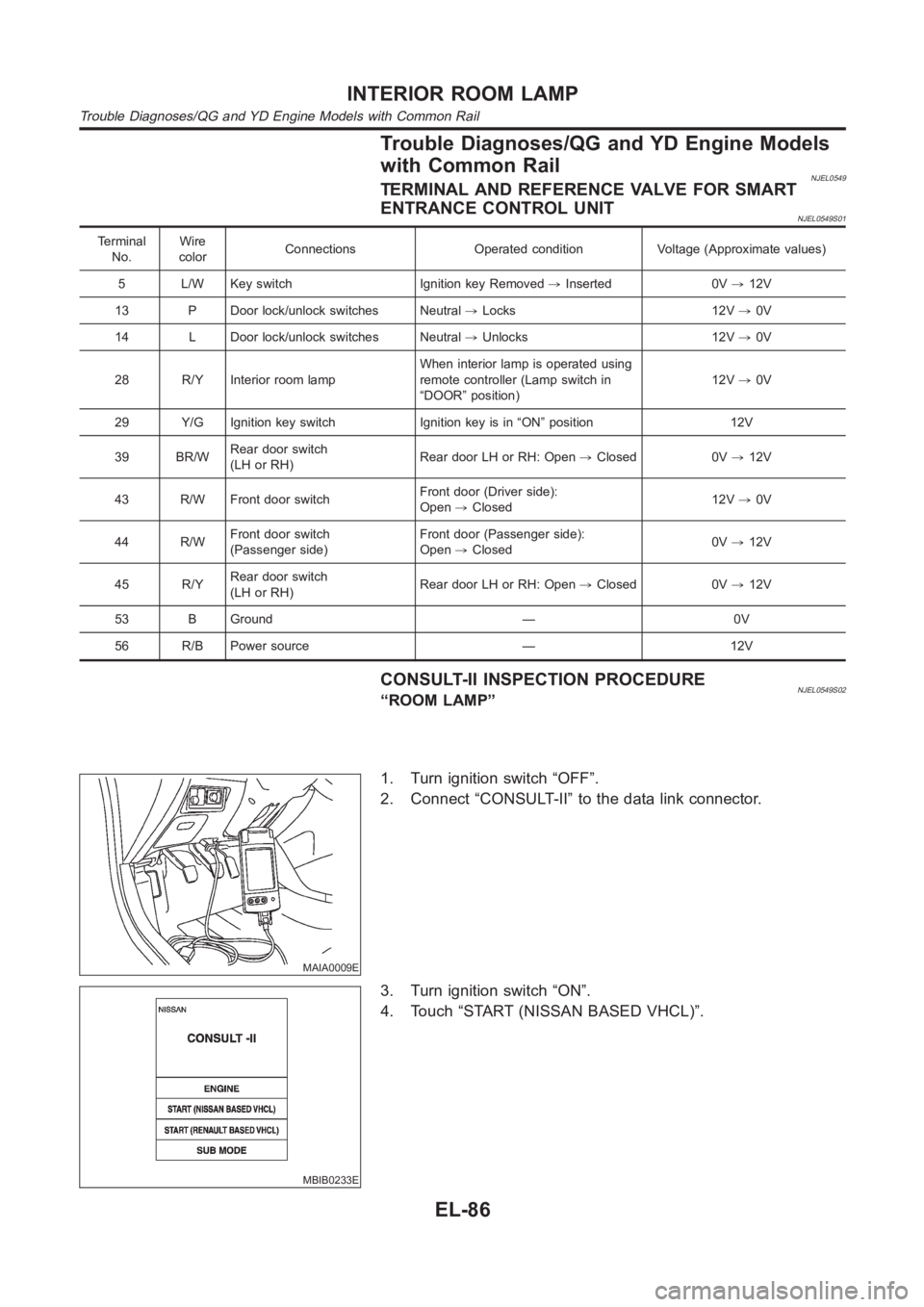
Trouble Diagnoses/QG and YD Engine Models
with Common Rail
NJEL0549TERMINAL AND REFERENCE VALVE FOR SMART
ENTRANCE CONTROL UNIT
NJEL0549S01
Terminal
No.Wire
colorConnections Operated condition Voltage (Approximate values)
5 L/W Key switch Ignition key Removed,Inserted 0V,12V
13 P Door lock/unlock switches Neutral,Locks 12V,0V
14 L Door lock/unlock switches Neutral,Unlocks 12V,0V
28 R/Y Interior room lampWhen interior lamp is operated using
remote controller (Lamp switch in
“DOOR” position)12V,0V
29 Y/G Ignition key switch Ignition key is in “ON” position 12V
39 BR/WRear door switch
(LH or RH)Rear door LH or RH: Open,Closed 0V,12V
43 R/W Front door switchFront door (Driver side):
Open,Closed12V,0V
44 R/WFront door switch
(Passenger side)Front door (Passenger side):
Open,Closed0V,12V
45 R/YRear door switch
(LH or RH)Rear door LH or RH: Open,Closed 0V,12V
53 B Ground — 0V
56 R/B Power source — 12V
CONSULT-II INSPECTION PROCEDURENJEL0549S02“ROOM LAMP”
MAIA0009E
1. Turn ignition switch “OFF”.
2. Connect “CONSULT-II” to the data link connector.
MBIB0233E
3. Turn ignition switch “ON”.
4. Touch “START (NISSAN BASED VHCL)”.
INTERIOR ROOM LAMP
Trouble Diagnoses/QG and YD Engine Models with Common Rail
EL-86
Page 2423 of 3189

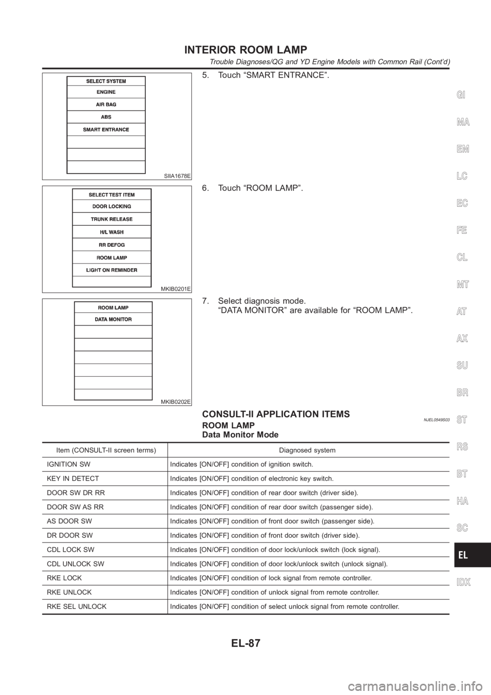
SIIA1678E
5. Touch “SMART ENTRANCE”.
MKIB0201E
6. Touch “ROOM LAMP”.
MKIB0202E
7. Select diagnosis mode.
“DATA MONITOR” are available for “ROOM LAMP”.
CONSULT-II APPLICATION ITEMSNJEL0549S03ROOM LAMP
Data Monitor Mode
Item (CONSULT-II screen terms) Diagnosed system
IGNITION SW Indicates [ON/OFF] condition of ignition switch.
KEY IN DETECT Indicates [ON/OFF] condition of electronic key switch.
DOOR SW DR RR Indicates [ON/OFF] condition of rear door switch (driver side).
DOOR SW AS RR Indicates [ON/OFF] condition of rear door switch (passenger side).
AS DOOR SW Indicates [ON/OFF] condition of front door switch (passenger side).
DR DOOR SW Indicates [ON/OFF] condition of front door switch (driver side).
CDL LOCK SW Indicates [ON/OFF] condition of door lock/unlock switch (locksignal).
CDL UNLOCK SW Indicates [ON/OFF] condition of door lock/unlock switch (unlock signal).
RKE LOCK Indicates [ON/OFF] condition of lock signal from remote controller.
RKE UNLOCK Indicates [ON/OFF] condition of unlock signal from remote controller.
RKE SEL UNLOCK Indicates [ON/OFF] condition of select unlock signal from remote controller.
GI
MA
EM
LC
EC
FE
CL
MT
AT
AX
SU
BR
ST
RS
BT
HA
SC
IDX
INTERIOR ROOM LAMP
Trouble Diagnoses/QG and YD Engine Models with Common Rail (Cont’d)
EL-87
Page 2427 of 3189
4 CHECK DOOR LOCK/UNLOCK SWITCH
WITH CONSULT-II
Check door lock/unlock switch signal (“CDL LOCK SW” or “CDL UNLOCK SW”) in “DATA MONITOR” mode with CON-
SULT-II.
MKIB0198E
When door lock/unlock is locked:
CDL LOCK SW ON
CDL UNLOCK SW OFF
When door lock/unlock is unlocked:
CDL LOCK SW OFF
CDL UNLOCK SW ON
WITHOUT CONSULT-II
Check voltage between smart entrance control unit harness connector M193terminals 13 (P), 14 (L) and ground.
SIIA1567E
MTBL1425
OK or NG
OK GO TO 6.
NG GO TO 5.
GI
MA
EM
LC
EC
FE
CL
MT
AT
AX
SU
BR
ST
RS
BT
HA
SC
IDX
INTERIOR ROOM LAMP
Trouble Diagnoses/QG and YD Engine Models with Common Rail (Cont’d)
EL-91
Page 2428 of 3189
5 CHECK DOOR LOCK/UNLOCK SWITCH
1. Disconnect door lock/unlock switch harness connector.
2. Check continuity between door lock/unlock switch harness connector terminals 2 and 3.
Power window main switch (door lock/unlock switch) (with power window system)
YEL803C
Door lock/unlock switch (without power window system)
SEL469X
OK or NG
OK Check harness for open or short between smart entrance control unit and door lock/
unlock switch.
NG Replace lock/unlock switch.
INTERIOR ROOM LAMP
Trouble Diagnoses/QG and YD Engine Models with Common Rail (Cont’d)
EL-92