2003 NISSAN ALMERA N16 audio
[x] Cancel search: audioPage 2821 of 3189
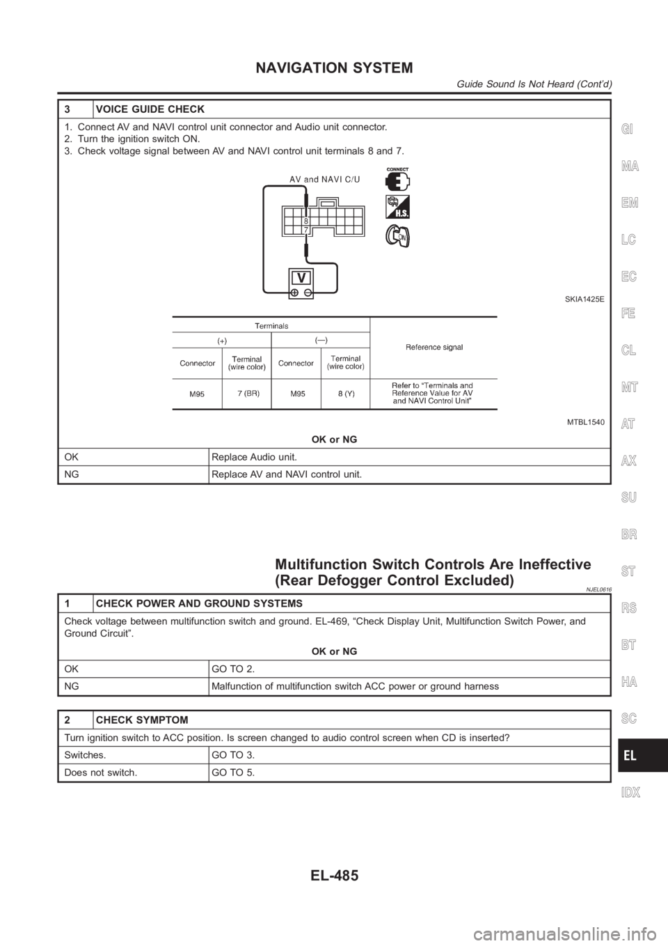
3 VOICE GUIDE CHECK
1. Connect AV and NAVI control unit connector and Audio unit connector.
2. Turn the ignition switch ON.
3. Check voltage signal between AV and NAVI control unit terminals 8 and 7.
SKIA1425E
MTBL1540
OK or NG
OK Replace Audio unit.
NG Replace AV and NAVI control unit.
Multifunction Switch Controls Are Ineffective
(Rear Defogger Control Excluded)
NJEL0616
1 CHECK POWER AND GROUND SYSTEMS
Check voltage between multifunction switch and ground. EL-469, “Check Display Unit, Multifunction Switch Power, and
Ground Circuit”.
OK or NG
OK GO TO 2.
NG Malfunction of multifunction switch ACC power or ground harness
2 CHECK SYMPTOM
Turn ignition switch to ACC position. Is screen changed to audio control screen when CD is inserted?
Switches. GO TO 3.
Does not switch. GO TO 5.
GI
MA
EM
LC
EC
FE
CL
MT
AT
AX
SU
BR
ST
RS
BT
HA
SC
IDX
NAVIGATION SYSTEM
Guide Sound Is Not Heard (Cont’d)
EL-485
Page 2822 of 3189
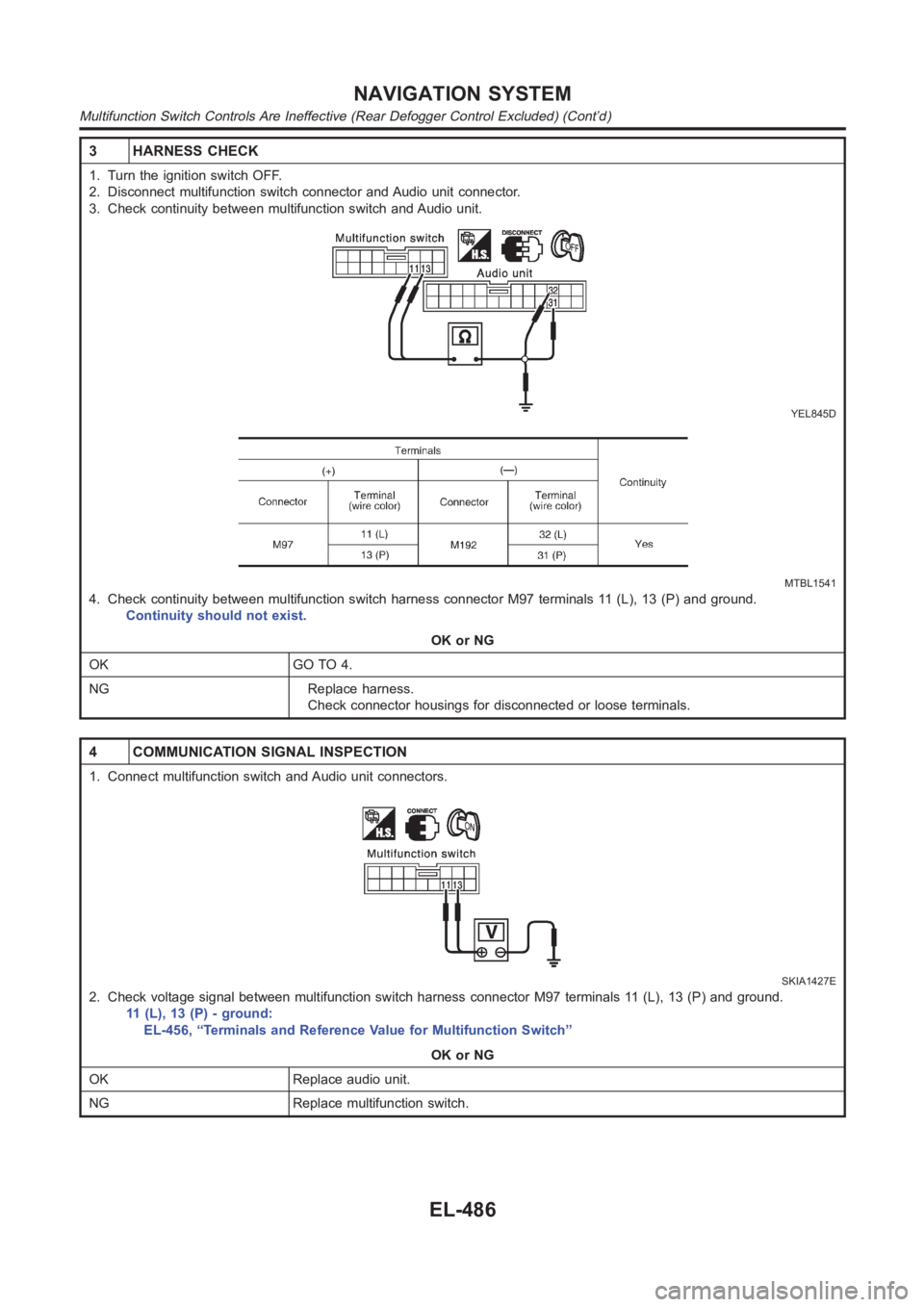
3 HARNESS CHECK
1. Turn the ignition switch OFF.
2. Disconnect multifunction switch connector and Audio unit connector.
3. Check continuity between multifunction switch and Audio unit.
YEL845D
MTBL1541
4. Check continuity between multifunction switch harness connector M97 terminals 11 (L), 13 (P) and ground.
Continuity should not exist.
OK or NG
OK GO TO 4.
NG Replace harness.
Check connector housings for disconnected or loose terminals.
4 COMMUNICATION SIGNAL INSPECTION
1. Connect multifunction switch and Audio unit connectors.
SKIA1427E
2. Check voltage signal between multifunction switch harness connector M97 terminals 11 (L), 13 (P) and ground.
11 (L), 13 (P) - ground:
EL-456, “Terminals and Reference Value for Multifunction Switch”
OK or NG
OK Replace audio unit.
NG Replace multifunction switch.
NAVIGATION SYSTEM
Multifunction Switch Controls Are Ineffective (Rear Defogger Control Excluded) (Cont’d)
EL-486
Page 2823 of 3189
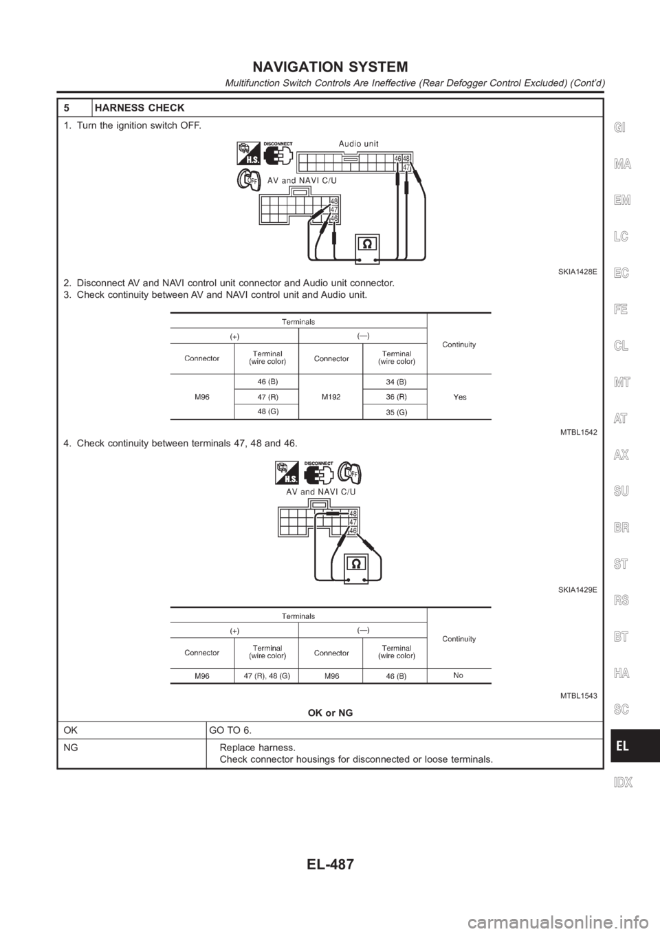
5 HARNESS CHECK
1. Turn the ignition switch OFF.
SKIA1428E
2. Disconnect AV and NAVI control unit connector and Audio unit connector.
3. Check continuity between AV and NAVI control unit and Audio unit.
MTBL1542
4. Check continuity between terminals 47, 48 and 46.
SKIA1429E
MTBL1543
OK or NG
OK GO TO 6.
NG Replace harness.
Check connector housings for disconnected or loose terminals.
GI
MA
EM
LC
EC
FE
CL
MT
AT
AX
SU
BR
ST
RS
BT
HA
SC
IDX
NAVIGATION SYSTEM
Multifunction Switch Controls Are Ineffective (Rear Defogger Control Excluded) (Cont’d)
EL-487
Page 2824 of 3189
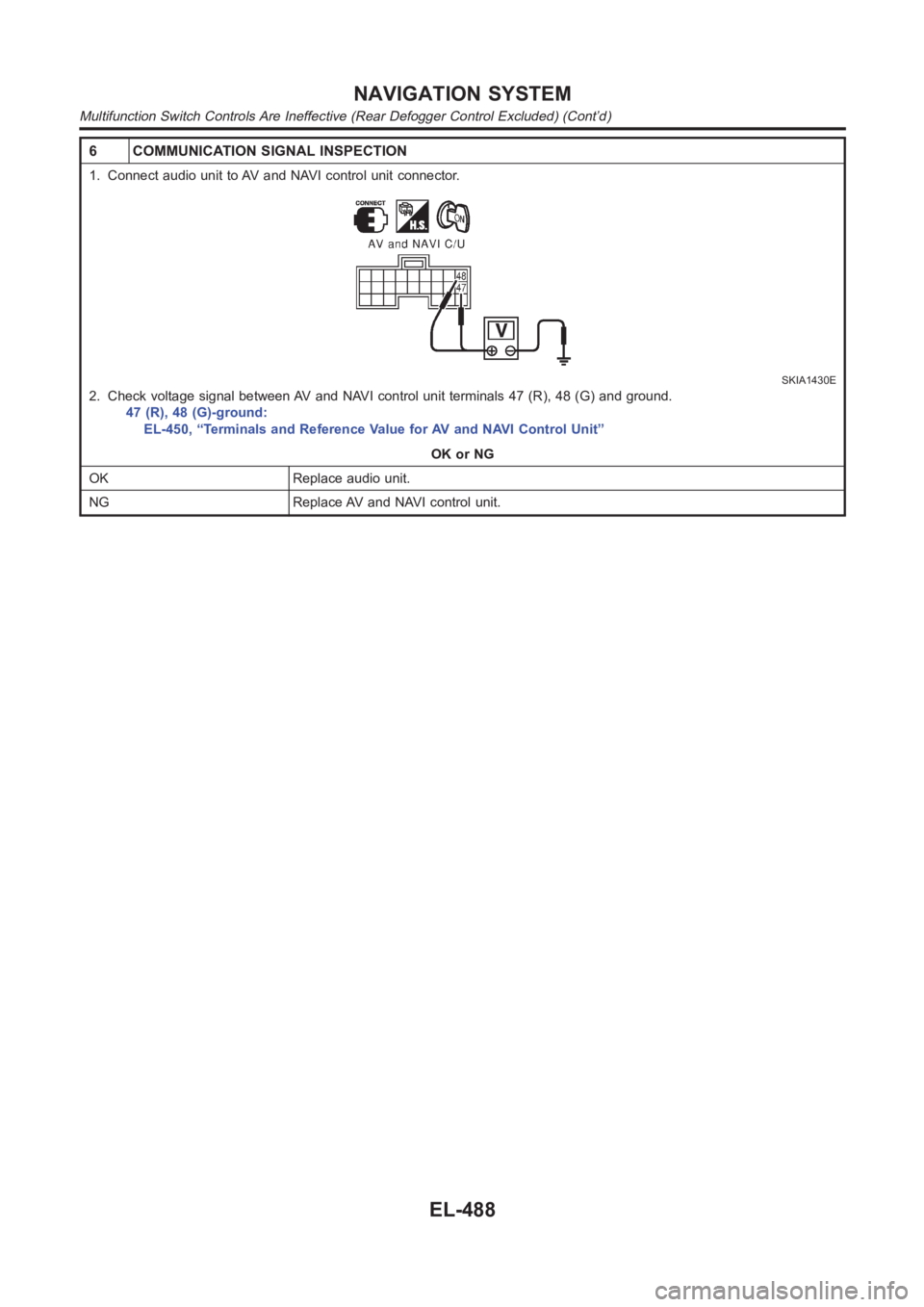
6 COMMUNICATION SIGNAL INSPECTION
1. Connect audio unit to AV and NAVI control unit connector.
SKIA1430E
2. Check voltage signal between AV and NAVI control unit terminals 47 (R), 48 (G) and ground.
47 (R), 48 (G)-ground:
EL-450, “Terminals and Reference Value for AV and NAVI Control Unit”
OK or NG
OK Replace audio unit.
NG Replace AV and NAVI control unit.
NAVIGATION SYSTEM
Multifunction Switch Controls Are Ineffective (Rear Defogger Control Excluded) (Cont’d)
EL-488
Page 2836 of 3189
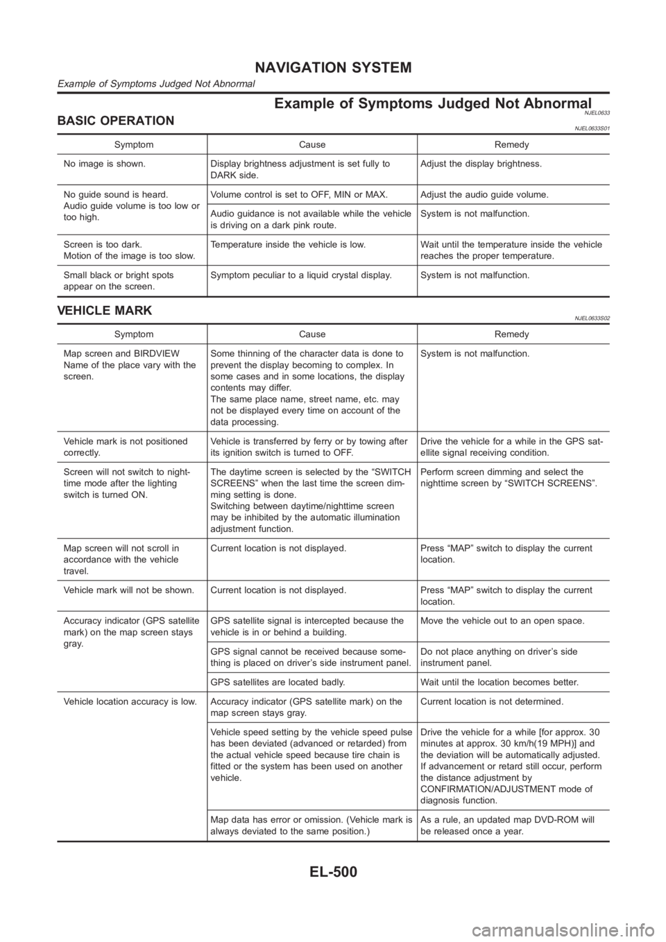
Example of Symptoms Judged Not AbnormalNJEL0633BASIC OPERATIONNJEL0633S01
Symptom Cause Remedy
No image is shown. Display brightness adjustment is set fully to
DARK side.Adjust the display brightness.
No guide sound is heard.
Audio guide volume is too low or
too high.Volume control is set to OFF, MIN or MAX. Adjust the audio guide volume.
Audio guidance is not available while the vehicle
is driving on a dark pink route.System is not malfunction.
Screen is too dark.
Motion of the image is too slow.Temperature inside the vehicle is low. Wait until the temperature inside the vehicle
reaches the proper temperature.
Small black or bright spots
appear on the screen.Symptom peculiar to a liquid crystal display. System is not malfunction.
VEHICLE MARKNJEL0633S02
Symptom Cause Remedy
Map screen and BIRDVIEW
Name of the place vary with the
screen.Some thinning of the character data is done to
prevent the display becoming to complex. In
some cases and in some locations, the display
contents may differ.
The same place name, street name, etc. may
not be displayed every time on account of the
data processing.System is not malfunction.
Vehicle mark is not positioned
correctly.Vehicle is transferred by ferry or by towing after
its ignition switch is turned to OFF.Drive the vehicle for a while in the GPS sat-
ellite signal receiving condition.
Screen will not switch to night-
time mode after the lighting
switch is turned ON.The daytime screen is selected by the “SWITCH
SCREENS” when the last time the screen dim-
ming setting is done.
Switching between daytime/nighttime screen
may be inhibited by the automatic illumination
adjustment function.Perform screen dimming and select the
nighttime screen by “SWITCH SCREENS”.
Map screen will not scroll in
accordance with the vehicle
travel.Current location is not displayed. Press “MAP” switch to display the current
location.
Vehicle mark will not be shown. Current location is not displayed. Press “MAP” switch to display the current
location.
Accuracy indicator (GPS satellite
mark) on the map screen stays
gray.GPS satellite signal is intercepted because the
vehicle is in or behind a building.Move the vehicle out to an open space.
GPS signal cannot be received because some-
thing is placed on driver’s side instrument panel.Do not place anything on driver’s side
instrument panel.
GPS satellites are located badly. Wait until the location becomes better.
Vehicle location accuracy is low. Accuracy indicator (GPS satellite mark)onthe
map screen stays gray.Current location is not determined.
Vehicle speed setting by the vehicle speed pulse
has been deviated (advanced or retarded) from
the actual vehicle speed because tire chain is
fitted or the system has been used on another
vehicle.Drive the vehicle for a while [for approx. 30
minutes at approx. 30 km/h(19 MPH)] and
the deviation will be automatically adjusted.
If advancement or retard still occur, perform
the distance adjustment by
CONFIRMATION/ADJUSTMENT mode of
diagnosis function.
Map data has error or omission. (Vehicle mark is
always deviated to the same position.)As a rule, an updated map DVD-ROM will
be released once a year.
NAVIGATION SYSTEM
Example of Symptoms Judged Not Abnormal
EL-500
Page 2935 of 3189
NJEL0311
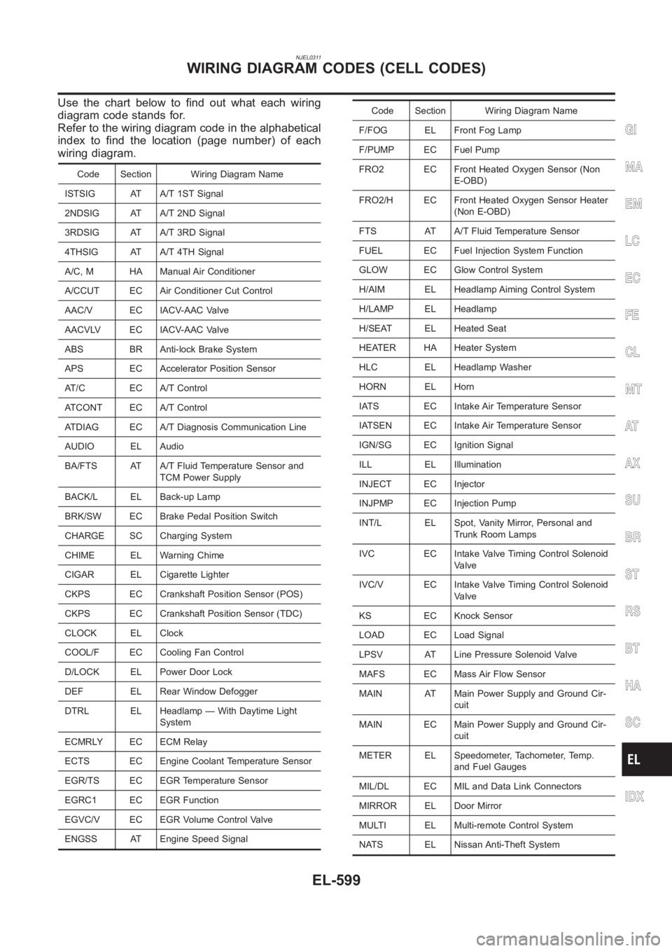
Use the chart below to find out what each wiring
diagram code stands for.
Refer to the wiring diagram code in the alphabetical
index to find the location (page number) of each
wiring diagram.
Code Section Wiring Diagram Name
ISTSIG AT A/T 1ST Signal
2NDSIG AT A/T 2ND Signal
3RDSIG AT A/T 3RD Signal
4THSIG AT A/T 4TH Signal
A/C, M HA Manual Air Conditioner
A/CCUT EC Air Conditioner Cut Control
AAC/V EC IACV-AAC Valve
AACVLV EC IACV-AAC Valve
ABS BR Anti-lock Brake System
APS EC Accelerator Position Sensor
AT/C EC A/T Control
ATCONT EC A/T Control
ATDIAG EC A/T Diagnosis Communication Line
AUDIO EL Audio
BA/FTS AT A/T Fluid Temperature Sensor and
TCM Power Supply
BACK/L EL Back-up Lamp
BRK/SW EC Brake Pedal Position Switch
CHARGE SC Charging System
CHIME EL Warning Chime
CIGAR EL Cigarette Lighter
CKPS EC Crankshaft Position Sensor (POS)
CKPS EC Crankshaft Position Sensor (TDC)
CLOCK EL Clock
COOL/F EC Cooling Fan Control
D/LOCK EL Power Door Lock
DEF EL Rear Window Defogger
DTRL EL Headlamp — With Daytime Light
System
ECMRLY EC ECM Relay
ECTS EC Engine Coolant Temperature Sensor
EGR/TS EC EGR Temperature Sensor
EGRC1 EC EGR Function
EGVC/V EC EGR Volume Control Valve
ENGSS AT Engine Speed Signal
Code Section Wiring Diagram Name
F/FOG EL Front Fog Lamp
F/PUMP EC Fuel Pump
FRO2 EC Front Heated Oxygen Sensor (Non
E-OBD)
FRO2/H EC Front Heated Oxygen Sensor Heater
(Non E-OBD)
FTS AT A/T Fluid Temperature Sensor
FUEL EC Fuel Injection System Function
GLOW EC Glow Control System
H/AIM EL Headlamp Aiming Control System
H/LAMP EL Headlamp
H/SEAT EL Heated Seat
HEATER HA Heater System
HLC EL Headlamp Washer
HORN EL Horn
IATS EC Intake Air Temperature Sensor
IATSEN EC Intake Air Temperature Sensor
IGN/SG EC Ignition Signal
ILL EL Illumination
INJECT EC Injector
INJPMP EC Injection Pump
INT/L EL Spot, Vanity Mirror, Personal and
Trunk Room Lamps
IVC EC Intake Valve Timing Control Solenoid
Valve
IVC/V EC Intake Valve Timing Control Solenoid
Valve
KS EC Knock Sensor
LOAD EC Load Signal
LPSV AT Line Pressure Solenoid Valve
MAFS EC Mass Air Flow Sensor
MAIN AT Main Power Supply and Ground Cir-
cuit
MAIN EC Main Power Supply and Ground Cir-
cuit
METER EL Speedometer, Tachometer, Temp.
and Fuel Gauges
MIL/DL EC MIL and Data Link Connectors
MIRROR EL Door Mirror
MULTI EL Multi-remote Control System
NATS EL Nissan Anti-Theft System
GI
MA
EM
LC
EC
FE
CL
MT
AT
AX
SU
BR
ST
RS
BT
HA
SC
IDX
WIRING DIAGRAM CODES (CELL CODES)
EL-599
Page 3062 of 3189
SHIA0239E
SRS443
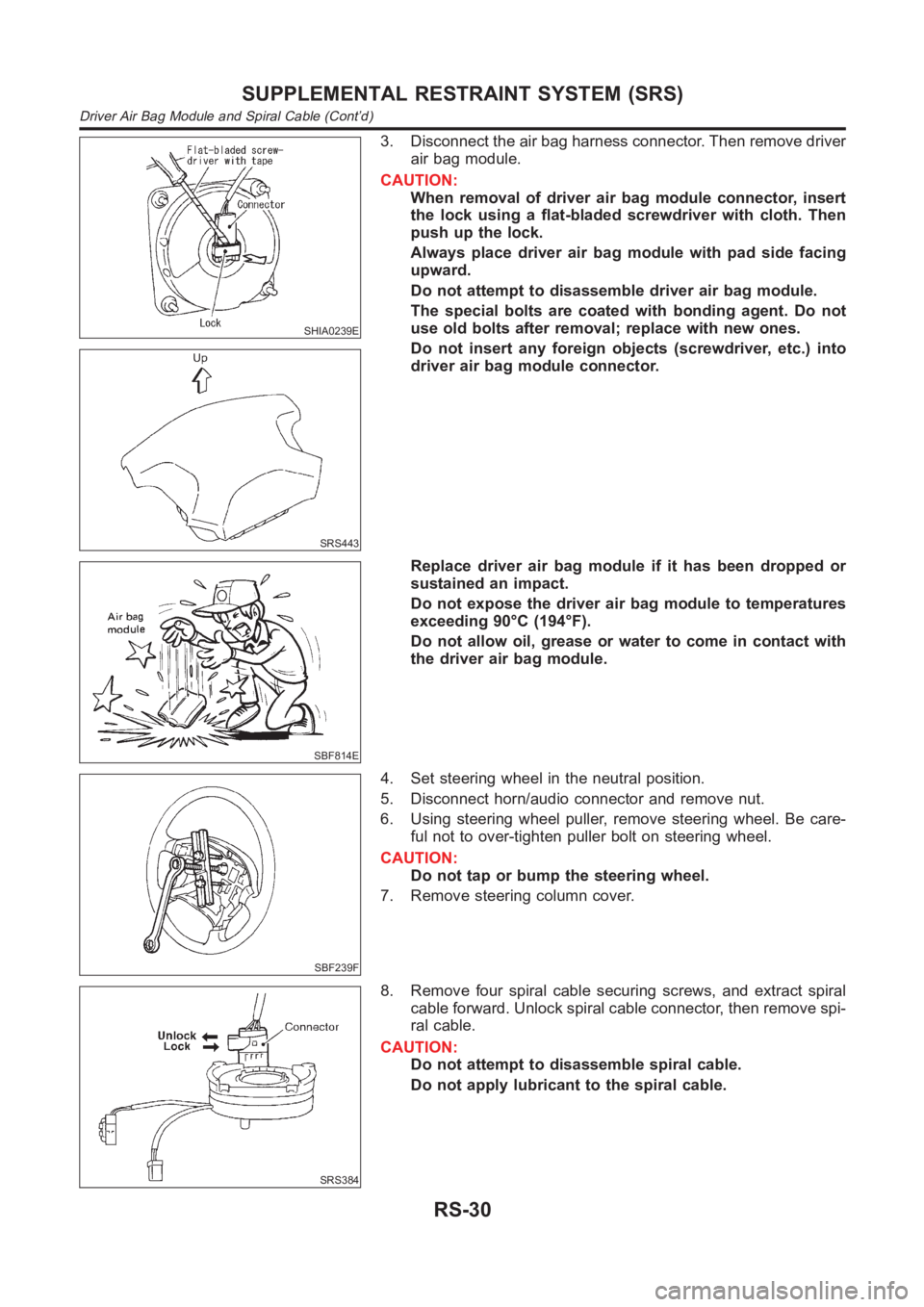
3. Disconnect the air bag harness connector. Then remove driver
air bag module.
CAUTION:
When removal of driver air bag module connector, insert
the lock using a flat-bladed screwdriver with cloth. Then
push up the lock.
Always place driver air bag module with pad side facing
upward.
Do not attempt to disassemble driver air bag module.
The special bolts are coated with bonding agent. Do not
use old bolts after removal; replace with new ones.
Do not insert any foreign objects (screwdriver, etc.) into
driver air bag module connector.
SBF814E
Replace driver air bag module if it has been dropped or
sustained an impact.
Do not expose the driver air bag module to temperatures
exceeding 90°C (194°F).
Do not allow oil, grease or water to come in contact with
the driver air bag module.
SBF239F
4. Set steering wheel in the neutral position.
5. Disconnect horn/audio connector and remove nut.
6. Using steering wheel puller, remove steering wheel. Be care-
ful not to over-tighten puller bolt on steering wheel.
CAUTION:
Do not tap or bump the steering wheel.
7. Remove steering column cover.
SRS384
8. Remove four spiral cable securing screws, and extract spiral
cable forward. Unlock spiral cable connector, then remove spi-
ral cable.
CAUTION:
Do not attempt to disassemble spiral cable.
Do not apply lubricant to the spiral cable.
SUPPLEMENTAL RESTRAINT SYSTEM (SRS)
Driver Air Bag Module and Spiral Cable (Cont’d)
RS-30
Page 3063 of 3189
NRS121
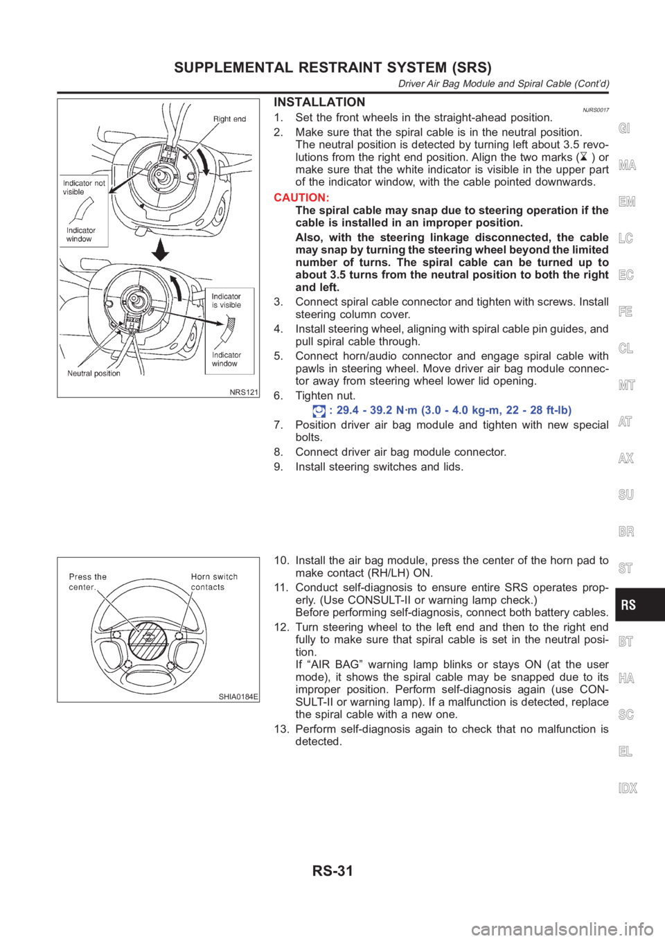
INSTALLATIONNJRS00171. Set the front wheels in the straight-ahead position.
2. Make sure that the spiral cable is in the neutral position.
The neutral position is detected by turning left about 3.5 revo-
lutions from the right end position. Align the two marks (
)or
make sure that the white indicator is visible in the upper part
of the indicator window, with the cable pointed downwards.
CAUTION:
The spiral cable may snap due to steering operation if the
cable is installed in an improper position.
Also, with the steering linkage disconnected, the cable
may snap by turning the steering wheel beyond the limited
number of turns. The spiral cable can be turned up to
about 3.5 turns from the neutral position to both the right
and left.
3. Connect spiral cable connector and tighten with screws. Install
steering column cover.
4. Install steering wheel, aligning with spiral cable pin guides, and
pull spiral cable through.
5. Connect horn/audio connector and engage spiral cable with
pawls in steering wheel. Move driver air bag module connec-
tor away from steering wheel lower lid opening.
6. Tighten nut.
: 29.4 - 39.2 N·m (3.0 - 4.0 kg-m, 22 - 28 ft-lb)
7. Position driver air bag module and tighten with new special
bolts.
8. Connect driver air bag module connector.
9. Install steering switches and lids.
SHIA0184E
10. Install the air bag module, press the center of the horn pad to
make contact (RH/LH) ON.
11. Conduct self-diagnosis to ensure entire SRS operates prop-
erly. (Use CONSULT-II or warning lamp check.)
Before performing self-diagnosis, connect both battery cables.
12. Turn steering wheel to the left end and then to the right end
fully to make sure that spiral cable is set in the neutral posi-
tion.
If “AIR BAG” warning lamp blinks or stays ON (at the user
mode), it shows the spiral cable may be snapped due to its
improper position. Perform self-diagnosis again (use CON-
SULT-II or warning lamp). If a malfunction is detected, replace
the spiral cable with a new one.
13. Perform self-diagnosis again to check that no malfunction is
detected.
GI
MA
EM
LC
EC
FE
CL
MT
AT
AX
SU
BR
ST
BT
HA
SC
EL
IDX
SUPPLEMENTAL RESTRAINT SYSTEM (SRS)
Driver Air Bag Module and Spiral Cable (Cont’d)
RS-31