2003 NISSAN ALMERA N16 gauge
[x] Cancel search: gaugePage 31 of 3189

strand will have a high resistance to the current. This will be picked
up as a slight voltage drop.
Unwanted resistance can be caused by many situations as follows:
Undersized wiring (single strand example)
Corrosion on switch contacts
Loose wire connections or splices.
If repairs are needed always use wire that is of the same or larger
gauge.
Measuring Voltage Drop — Accumulated Method
1) Connect the voltmeter across the connector or part of the cir-
cuit you want to check. The positive lead of the voltmeter
should be closer to power and the negative lead closer to
ground.
2) Operate the circuit.
3) The voltmeter will indicate how many volts are being used to
“push” current through that part of the circuit.
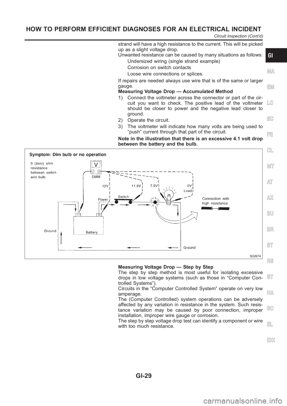
Note in the illustration that there is an excessive 4.1 volt drop
between the battery and the bulb.
SGI974
Measuring Voltage Drop — Step by Step
The step by step method is most useful for isolating excessive
drops in low voltage systems (such as those in “Computer Con-
trolled Systems”).
Circuits in the “Computer Controlled System” operate on very low
amperage.
The (Computer Controlled) system operations can be adversely
affected by any variation in resistance in the system. Such resis-
tance variation may be caused by poor connection, improper
installation, improper wire gauge or corrosion.
The step by step voltage drop test can identify a component or wire
with too much resistance.
MA
EM
LC
EC
FE
CL
MT
AT
AX
SU
BR
ST
RS
BT
HA
SC
EL
IDX
HOW TO PERFORM EFFICIENT DIAGNOSES FOR AN ELECTRICAL INCIDENT
Circuit Inspection (Cont’d)
GI-29
Page 58 of 3189

NJMA0036
Shown below are Pre-delivery Inspection Items required for the new vehicle. It is recommended that
necessary items other than those listed here be added, paying due regard tothe conditions in each
country.
Perform applicable items on each model. Consult text of this section for specifications.
UNDER HOOD — engine off
Radiator coolant level and coolant hose connections for leaks
Battery fluid level, specific gravity and conditions of battery terminals
Drive belts tension
Fuel filter for water or dusts (Diesel only), and fuel lines and connections for leaks
Engine oil level and oil leaks
Clutch and brake reservoir fluid level and fluid lines for leaks
Windshield and rear window washer and headlamp cleaner reservoir fluid level
Power steering reservoir fluid level and hose connections for leaks
ON INSIDE AND OUTSIDE
Remove front spring/strut spacer (If applicable)
Operation of all instruments, gauges, lights and accessories
Operation of horn(s), wiper and washer
Steering lock for operation
Check air conditioner for gas leaks
Front and rear seats, and seat belts for operation
All moldings, trims and fittings for fit and alignment
All windows for operation and alignment
Hood, trunk lid, door panels for fit and alignment
Latches, keys and locks for operation
Weatherstrips for adhesion and fit
Headlamp aiming
Tighten wheel nuts (Inc. inner nuts if applicable)
Tire pressure (Inc. spare tire)
Check front wheels for toe-in
Install clock/voltmeter/room lamp fuse (If applicable)
Install deodorizing filter to air conditioner (If applicable)
Remove wiper blade protectors (If applicable)
UNDER BODY
Manual transmission/transaxle, transfer and differential gear oil level
Brake and fuel lines and oil/fluid reservoirs for leaks
Tighten bolts and nuts of steering linkage and gear box, suspension, propeller shafts and drive shafts
Tighten rear body bolts and nuts (Models with wooden bed only)
ROAD TEST
Clutch operation
Parking brake operation
Service brake operation
Automatic transmission/transaxle shift timing and kickdown
Steering control and returnability
Engine performance
Squeaks and rattles
ENGINE OPERATING AND HOT
Adjust idle speed
Automatic transmission/transaxle fluid level
Engine idling and stop knob operation (Diesel only)
FINAL INSPECTION
Install necessary parts (outside mirror, wheel covers, seat belts, mat, carpet or mud flaps)
Inspect for interior and exterior metal and paint damage
Check for spare tire, jack, tools (wheel chock), and literature
Wash, clean interior and exterior
: Not applicable to this model
PRE-DELIVERY INSPECTION ITEMS
MA-2
Page 59 of 3189

NJMA0004
General maintenance includes those items which should be checked during the normal day-to-day operation
of the vehicle. They are essential if the vehicle is to continue operating properly. The owners can perform the
checks and inspections themselves or they can have their NISSAN dealers dothem for a nominal charge.
OUTSIDE THE VEHICLE
The maintenance items listed here should be performed from time to time, unless otherwise specified.
Item Reference page
TiresCheck the pressure with a gauge periodically when at a service station,
including the spare, and adjust to the specified pressure if necessary. Check
carefully for damage, cuts or excessive wear.—
Windshield wiper
bladesCheck for cracks or wear if not functioning correctly. —
Doors and engine
hoodCheck that all doors, the engine hood, the trunk lid and back door operate
properly. Also ensure that all latches lock securely. Lubricate if necessary.
Make sure that the secondary latch keeps the hood from opening when the
primary latch is released.
When driving in areas using road salt or other corrosive materials, check for
lubrication frequently.BT-7
BT-16
Tire rotationTires should be rotated every 10,000 km (6,000 miles). SU-7
INSIDE THE VEHICLE
The maintenance items listed here should be checked on a regular basis, such as when performing periodic maintenance, cleaning the
vehicle, etc.
Item Reference page
LampsMake sure that the headlamps, stop lamps, tail lamps, turn signal lamps,
and other lamps are all operating properly and installed securely. Also check
headlamp aim.—
Warning lamps and
chimesMake sure that all warning lamps and buzzers/chimes are operating prop-
erly.—
Steering wheelCheck that it has the specified play.
Check for changes in the steering conditions, such as excessive free play,
hard steering or strange noises.
Free play: Less than 35 mm (1.38 in)—
Seat beltsCheck that all parts of the seat belt system (e.g. buckles, anchors, adjusters
and retractors) operate properly and smoothly, and are installed securely.
Check the belt webbing for cuts, fraying, wear or damage.RS-4
UNDER THE HOOD AND VEHICLE
The maintenance items listed here should be checked periodically e.g. each time you check the engine oil or refuel.
Item Reference page
Windshield washer
fluidCheck that there is adequate fluid in the tank. —
Engine coolant levelCheck the coolant level when the engine is cold. LC-18, LC-43
Engine oil levelCheck the level after parking the vehicle (on level ground) and turning off
the engine.LC-8, LC-30
Brake and clutch
fluid levelsMake sure that the brake and clutch fluid levels are between the “MAX” and
“MIN” lines on the reservoir.BR-7
BatteryCheck the fluid level in each cell. It should be between the “MAX” and “MIN”
lines.—
GI
EM
LC
EC
FE
CL
MT
AT
AX
SU
BR
ST
RS
BT
HA
SC
EL
IDX
GENERAL MAINTENANCE
MA-3
Page 96 of 3189
![NISSAN ALMERA N16 2003 Electronic Repair Manual EM-18
[QG]
INTAKE MANIFOLD
INSPECTION AFTER REMOVAL
Surface Distortion
●Using straightedge and feeler gauge, inspect surface distortion
of intake manifold collector and intake manifold surfac NISSAN ALMERA N16 2003 Electronic Repair Manual EM-18
[QG]
INTAKE MANIFOLD
INSPECTION AFTER REMOVAL
Surface Distortion
●Using straightedge and feeler gauge, inspect surface distortion
of intake manifold collector and intake manifold surfac](/manual-img/5/57350/w960_57350-95.png)
EM-18
[QG]
INTAKE MANIFOLD
INSPECTION AFTER REMOVAL
Surface Distortion
●Using straightedge and feeler gauge, inspect surface distortion
of intake manifold collector and intake manifold surface.
INSTALLATION
●Install in the reverse order of removal paying attention to the following.
Tightening Intake Manifold
●Temporarily attach before installing intake manifold collector.
●Tighten in numerical order as shown in the figure.
Tightening Intake Manifold Collector
●Temporarily attach before installing intake manifold.
●Tighten in numerical order as shown in the figure.
Installation of Electric Throttle Control Actuator
●Tighten mounting bolts for electric throttle control actuator in
numerical order shown in figure.
CAUTION:
When electric throttle control actuator is replaced, perform
idle air volume learning.
●Refer to BASIC SERVICE PROCEDURE, EC-31, "Idle Air Vol-
ume Learning" (WITH EURO-OBD), EC-425, "Idle Air Volume
Learning" (WITHOUT EURO-OBD). Limit : 0.1 mm (0.004 in)
PBIC0536E
PBIC0535E
KBIA1366E
: 17.7 - 21.6 N·m (1.8 - 2.2 kg-m, 13 - 15 ft-lb)
PBIC0534E
Page 98 of 3189
![NISSAN ALMERA N16 2003 Electronic Repair Manual EM-20
[QG]
EXHAUST MANIFOLD AND CATALYTIC CONVERTER
●Using heated oxygen sensor wrench, remove heated oxygen
sensor.
CAUTION:
●Be careful not to damage heated oxygen sensor.
●When using heate NISSAN ALMERA N16 2003 Electronic Repair Manual EM-20
[QG]
EXHAUST MANIFOLD AND CATALYTIC CONVERTER
●Using heated oxygen sensor wrench, remove heated oxygen
sensor.
CAUTION:
●Be careful not to damage heated oxygen sensor.
●When using heate](/manual-img/5/57350/w960_57350-97.png)
EM-20
[QG]
EXHAUST MANIFOLD AND CATALYTIC CONVERTER
●Using heated oxygen sensor wrench, remove heated oxygen
sensor.
CAUTION:
●Be careful not to damage heated oxygen sensor.
●When using heated oxygen sensor wrench, tighten to the
middle of specified torque because length of tool may
induce sight indication increase. (Do not tighten to the
maximum specified torque)
●Do not over torque the heated oxygen sensor. Doing so
may cause damage to the heated oxygen sensor, result-
ing in the MI coming on.
6. Remove exhaust manifold cover.
7. Loosen mounting nuts in reverse order shown in figure to
remove exhaust manifold and catalytic converter assembly.
INSPECTION AFTER REMOVAL
Surface Distortion
●Use a reliable straightedge and feeler gauge to check the flat-
ness of exhaust manifold fitting surface.
INSTALLATION
●Install in the reverse order of removal after this step.
●Tighten mounting nuts for exhaust manifold and catalytic con-
verter assembly in order shown in figure.
●Before installing exhaust manifold support, apply liquid gasket to
contact surface on engine side.
Use Genuine Liquid Gasket or equivalent.
Installation of Heated Oxygen Sensor
CAUTION:
●Do not over torque the heated oxygen sensor. Doing so may cause damage to the heated oxygen
sensor, resulting in the MI coming on.
PBIC0541E
PBIC0542E
Limit : 0.3 mm (0.012 in)
PBIC0543E
PBIC0542E
Page 117 of 3189
![NISSAN ALMERA N16 2003 Electronic Repair Manual CAMSHAFT
EM-39
[QG]
C
D
E
F
G
H
I
J
K
L
MA
EM
INSPECTION AFTER REMOVAL
Camshaft Runout
●Place a V-block on a surface plate to support No. 2 and No. 5
journals on camshaft.
CAUTION:
Do NISSAN ALMERA N16 2003 Electronic Repair Manual CAMSHAFT
EM-39
[QG]
C
D
E
F
G
H
I
J
K
L
MA
EM
INSPECTION AFTER REMOVAL
Camshaft Runout
●Place a V-block on a surface plate to support No. 2 and No. 5
journals on camshaft.
CAUTION:
Do](/manual-img/5/57350/w960_57350-116.png)
CAMSHAFT
EM-39
[QG]
C
D
E
F
G
H
I
J
K
L
MA
EM
INSPECTION AFTER REMOVAL
Camshaft Runout
●Place a V-block on a surface plate to support No. 2 and No. 5
journals on camshaft.
CAUTION:
Do not support No. 1 journal (camshaft sprocket mounting
side), because its diameter is different from that of the other
4 journals.
●Set a dial gauge vertically onto journal No. 3.
●Rotate the camshaft in one direction by hand and read indication
on the gauge.
●A half of reading value is actual bend.
Camshaft Cam Height
●Measure with a micrometer.
Camshaft Journal Clearance
Outer Diameter of Camshaft Journal
●Measure with a micrometer.
Inner Diameter of Camshaft Bracket
●Tighten camshaft bracket bolts to the specified torque.
●Using an inside micrometer, measure inner diameter of the cam-
shaft bracket.
Calculation of Camshaft Journal Clearance
(Oil clearance) = (Camshaft bracket inner diameter) - (Camshaft journal outer diameter) Standard : 0.02 mm (0.0008 in) or less
MBIB0215E
Intake : 40.217 - 40.407 mm (1.5833 - 1.5908 in)
Exhaust : 38.965 - 39.155 mm (1.5341 - 1.5415 in)
MBIB0216E
Standard
No. 1
: 27.935 - 27.955 mm (1.0998 - 1.1006 in) dia.
No. 2 to No. 5
: 23.935 - 23.955 mm (0.9423 - 0.9431 in) dia.
MBIB0217E
Standard
No. 1
: 28.000 - 28.021 mm (1.1024 - 1.1032 in) dia.
No. 2 to No. 5
: 23.985 - 24.006 mm (0.9443 - 0.9451 in) dia.
MBIB0218E
Page 118 of 3189
![NISSAN ALMERA N16 2003 Electronic Repair Manual EM-40
[QG]
CAMSHAFT
●If outside the standard, refer to standard of each unit part and replace camshaft or cylinder head as appro-
priate.
NOTE:
Camshaft bracket is machined with cylinder head. Repla NISSAN ALMERA N16 2003 Electronic Repair Manual EM-40
[QG]
CAMSHAFT
●If outside the standard, refer to standard of each unit part and replace camshaft or cylinder head as appro-
priate.
NOTE:
Camshaft bracket is machined with cylinder head. Repla](/manual-img/5/57350/w960_57350-117.png)
EM-40
[QG]
CAMSHAFT
●If outside the standard, refer to standard of each unit part and replace camshaft or cylinder head as appro-
priate.
NOTE:
Camshaft bracket is machined with cylinder head. Replace them as cylinder head assembly.
Camshaft End play
●Position a dial gauge onto front end of camshaft in thrust direc-
tion. Read indication of dial gauge while moving camshaft back
and forth (axial direction).
●If outside the standard, replace camshaft with new one. Then
measure it again.
●If still outside the standard, replace cylinder head with new one.
Camshaft Sprocket Runout
●Using a dial gauge, measure camshaft sprocket runout.
Valve Lifter and Adjusting Shim (Shim type)
Check surfaces of valve lifter and shim for cracks and wear.
Valve Lifter Clearance
Outer Diameter of Valve LifterStandard
No. 1
: 0.045 - 0.086 mm (0.0018 - 0.0028 in)
No. 2 to No. 5
: 0.030 - 0.071 mm (0.0012 - 0.0028 in)
Standard
Intake : 0.070 - 0.143 mm (0.0028 - 0.0056 in)
Exhaust : 0.115 - 0.188 mm (0.0045 - 0.0074 in)
MBIB0219E
Limit:
Intake : 0.2 mm (0.008 in)
Exhaust : 0.15 mm (0.0059 in)
PBIC0930E
SEM160D
Page 120 of 3189
![NISSAN ALMERA N16 2003 Electronic Repair Manual EM-42
[QG]
CAMSHAFT
Valve Lifter Hole Diameter
●Using inside micrometer, measure diameter of valve lifter hole of
cylinder head.
Calculation of Valve Lifter Clearance
(Valve lifter clearance) = (hol NISSAN ALMERA N16 2003 Electronic Repair Manual EM-42
[QG]
CAMSHAFT
Valve Lifter Hole Diameter
●Using inside micrometer, measure diameter of valve lifter hole of
cylinder head.
Calculation of Valve Lifter Clearance
(Valve lifter clearance) = (hol](/manual-img/5/57350/w960_57350-119.png)
EM-42
[QG]
CAMSHAFT
Valve Lifter Hole Diameter
●Using inside micrometer, measure diameter of valve lifter hole of
cylinder head.
Calculation of Valve Lifter Clearance
(Valve lifter clearance) = (hole diameter of valve lifter) – (outer diam-
eter of valve lifter).
●When out of specified range, referring to each specification of outer and inner diameter, replace either or
both valve lifter and cylinder head.
Valve ClearanceEBS00LQC
INSPECTION
●The following procedure is applicable when: Components related to camshafts or valves are removed,
installed, or replaced. Drivability concerns (poor starting, poor idling, noise) are caused by valve clearance
aging.
1. Warm up engine, and stop.
2. Remove RH splash cover (integrated with undercover).
3. Remove rocker cover. Refer to EM-29, "
ROCKER COVER" .
4. Turn crankshaft pulley clockwise (viewed from front) to align yel-
low paint with timing indicator.
5. At this point, confirm that both intake and exhaust cam noses on
No. 1 cylinder face outward. (No. 1 cylinder is at TDC of its com-
pression stroke.)
●If not, turn crankshaft pulley more.
NOTE:
Or, valves to be checked when No. 4 cylinder is at TDC of its
compression stroke can be checked first following step 8.
6. Referring to figure, measure valve clearances of valves with × in
table below using a thickness gauge.Standard (Intake and exhaust)
: 30.000 - 30.021 mm (1.1811 - 1.1819 in) dia.
Standard (Intake and exhaust)
: 0.025 - 0.061 mm (0.0010 - 0.0024 in)
SEM867E
MBIB0222E
Cylinder No.1 No.2 No.3 No.4
Valve INT EXH INT EXH INT EXH INT EXH
No. 1 cylinder at
TDC of its compres-
sion stroke××× ×
MBIB0223E
MBIB0224E