Page 2548 of 3189
YEL735D
AUDIO
Wiring Diagram — AUDIO — (Cont’d)
EL-212
Page 2549 of 3189

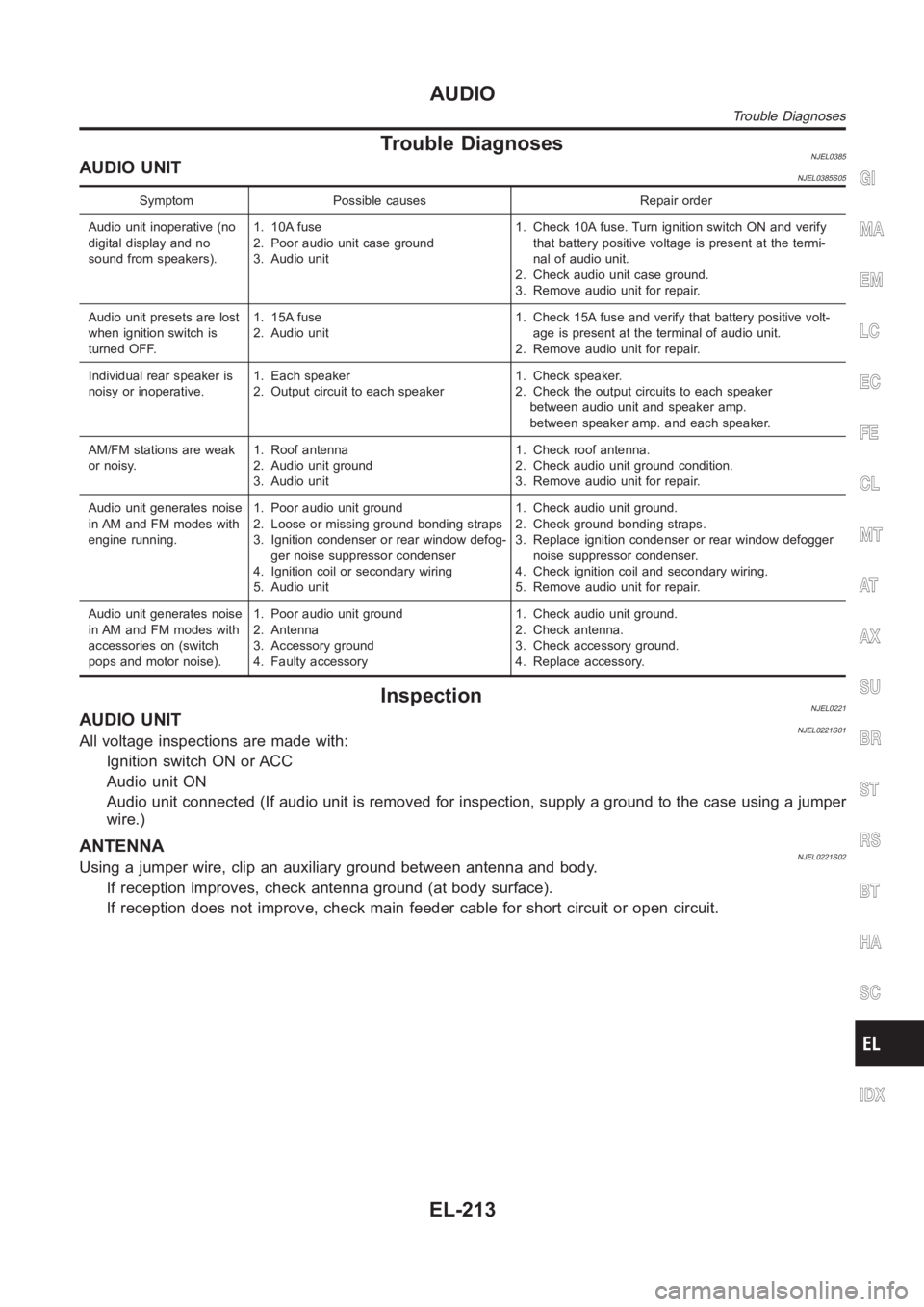
Trouble DiagnosesNJEL0385AUDIO UNITNJEL0385S05
Symptom Possible causes Repair order
Audio unit inoperative (no
digital display and no
sound from speakers).1. 10A fuse
2. Poor audio unit case ground
3. Audio unit1. Check 10A fuse. Turn ignition switch ON and verify
that battery positive voltage is present at the termi-
nal of audio unit.
2. Check audio unit case ground.
3. Remove audio unit for repair.
Audio unit presets are lost
when ignition switch is
turned OFF.1. 15A fuse
2. Audio unit1. Check 15A fuse and verify that battery positive volt-
age is present at the terminal of audio unit.
2. Remove audio unit for repair.
Individual rear speaker is
noisy or inoperative.1. Each speaker
2. Output circuit to each speaker1. Check speaker.
2. Check the output circuits to each speaker
between audio unit and speaker amp.
between speaker amp. and each speaker.
AM/FM stations are weak
or noisy.1. Roof antenna
2. Audio unit ground
3. Audio unit1. Check roof antenna.
2. Check audio unit ground condition.
3. Remove audio unit for repair.
Audio unit generates noise
in AM and FM modes with
engine running.1. Poor audio unit ground
2. Loose or missing ground bonding straps
3. Ignition condenser or rear window defog-
ger noise suppressor condenser
4. Ignition coil or secondary wiring
5. Audio unit1. Check audio unit ground.
2. Check ground bonding straps.
3. Replace ignition condenser or rear window defogger
noise suppressor condenser.
4. Check ignition coil and secondary wiring.
5. Remove audio unit for repair.
Audio unit generates noise
in AM and FM modes with
accessories on (switch
pops and motor noise).1. Poor audio unit ground
2. Antenna
3. Accessory ground
4. Faulty accessory1. Check audio unit ground.
2. Check antenna.
3. Check accessory ground.
4. Replace accessory.
InspectionNJEL0221AUDIO UNITNJEL0221S01All voltage inspections are made with:
Ignition switch ON or ACC
Audio unit ON
Audio unit connected (If audio unit is removed for inspection, supply a ground to the case using a jumper
wire.)
ANTENNANJEL0221S02Using a jumper wire, clip an auxiliary ground between antenna and body.
If reception improves, check antenna ground (at body surface).
If reception does not improve, check main feeder cable for short circuit oropen circuit.
GI
MA
EM
LC
EC
FE
CL
MT
AT
AX
SU
BR
ST
RS
BT
HA
SC
IDX
AUDIO
Trouble Diagnoses
EL-213
Page 2550 of 3189
Location of AntennaNJEL0468
YEL825D
YEL826D
Antenna Rod ReplacementNJEL0469REMOVALNJEL0469S011. Remove front portion of headliner.
2. Remove antenna base cover.
3. Remove antenna base fixing nut and antenna base.
AUDIO ANTENNA
Location of Antenna
EL-214
Page 2551 of 3189

System DescriptionNJEL0555MULTIFUNCTION SWITCH SYSTEMNJEL0555S01Refer to Owner′s Manual for multifunction switch operating instruc-
tions.
Using the multifunction switch at the center of the instrument panel,
it can be operating the following systems:
Auto A/C system
Board computer
Audio system
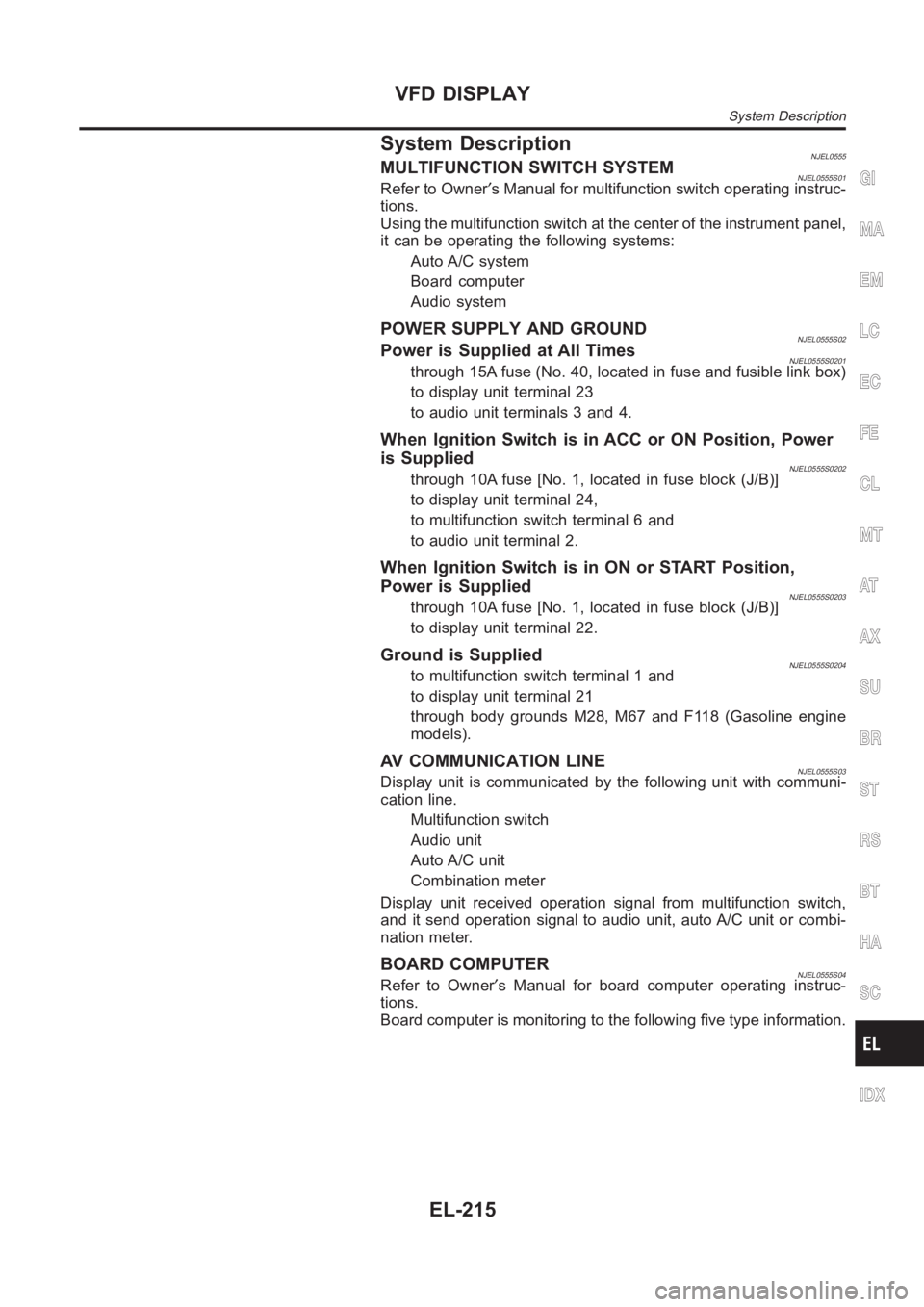
POWER SUPPLY AND GROUNDNJEL0555S02Power is Supplied at All TimesNJEL0555S0201through 15A fuse (No. 40, located in fuse and fusible link box)
to display unit terminal 23
to audio unit terminals 3 and 4.
When Ignition Switch is in ACC or ON Position, Power
is Supplied
NJEL0555S0202through 10A fuse [No. 1, located in fuse block (J/B)]
to display unit terminal 24,
to multifunction switch terminal 6 and
to audio unit terminal 2.
When Ignition Switch is in ON or START Position,
Power is Supplied
NJEL0555S0203through 10A fuse [No. 1, located in fuse block (J/B)]
to display unit terminal 22.
Ground is SuppliedNJEL0555S0204to multifunction switch terminal 1 and
to display unit terminal 21
through body grounds M28, M67 and F118 (Gasoline engine
models).
AV COMMUNICATION LINENJEL0555S03Display unit is communicated by the following unit with communi-
cation line.
Multifunction switch
Audio unit
Auto A/C unit
Combination meter
Display unit received operation signal from multifunction switch,
and it send operation signal to audio unit, auto A/C unit or combi-
nation meter.
BOARD COMPUTERNJEL0555S04Refer to Owner′s Manual for board computer operating instruc-
tions.
Board computer is monitoring to the following five type information.
GI
MA
EM
LC
EC
FE
CL
MT
AT
AX
SU
BR
ST
RS
BT
HA
SC
IDX
VFD DISPLAY
System Description
EL-215
Page 2558 of 3189
TERMINALS
SIGNALCONDITION
DATA (+)
(–)
TERMINALWIRE
COLORIGNITION
SWITCHOPERATION
12 B/W GroundCommunication
signal (+)ON —
SKIA0175E
13 P GroundCommunication
signal (−)ON —
SKIA0176E
14 L GroundCommunication
signal (−)ON —
SKIA0176E
15 — Ground Shield ground ON — —
16 — Ground Shield ground ON — —
Trouble DiagnosisNJEL0637SELF-DIAGNOSIS FUNCTIONNJEL0637S01DescriptionNJEL0637S0101Self-diagnosis items are as follows.
Screen of all segments check
Software version and hardware version of display unit are dis-
played on the upper zone of the screen. (This information is not
used for service. Skip this step.)
Dimming steps and levels check
Can be checked communication line between A/C auto amp.,
audio unit, multifunction switch, combination meter and display
unit, and displays the results on the upper zone of the screen.
VFD DISPLAY
Terminals and Reference Value for Multifunction Switch (Cont’d)
EL-222
Page 2559 of 3189

YEL828D
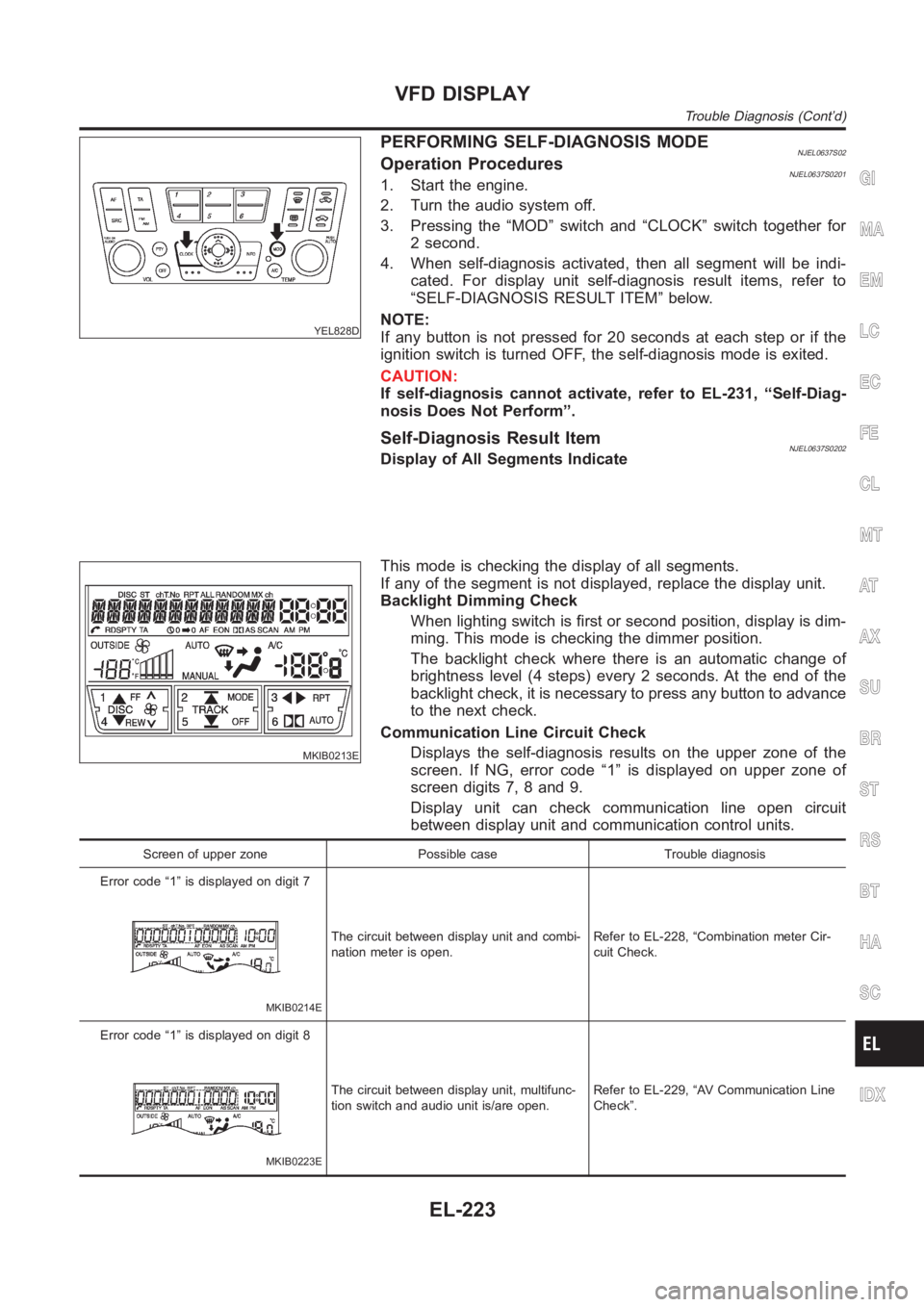
PERFORMING SELF-DIAGNOSIS MODENJEL0637S02Operation ProceduresNJEL0637S02011. Start the engine.
2. Turn the audio system off.
3. Pressing the “MOD” switch and “CLOCK” switch together for
2 second.
4. When self-diagnosis activated, then all segment will be indi-
cated. For display unit self-diagnosis result items, refer to
“SELF-DIAGNOSIS RESULT ITEM” below.
NOTE:
If any button is not pressed for 20 seconds at each step or if the
ignition switch is turned OFF, the self-diagnosis mode is exited.
CAUTION:
If self-diagnosis cannot activate, refer to EL-231, “Self-Diag-
nosis Does Not Perform”.
Self-Diagnosis Result ItemNJEL0637S0202Display of All Segments Indicate
MKIB0213E
This mode is checking the display of all segments.
If any of the segment is not displayed, replace the display unit.
Backlight Dimming Check
When lighting switch is first or second position, display is dim-
ming. This mode is checking the dimmer position.
The backlight check where there is an automatic change of
brightness level (4 steps) every 2 seconds. At the end of the
backlight check, it is necessary to press any button to advance
to the next check.
Communication Line Circuit Check
Displays the self-diagnosis results on the upper zone of the
screen. If NG, error code “1” is displayed on upper zone of
screen digits 7, 8 and 9.
Display unit can check communication line open circuit
between display unit and communication control units.
Screen of upper zone Possible case Trouble diagnosis
Error code “1” is displayed on digit 7
MKIB0214E
The circuit between display unit and combi-
nation meter is open.Refer to EL-228, “Combination meter Cir-
cuit Check.
Error code “1” is displayed on digit 8
MKIB0223E
The circuit between display unit, multifunc-
tion switch and audio unit is/are open.Refer to EL-229, “AV Communication Line
Check”.
GI
MA
EM
LC
EC
FE
CL
MT
AT
AX
SU
BR
ST
RS
BT
HA
SC
IDX
VFD DISPLAY
Trouble Diagnosis (Cont’d)
EL-223
Page 2566 of 3189
2 AUDIO UNIT CIRCUIT CHECK
1. Turn ignition switch OFF.
YEL830D
2. Disconnect audio unit connector.
3. Check continuity between multifunction switch and audio unit.
MTBL1469
4. Check continuity between multifunction switch and ground.
MTBL1470
OK or NG
OK Replace display unit.
NG Replace harness or connector.
VFD DISPLAY
Trouble Diagnosis (Cont’d)
EL-230
Page 2568 of 3189
3 SELF-DIAGNOSIS CHECK
1. Disconnect audio unit connector M53.
2. Perform self-diagnosis mode. Refer to EL-223, “Performing Self-Diagnosis Mode”.
Does Self-diagnosis activated?
Ye s G O T O 4 .
No AV communication line check. Refer to EL-229, “AV Communication Line Check”.
4 MULTIFUNCTION SWITCH CIRCUIT CHECK
1. Disconnect multifunction switch connector.
YEL830D
2. Check continuity between multifunction switch and audio unit.
MTBL1473
3. Check continuity between multifunction switch and ground.
MTBL1474
OK or NG
OK Replace display unit.
NG Replace harness or connector.
VFD DISPLAY
Trouble Diagnosis (Cont’d)
EL-232