2003 NISSAN ALMERA N16 audio
[x] Cancel search: audioPage 2574 of 3189
System DescriptionNJEL0571MULTIFUNCTION SWITCH SYSTEMNJEL0571S01Refer to Owner′s Manual for multifunction switch operating instruc-
tions.
Using the multifunction switch at the center of the instrument panel,
the controls of the following systems are centralized:
Auto A/C system
Vehicle information system
Audio system
Navigation system
PRECAUTION OF LCD MONITORNJEL0571S02When passenger compartment temperature is low, the LCD
monitor sometimes dims because of the brightness of the back
light (small fluorescent light) integrated into the LCD monitor
decrease. In this case, the refreshing rate of the picture also
becomes low because of the low response of the LCD moni-
tor. When passenger compartment becomes warm, however,
the LCD recovers the normal display.
Sometimes, black or bright dots peculiar to LCD monitor can
be seen on the display.
Back light sometimes flickers or darkens according to the total
consumption hours and the number of ON and OFF switching.
In this case, the back light should be replaced (display unit
assembly).
POWER SUPPLY AND GROUNDNJEL0571S03Power is Supplied at All TimesNJEL0571S0301through 15A fuse (No. 40, located in fuse and fusible link box)
to display unit terminals 21 and 23
to audio unit terminals 3 and 4.
When Ignition Switch is in ACC or ON Position, Power
is Supplied
NJEL0571S0302through 10A fuse [No. 1, located in fuse block (J/B)]
to display unit terminal 19,
to multifunction switch terminal 6 and
to audio unit terminal 2.
When Ignition Switch is in ON or START Position,
Power is Supplied
NJEL0571S0303through 10A fuse [No. 10, located in fuse block (J/B)]
to display unit terminal 27.
Ground is SuppliedNJEL0571S0304to multifunction switch terminal 1 and
to display unit terminals 22 and 24
through body grounds M28, M67 and F118 (QG engine mod-
els).
AV COMMUNICATION LINENJEL0571S04Display unit is controlled by the following unit with AV communica-
tion line.
Multifunction switch
Audio unit
AV and NAVI control unit
LCD DISPLAY
System Description
EL-238
Page 2712 of 3189
Smart Entrance Control Unit Inspection TableNJEL0586
Terminal
No.Wire
colorConnections Operated condition Voltage (Approximate values)
1GNATS antenna amp.
(Power supply)— Approx. 5V
2 G/ORNATS antenna amp.
(Ground)——
3 G/WNATS antenna amp.
(Signal line)Moment when key was inserted.The needle of analog tester
swings immediately after insert-
ing key.
4 G/YNATS antenna amp.
(Signal line)Moment when key was insertedThe needle of analog tester
swings immediately after insert-
ing key.
5 L/W Key switch Ignition key Removed,Inserted 0V,12V
8 L CAN communication line — —
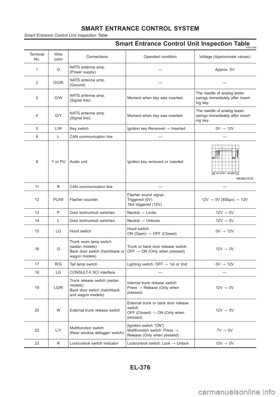
9 Y or PU Audio unit Ignition key removed or inserted
MKIB0191E
11 R CAN communication line — —
12 PU/W Flasher sounderFlasher sound signal :
Triggered (0V)
.Not triggered (12V)12V,0V (850μs),12V
13 P Door lock/unlock switches Neutral,Locks 12V,0V
14 L Door lock/unlock switches Neutral,Unlocks 12V,0V
15 LG Hood switchHood switch:
ON (Open),OFF (Closed)0V,12V
16 GTrunk room lamp switch
(sedan models)
Back door switch (hatchback or
wagon models)Trunk or back door release switch:
OFF,ON (Only when pressed)12V,0V
17 R/G Tail lamp switch Lighting switch: OFF,1st or 2nd 0V,12V
18 LG CONSULT-II SCI interface — —
19 LG/RTrunk release switch (sedan
models)
Back door switch (hatchback
and wagon models)Internal trunk release switch:
Press,Release (Only when
pressed)12V,0V
20 W External trunk release switchExternal trunk or back door release
switch:
OFF (Closed),ON (Only when
pressed)12V,0V
22 L/YMultifunction switch
(Rear window defogger switch)[Ignition switch “ON”]
Multifunction switch: Press,
Release (Only when pressed)7V,0V
23 R Lock/unlock switch indicator Lock/unlock switch: Lock,Unlock 12V,0V
SMART ENTRANCE CONTROL SYSTEM
Smart Entrance Control Unit Inspection Table
EL-376
Page 2772 of 3189
The Function of Each Icon Is as Follows:
Icon Description
AudioSound quality can be adjusted, and also ON/OFF setting of switch beep soundcan be performed.
Noise Compensation ON/OFF setting can be performed.
Display Settings of display can be performed.
LanguageLanguage can be selected for the display and voice guidance.
Use the program CD-ROM disc to change the language.
Navigation Settings and adjusting of navigation can be performed.
Navigation Expert Mode Easy Mode and Expert Mode can be switched.
Guidance Volume The volume and/or on/off of voice prompt can be controlledby the joystick.
Help Explanation of Navigational Functions Appear on the Display.
SKIA1399E
“LANGUAGE” modeNJEL0592S0804Select one of the languages which appear on the screen.
NOTE:
Languages that do not appear on the screen must be loaded from
program disk.
SKIA1385E
Navigation SettingsNJEL0592S0805How To Perform Navigation Settings
1. Start the engine.
2. Push “SETTING” switch.
3. Select “NAVIGATION”.
Application Items
Icon DescriptionReference
page
View Map display mode can be switched. EL-437
HeadingHeading of the map display can be customized for either north heading or
the actual driving direction of the vehicle.EL-437
Nearby Display IconsIcons of facilities can be displayed.
Facilities to be displayed can be selected from the variety selections.EL-437
Save Current Location Current vehicle location can be registered in Address Book. EL-438
NAVIGATION SYSTEM
System Description (Cont’d)
EL-436
Page 2794 of 3189
YEL832D
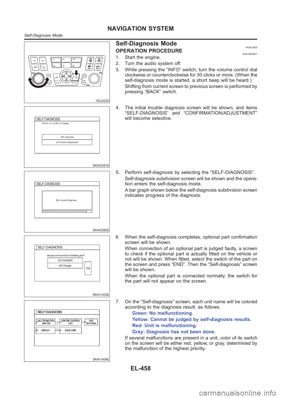
Self-Diagnosis Mode=NJEL0603OPERATION PROCEDURENJEL0603S011. Start the engine.
2. Turn the audio system off.
3. While pressing the “INFO” switch, turn the volume control dial
clockwise or counterclockwise for 30 clicks or more. (When the
self-diagnosis mode is started, a short beep will be heard.)
Shifting from current screen to previous screen is performed by
pressing “BACK” switch.
SKIA0381E
4. The initial trouble diagnosis screen will be shown, and items
“SELF-DIAGNOSIS” and “CONFIRMATION/ADJUSTMENT”
will become selective.
SKIA0382E
5. Perform self-diagnosis by selecting the “SELF-DIAGNOSIS”.
Self-diagnosis subdivision screen will be shown and the opera-
tion enters the self-diagnosis mode.
A bar graph shown below the self-diagnosis subdivision screen
indicates progress of the diagnosis.
SKIA1403E
6. When the self-diagnosis completes, optional part confirmation
screen will be shown.
When connection of an optional part is judged faulty, a screen
to check if the optional part is actually fitted on the vehicle or
not will be shown. When fitted, select the switch of the part on
the screen and press “END”. Then the “Self-diagnosis” screen
will be shown.
When the optional part is connected normally, the switch for
the part will not appear on the screen.
SKIA1404E
7. On the “Self-diagnosis” screen, each unit name will be colored
according to the diagnosis result, as follows.
Green: No malfunctioning.
Yellow: Cannot be judged by self-diagnosis results.
Red: Unit is malfunctioning.
Gray: Diagnosis has not been done.
If several malfunctions are present in a unit, color of its switch
on the screen will be either red, yellow, or gray, determined by
the malfunction of the highest priority.
NAVIGATION SYSTEM
Self-Diagnosis Mode
EL-458
Page 2796 of 3189
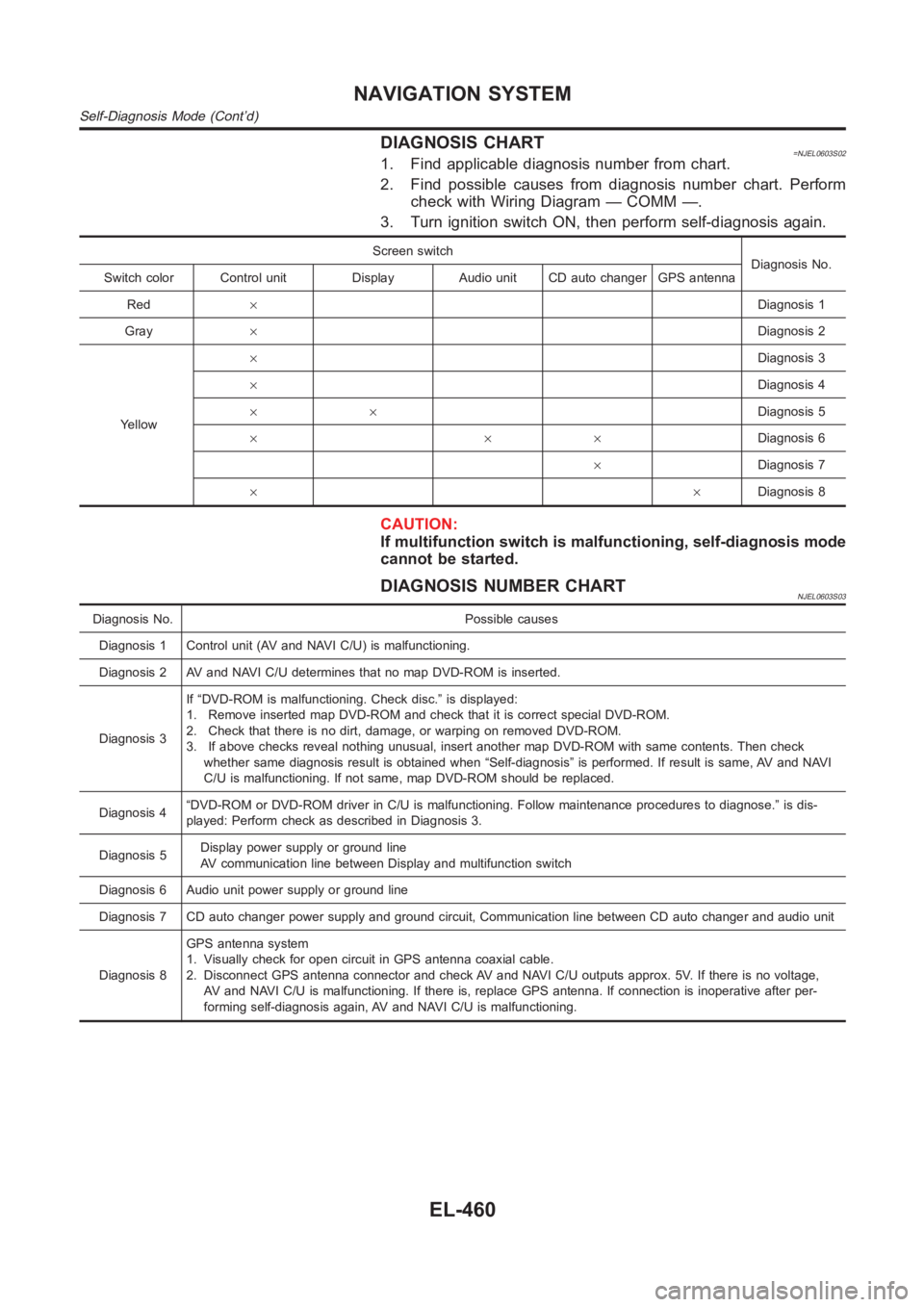
DIAGNOSIS CHART=NJEL0603S021. Find applicable diagnosis number from chart.
2. Find possible causes from diagnosis number chart. Perform
check with Wiring Diagram — COMM —.
3. Turn ignition switch ON, then perform self-diagnosis again.
Screen switch
Diagnosis No.
Switch color Control unit Display Audio unit CD auto changer GPS antenna
Red×Diagnosis 1
Gray×Diagnosis 2
Yellow×Diagnosis 3
×Diagnosis 4
××Diagnosis 5
×××Diagnosis 6
×Diagnosis 7
××Diagnosis 8
CAUTION:
If multifunction switch is malfunctioning, self-diagnosis mode
cannot be started.
DIAGNOSIS NUMBER CHARTNJEL0603S03
Diagnosis No. Possible causes
Diagnosis 1 Control unit (AV and NAVI C/U) is malfunctioning.
Diagnosis 2 AV and NAVI C/U determines that no map DVD-ROM is inserted.
Diagnosis 3If “DVD-ROM is malfunctioning. Check disc.” is displayed:
1. Remove inserted map DVD-ROM and check that it is correct special DVD-ROM.
2. Check that there is no dirt, damage, or warping on removed DVD-ROM.
3. If above checks reveal nothing unusual, insert another map DVD-ROM withsame contents. Then check
whether same diagnosis result is obtained when “Self-diagnosis” is performed. If result is same, AV and NAVI
C/U is malfunctioning. If not same, map DVD-ROM should be replaced.
Diagnosis 4“DVD-ROM or DVD-ROM driver in C/U is malfunctioning. Follow maintenance procedures to diagnose.” is dis-
played: Perform check as described in Diagnosis 3.
Diagnosis 5Display power supply or ground line
AV communication line between Display and multifunction switch
Diagnosis 6 Audio unit power supply or ground line
Diagnosis 7 CD auto changer power supply and ground circuit, Communication line between CD auto changer and audio unit
Diagnosis 8GPS antenna system
1. Visually check for open circuit in GPS antenna coaxial cable.
2. Disconnect GPS antenna connector and check AV and NAVI C/U outputs approx. 5V. If there is no voltage,
AV and NAVI C/U is malfunctioning. If there is, replace GPS antenna. If connection is inoperative after per-
forming self-diagnosis again, AV and NAVI C/U is malfunctioning.
NAVIGATION SYSTEM
Self-Diagnosis Mode (Cont’d)
EL-460
Page 2797 of 3189
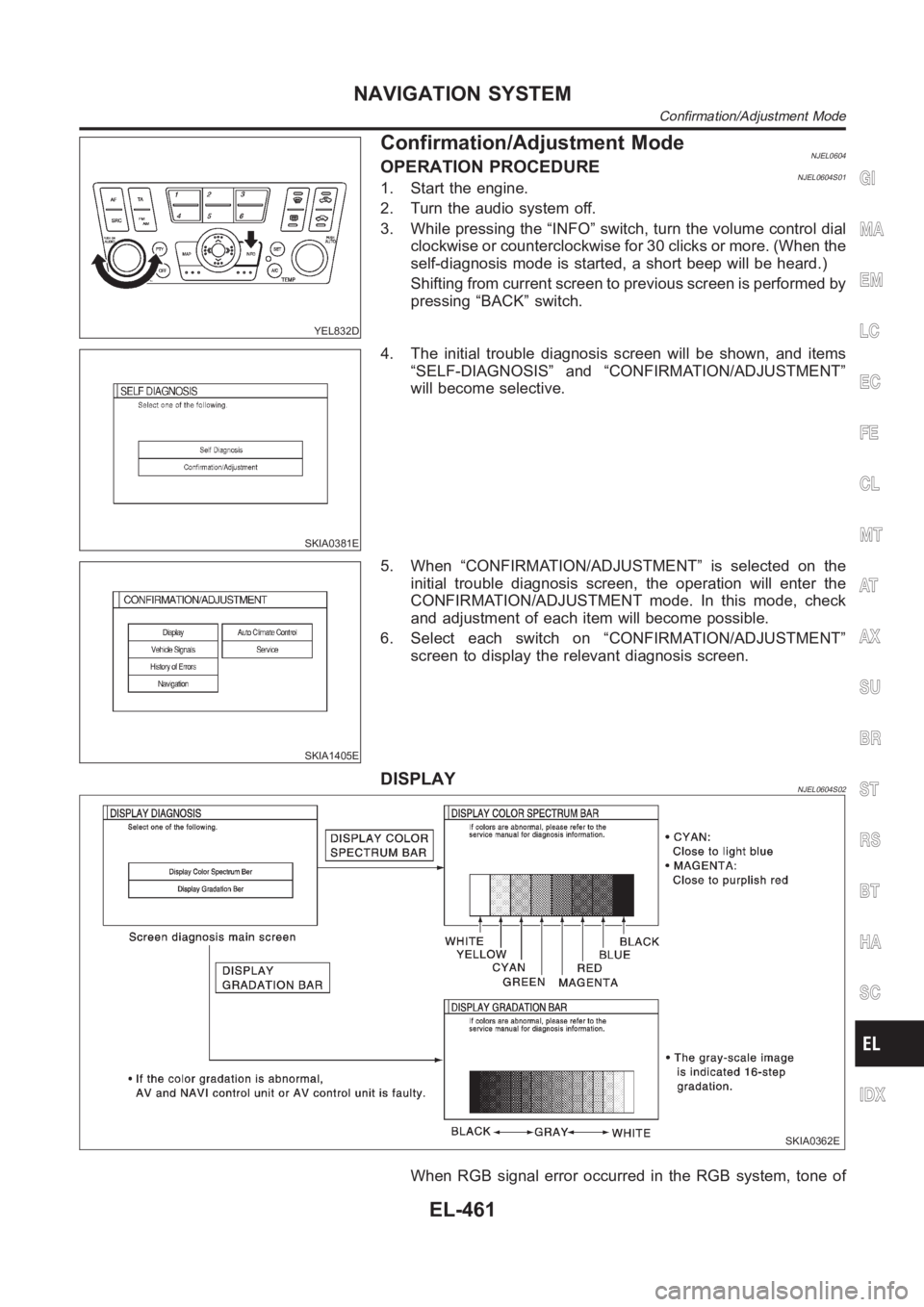
YEL832D
Confirmation/Adjustment ModeNJEL0604OPERATION PROCEDURENJEL0604S011. Start the engine.
2. Turn the audio system off.
3. While pressing the “INFO” switch, turn the volume control dial
clockwise or counterclockwise for 30 clicks or more. (When the
self-diagnosis mode is started, a short beep will be heard.)
Shifting from current screen to previous screen is performed by
pressing “BACK” switch.
SKIA0381E
4. The initial trouble diagnosis screen will be shown, and items
“SELF-DIAGNOSIS” and “CONFIRMATION/ADJUSTMENT”
will become selective.
SKIA1405E
5. When “CONFIRMATION/ADJUSTMENT” is selected on the
initial trouble diagnosis screen, the operation will enter the
CONFIRMATION/ADJUSTMENT mode. In this mode, check
and adjustment of each item will become possible.
6. Select each switch on “CONFIRMATION/ADJUSTMENT”
screen to display the relevant diagnosis screen.
DISPLAYNJEL0604S02
SKIA0362E
When RGB signal error occurred in the RGB system, tone of
GI
MA
EM
LC
EC
FE
CL
MT
AT
AX
SU
BR
ST
RS
BT
HA
SC
IDX
NAVIGATION SYSTEM
Confirmation/Adjustment Mode
EL-461
Page 2813 of 3189
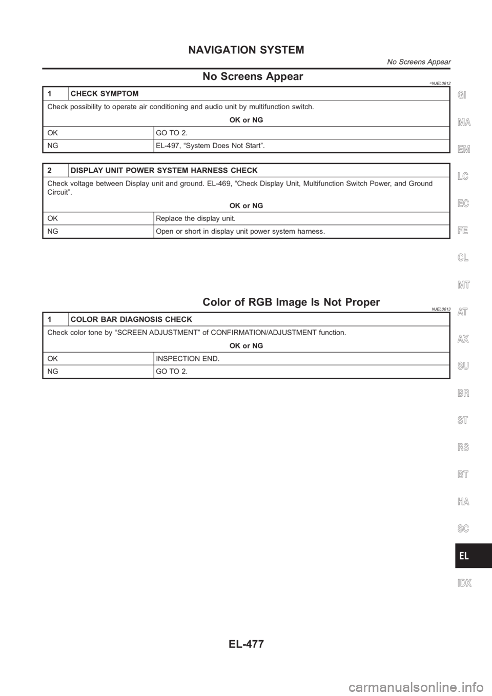
No Screens Appear=NJEL0612
1 CHECK SYMPTOM
Check possibility to operate air conditioning and audio unit by multifunction switch.
OK or NG
OK GO TO 2.
NG EL-497, “System Does Not Start”.
2 DISPLAY UNIT POWER SYSTEM HARNESS CHECK
Check voltage between Display unit and ground. EL-469, “Check Display Unit, Multifunction Switch Power, and Ground
Circuit”.
OK or NG
OK Replace the display unit.
NG Open or short in display unit power system harness.
Color of RGB Image Is Not ProperNJEL0613
1 COLOR BAR DIAGNOSIS CHECK
Check color tone by “SCREEN ADJUSTMENT” of CONFIRMATION/ADJUSTMENT function.
OK or NG
OK INSPECTION END.
NG GO TO 2.
GI
MA
EM
LC
EC
FE
CL
MT
AT
AX
SU
BR
ST
RS
BT
HA
SC
IDX
NAVIGATION SYSTEM
No Screens Appear
EL-477
Page 2820 of 3189
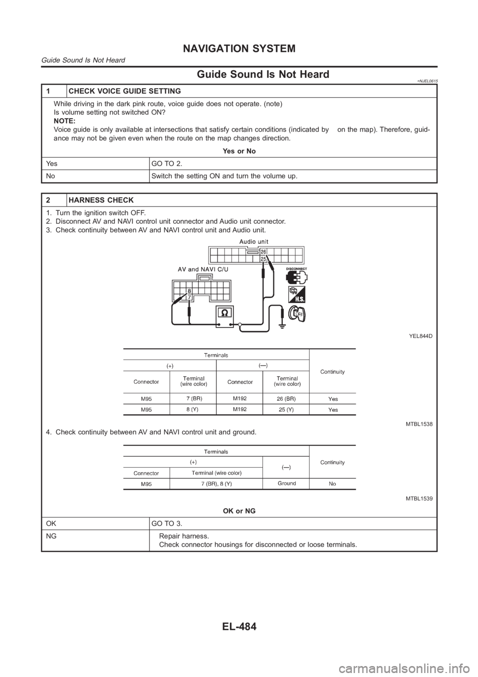
Guide Sound Is Not Heard=NJEL0615
1 CHECK VOICE GUIDE SETTING
While driving in the dark pink route, voice guide does not operate. (note)
Is volume setting not switched ON?
NOTE:
Voice guide is only available at intersections that satisfy certain conditions (indicated by on the map). Therefore, guid-
ance may not be given even when the route on the map changes direction.
YesorNo
Ye s G O T O 2 .
No Switch the setting ON and turn the volume up.
2 HARNESS CHECK
1. Turn the ignition switch OFF.
2. Disconnect AV and NAVI control unit connector and Audio unit connector.
3. Check continuity between AV and NAVI control unit and Audio unit.
YEL844D
MTBL1538
4. Check continuity between AV and NAVI control unit and ground.
MTBL1539
OK or NG
OK GO TO 3.
NG Repair harness.
Check connector housings for disconnected or loose terminals.
NAVIGATION SYSTEM
Guide Sound Is Not Heard
EL-484