2003 NISSAN ALMERA N16 AUX
[x] Cancel search: AUXPage 54 of 3189
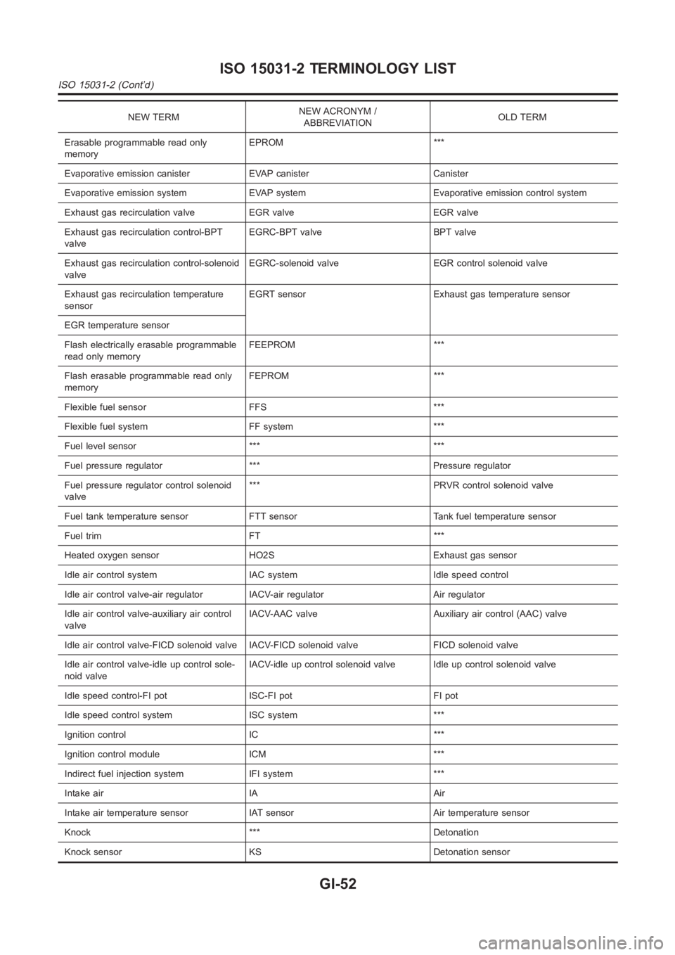
NEW TERMNEW ACRONYM /
ABBREVIATIONOLD TERM
Erasable programmable read only
memoryEPROM ***
Evaporative emission canister EVAP canister Canister
Evaporative emission system EVAP system Evaporative emission control system
Exhaust gas recirculation valve EGR valve EGR valve
Exhaust gas recirculation control-BPT
valveEGRC-BPT valve BPT valve
Exhaust gas recirculation control-solenoid
valveEGRC-solenoid valve EGR control solenoid valve
Exhaust gas recirculation temperature
sensorEGRT sensor Exhaust gas temperature sensor
EGR temperature sensor
Flash electrically erasable programmable
read only memoryFEEPROM ***
Flash erasable programmable read only
memoryFEPROM ***
Flexible fuel sensor FFS ***
Flexible fuel system FF system ***
Fuel level sensor *** ***
Fuel pressure regulator *** Pressure regulator
Fuel pressure regulator control solenoid
valve*** PRVR control solenoid valve
Fuel tank temperature sensor FTT sensor Tank fuel temperature sensor
Fuel trim FT ***
Heated oxygen sensor HO2S Exhaust gas sensor
Idle air control system IAC system Idle speed control
Idle air control valve-air regulator IACV-air regulator Air regulator
Idle air control valve-auxiliary air control
valveIACV-AAC valve Auxiliary air control (AAC) valve
Idle air control valve-FICD solenoid valve IACV-FICD solenoid valve FICDsolenoid valve
Idle air control valve-idle up control sole-
noid valveIACV-idle up control solenoid valve Idle up control solenoid valve
Idle speed control-FI pot ISC-FI pot FI pot
Idle speed control system ISC system ***
Ignition control IC ***
Ignition control module ICM ***
Indirect fuel injection system IFI system ***
Intake air IA Air
Intake air temperature sensor IAT sensor Air temperature sensor
Knock *** Detonation
Knock sensor KS Detonation sensor
ISO 15031-2 TERMINOLOGY LIST
ISO 15031-2 (Cont’d)
GI-52
Page 125 of 3189
![NISSAN ALMERA N16 2003 Electronic Repair Manual TIMING CHAIN
EM-47
[QG]
C
D
E
F
G
H
I
J
K
L
MA
EM
TIMING CHAINPFP:13028
Removal and InstallationEBS00LQD
CAUTION:
Apply new engine oil to parts marked in illustration before installation.
REMOVAL
1. P](/manual-img/5/57350/w960_57350-124.png "NISSAN ALMERA N16 2003 Electronic Repair Manual TIMING CHAIN
EM-47
[QG]
C
D
E
F
G
H
I
J
K
L
MA
EM
TIMING CHAINPFP:13028
Removal and InstallationEBS00LQD
CAUTION:
Apply new engine oil to parts marked in illustration before installation.
REMOVAL
1. P")
TIMING CHAIN
EM-47
[QG]
C
D
E
F
G
H
I
J
K
L
MA
EM
TIMING CHAINPFP:13028
Removal and InstallationEBS00LQD
CAUTION:
Apply new engine oil to parts marked in illustration before installation.
REMOVAL
1. Place vehicle on lift.
PBIC0971E
1. Cylinder head front cover 2. Camshaft sprocket (INT) 3. Washer
4. Camshaft sprocket (EXH) 5. Chain tensioner 6. Chain slack guide
7. O-ring 8. Power steering pump adjusting bar 9. Crankshaft pulley
10. Front oil seal 11. Front cover 12. Chain tension guide
13. Dowel pin 14. Timing chain 15. Oil pump drive spacer
16. Crankshaft sprocket 17. O-ring (with collar) 18. Auxiliary bolt of cylinder head
Page 126 of 3189
![NISSAN ALMERA N16 2003 Electronic Repair Manual EM-48
[QG]
TIMING CHAIN
2. Disconnect battery ground cable.
3. Remove undercover, front RH wheel and RH splash cover.
4. Drain engine coolant from radiator and cylinder block. Refer to LC-17, "Cha](/manual-img/5/57350/w960_57350-125.png "NISSAN ALMERA N16 2003 Electronic Repair Manual EM-48
[QG]
TIMING CHAIN
2. Disconnect battery ground cable.
3. Remove undercover, front RH wheel and RH splash cover.
4. Drain engine coolant from radiator and cylinder block. Refer to LC-17, \"Cha")
EM-48
[QG]
TIMING CHAIN
2. Disconnect battery ground cable.
3. Remove undercover, front RH wheel and RH splash cover.
4. Drain engine coolant from radiator and cylinder block. Refer to LC-17, "Changing Engine Coolant".
5. Drain engine oil from oil pan.
6. Remove drive belt. Refer to EM-13, "
Removal and Installation" .
7. Remove power steering pump from adjusting bar.
8. Remove alternator. SC-33, "Removal and Installation".
9. Remove ignition coils. Refer to EM-24, "
IGNITION COIL" .
10. Remove rocker cover. Refer to EM-29, "
Removal and Installation" .
11. Remove oil level gauge.
12. Remove exhaust front tube. Refer to FE-10, "Removal and Installation".
13. Remove center member.
14. Remove gusset.
15. Remove rear plate (lower) (A/T models).
16. Remove oil pan and oil strainer. Refer to EM-22, "
Removal and Installation" .
17. For safe operation, and to reduce load to mount insulator, install removed center member again.
18. Remove engine front-side (right side of vehicle) engine mount. Refer to EM-67, "
ENGINE ASSEMBLY" .
a. Remove any parts that cause difficulties for operation around mount, or perform transfer.
b. Support cylinder block bottom surface with a transmission jack.
CAUTION:
●When applying jack, use a wooden block to avoid damage to oil pan mounting surface.
●While performing following operations, support engine front-side with jack.
c. Separate engine mounting insulator and bracket.
d. Remove engine mounting bracket.
19. Remove cylinder head front cover.
●Move harness which was previously fixed on front surface.
20. Remove auxiliary bolts of cylinder head.
21. Set the No. 1 cylinder to the compression TDC.
a. Turn the crankshaft pulley clockwise, and align the timing indica-
tor of the gear case to the timing mark of the crankshaft pulley.
PBIC0557E
PBIC0750E
Page 131 of 3189
![NISSAN ALMERA N16 2003 Electronic Repair Manual TIMING CHAIN
EM-53
[QG]
C
D
E
F
G
H
I
J
K
L
MA
EM
h. Install front cover with mounting bolts temporarily so that front
cover will not move.
i. Press fit dowel pin into cylinder block through](/manual-img/5/57350/w960_57350-130.png "NISSAN ALMERA N16 2003 Electronic Repair Manual TIMING CHAIN
EM-53
[QG]
C
D
E
F
G
H
I
J
K
L
MA
EM
h. Install front cover with mounting bolts temporarily so that front
cover will not move.
i. Press fit dowel pin into cylinder block through")
TIMING CHAIN
EM-53
[QG]
C
D
E
F
G
H
I
J
K
L
MA
EM
h. Install front cover with mounting bolts temporarily so that front
cover will not move.
i. Press fit dowel pin into cylinder block through front cover.
j. Tighten front cover mounting bolts temporarily.
●A [M6 x 20 mm (0.79 in)], B [M6 x 40 mm (1.57 in)], C [M8 x
70 mm (2.76 in)], D [M6 x 73 mm (2.87 in)]
●Bolt C also secures power steering pump adjusting bar.
●Bolt E [M6 x 12 mm (0.47 in)] is for installing power steering
pump adjusting bar.
k. Tighten cylinder head auxiliary bolts (M6) temporarily.
l. Tighten front cover mounting bolts and cylinder head auxiliary
bolts to specified torque.
4. Install oil pump drive spacer.
●When installing, align with flat of oil pump inner rotor.
●If they are not aligned, rotate inner rotor with a flat-bladed
screwdriver to align them.
CAUTION:
Be careful not to damage oil seal lips.
5. Install water pump pulley and idler pulley bracket assembly.
6. Install crankshaft pulley.
●When installing it, make sure that front oil seal lip is not inverted and garter spring is in position.
●For direction of mounting bolt washer, refer to “Component Parts Location”.
●With same procedure as “removal”, secure crankshaft, and tighten mounting bolts.
7. Install cylinder head front cover.
●Apply liquid gasket to cylinder head front cover.
●Use Genuine Liquid Gasket or equivalent.
8. Install engine front mounting bracket.
9. Install remaining parts in the reverse order of removal.
INSPECTION AFTER INSTALLATION
●In order to allow liquid gasket to be cured, perform inspection at least 30 minutes after the last step in
which parts sealed with liquid gasket are installed.
●With engine warmed up, check each part for engine oil leakage.
PBIC0564E
EMD0850D
PBIC0566E
PBIC0968E
Page 136 of 3189
![NISSAN ALMERA N16 2003 Electronic Repair Manual EM-58
[QG]
CYLINDER HEAD
8. Install spark plug, ignition coil and harness connectors.
Removal and InstallationEBS00LQI
REMOVAL
1. Release fuel pressure. Refer to EC-34, "FUEL PRESSURE RELEA](/manual-img/5/57350/w960_57350-135.png "NISSAN ALMERA N16 2003 Electronic Repair Manual EM-58
[QG]
CYLINDER HEAD
8. Install spark plug, ignition coil and harness connectors.
Removal and InstallationEBS00LQI
REMOVAL
1. Release fuel pressure. Refer to EC-34, \"FUEL PRESSURE RELEA")
EM-58
[QG]
CYLINDER HEAD
8. Install spark plug, ignition coil and harness connectors.
Removal and InstallationEBS00LQI
REMOVAL
1. Release fuel pressure. Refer to EC-34, "FUEL PRESSURE RELEASE" (WITH EURO-OBD), EC-427,
"FUEL PRESSURE RELEASE" (WITHOUT EURO-OBD).
2. Remove undercover.
3. Drain engine coolant. Refer to LC-17, "Changing Engine Coolant".
4. Remove the following components and related parts:
●Intake manifold and intake manifold collector. Refer to EM-16, "INTAKE MANIFOLD" .
●Exhaust manifold and catalytic converter. Refer to EM-19, "EXHAUST MANIFOLD AND CATALYTIC
CONVERTER" .
●Ignition coil. Refer to EM-24, "IGNITION COIL" .
●Rocker cover. Refer to EM-29, "ROCKER COVER" .
●Camshaft. Refer to EM-32, "CAMSHAFT" .
●Alternator bracket. Refer to SC-33, "Removal and Installation".
PBIC0972E
1. Rear engine slinger 2. Cylinder head bolt 3. Washer
4. Auxiliary bolt of cylinder head 5. Cylinder head gasket 6. Cylinder head assembly
Page 138 of 3189
![NISSAN ALMERA N16 2003 Electronic Repair Manual EM-60
[QG]
CYLINDER HEAD
3. Tighten cylinder auxiliary bolts (11) to (14) in numerical order
shown in figure.
●Pay attention to shank length under bolt head. [11: 20 mm
(0.79 in), 12 - 14:](/manual-img/5/57350/w960_57350-137.png "NISSAN ALMERA N16 2003 Electronic Repair Manual EM-60
[QG]
CYLINDER HEAD
3. Tighten cylinder auxiliary bolts (11) to (14) in numerical order
shown in figure.
●Pay attention to shank length under bolt head. [11: 20 mm
(0.79 in), 12 - 14:")
EM-60
[QG]
CYLINDER HEAD
3. Tighten cylinder auxiliary bolts (11) to (14) in numerical order
shown in figure.
●Pay attention to shank length under bolt head. [11: 20 mm
(0.79 in), 12 - 14: 25 mm (0.98 in)]
Disassembly and AssemblyEBS00LQJ
CAUTION:
●When installing camshafts, chain tensioners, oil seals or other sliding parts, lubricate contacting
surface with new engine oil.
●Apply new engine oil to threads and seat surface when installing cylinder head, camshaft
sprocket, crankshaft pulley and camshaft bracket.
●Attach tags to valve lifters so as not to mix them up.
DISASSEMBLY
1. Remove adjusting shim (if so equipped) and valve lifter.
●Confirm installation point.
SEM900F
PBIC0973E
1. Cylinder head 2. Valve (INT) 3. Valve (EXH)
4. Valve seat 5. Engine coolant temperature sensor 6. Copper washer
7. Spark plug tube 8. Spark plug
Page 150 of 3189
![NISSAN ALMERA N16 2003 Electronic Repair Manual EM-72
[QG]
CYLINDER BLOCK
●A commercial engine stand can be used.
NOTE:
●This example is an engine stand for holding at transaxle
mounting side with the flywheel or drive plate removed.
3](/manual-img/5/57350/w960_57350-149.png "NISSAN ALMERA N16 2003 Electronic Repair Manual EM-72
[QG]
CYLINDER BLOCK
●A commercial engine stand can be used.
NOTE:
●This example is an engine stand for holding at transaxle
mounting side with the flywheel or drive plate removed.
3")
EM-72
[QG]
CYLINDER BLOCK
●A commercial engine stand can be used.
NOTE:
●This example is an engine stand for holding at transaxle
mounting side with the flywheel or drive plate removed.
3. Drain engine oil and coolant from inside of engine.
4. Remove the following components and associated parts.
●Fuel tube and injector assembly; Refer to EM-26, "Removal and Installation" .
●Intake manifold and intake manifold collector assembly; Refer to EM-16, "Removal and Installation" .
●Ignition coil; Refer to EM-24, "Removal and Installation" .
●Rocker cover; Refer to EM-29, "Removal and Installation" .
●Oil pan and oil strainer; Refer to EM-22, "Removal and Installation" .
●Front cover and timing chain; Refer to EM-47, "Removal and Installation" .
●Camshaft; Refer to EM-32, "Removal and Installation" .
●Cylinder head assembly; Refer to EM-58, "Removal and Installation" .
●Auxiliary brackets and oil filter
5. Remove knock sensor.
CAUTION:
Avoid impacts such as a dropping.
6. Remove crankshaft position sensor (POS).
CAUTION:
●Avoid impacts such as a dropping.
●Do not disassemble.
●Keep it away from metal particles.
●Do not place sensor close to magnetic materials.
7. Remove flywheel (M/T models) or drive plate (A/T models). Fix
crankshaft with a ring gear stopper (special service tool), and
remove mounting bolts.
8. Remove rear plate.
9. Remove rear oil seal retainer.
●Insert a flat-bladed screwdriver between main bearing cap
and rear oil seal retainer to remove retainer.
10. Remove rear oil seal from rear oil seal retainer.
●Punch out with a flat-bladed screwdriver.
CAUTION:
●Be careful not to damage rear oil seal retainer.
PBIC0085E
PBIC0586E
SEM880F
Page 248 of 3189

crankshaft position sensor (TDC sensor) from the assem-
bly.
Always pay extra attention not to damage edge of crank-
shaft position sensor (TDC sensor) or ring gear teeth.
REMOVALNJEM0069S011. Remove engine undercover, and hood for hoisting.
2. Drain coolant from both cylinder block and radiator. Refer to
LC-43, “Changing Engine Coolant”.
3. Remove the following parts:
Battery
RH and LH front wheels
RH and LH splash covers (combined with undercover)
Auxiliary belts
Alternator
Alternator brackets
Radiator and cooling fan
Engine cover
Air ducts and air cleaner case
LH side of engine room:
4. Disconnect all harnesses and grounds that are connected to
components on vehicle.
5. Disconnect vacuum hose on vacuum pump side.
6. Disconnect fuel feed and fuel return hoses on engine side.
Immediately put blind plugs into the openings to prevent
fuel from flowing out.
7. Disconnect heater hose. Plug opening of hose to prevent cool-
ant from flowing out.
RH side of engine room:
8. Remove air conditioner compressor from brackets and move
it toward vehicle side. Secure compressor on vehicle side with
rope.
Vehicle underside:
9. Remove exhaust front tube.
10. Disconnect two hoses from power steering pump and plug to
stop fluid.
11. Remove M/T control rod and support rod.
12. Remove ABS wheel sensor, and temporarily hang brake cali-
per with rope on vehicle side.
13. Remove RH and LH drive shafts.
YEM024
14. Install engine slingers to cylinder head.
: 30 - 37 N·m (3.0 - 3.8 kg-m, 22 - 27 ft-lb)
Use engine slingers and securing bolts of the specified
service parts.
15. Lift up vehicle to appropriate level where work can be per-
formed efficiently. Using two transmission jacks, securely sup-
port engine oil pan and bottom surface of transaxle.
ENGINE ASSEMBLYYD
Removal and Installation (Cont’d)
EM-64