2003 NISSAN ALMERA N16 driver lock
[x] Cancel search: driver lockPage 122 of 3189
![NISSAN ALMERA N16 2003 Electronic Repair Manual EM-44
[QG]
CAMSHAFT
●Thickness of a new valve lifter can be identified by stamp
marks on the reverse side (inside the cylinder).
Stamp mark 696 indicates 6.96 mm (0.2740 in) in thickness.](/manual-img/5/57350/w960_57350-121.png "NISSAN ALMERA N16 2003 Electronic Repair Manual EM-44
[QG]
CAMSHAFT
●Thickness of a new valve lifter can be identified by stamp
marks on the reverse side (inside the cylinder).
Stamp mark 696 indicates 6.96 mm (0.2740 in) in thickness.")
EM-44
[QG]
CAMSHAFT
●Thickness of a new valve lifter can be identified by stamp
marks on the reverse side (inside the cylinder).
Stamp mark 696 indicates 6.96 mm (0.2740 in) in thickness.
Available thickness of valve lifter: 26 sizes with range 6.96 to 7.46 mm (0.2740 to 0.2937 in) in steps of 0.02
mm (0.0008 in) (when manufactured at factory).
5. Install the selected valve lifter.
6. Install camshaft.
7. Manually turn crankshaft pulley a few turns.
8. Check that valve clearances for cold engine are within specifications by referring to the specified values.
9. After completing the repair, check valve clearances again with the specifications for warmed engine. Make
sure the values are within specifications.
Valve clearance:
Unit: mm (in)
*: Approximately 20°C (68°F)
ADJUSTMENT (SHIM TYPE)
●Remove adjusting shim for valves with incorrect valve clearance by following the procedure below:
1. Using a rag, completely wipe off engine oil from surroundings of adjusting shim.
2. When removing adjusting shim from a cam, turn crankshaft
clockwise (viewed from front) to make cam nose face straight
up.
3. Turn valve lifter and adjusting shim to removal direction.
●Using a slotted screwdriver with extra-thin tip, turn valve lifter
cutout in direction shown by the arrow.
4. Using camshaft pliers (special service tool), pinch camshaft.
Turn tool up in direction shown by the arrow with camshaft being
a fulcrum. This will push down adjusting shim to allow valve
spring to be compressed.
CAUTION:
●Be careful not to damage camshaft and cylinder head.
●Be careful not to damage surroundings of valve lifter.
PBIC1077E
Cold* (reference data) Hot
Intake 0.24 - 0.32 (0.009 - 0.013) 0.32 - 0.40 (0.013 - 0.016)
Exhaust 0.26 - 0.34 (0.010 - 0.013) 0.33 - 0.41 (0.013 - 0.016)
MBIB0226E
KBIA1391J
Page 128 of 3189
![NISSAN ALMERA N16 2003 Electronic Repair Manual EM-50
[QG]
TIMING CHAIN
24. Remove front cover with the following procedure:
a. To increase freedom of front cover posture during removal/
installation, pull oil pump drive spacer out through](/manual-img/5/57350/w960_57350-127.png "NISSAN ALMERA N16 2003 Electronic Repair Manual EM-50
[QG]
TIMING CHAIN
24. Remove front cover with the following procedure:
a. To increase freedom of front cover posture during removal/
installation, pull oil pump drive spacer out through")
EM-50
[QG]
TIMING CHAIN
24. Remove front cover with the following procedure:
a. To increase freedom of front cover posture during removal/
installation, pull oil pump drive spacer out through front oil seal.
●Pull it straight out using long-nose priers or two flat-bladed
screwdrivers.
CAUTION:
Be careful not to damage side of oil pump drive spacer and
front oil seal lip.
b. Remove power steering pump adjusting bar.
c. Remove front cover carefully.
●Remove mounting bolts A - E shown in figure.
NOTE:
Bolts C and E have been removed in step b.
CAUTION:
●When removing, be careful not to damage or bend front
end of cylinder head gasket. Also after peeling off con-
tact face between front cover and gasket, their surfaces
shall be smooth.
●If cylinder head gasket is damaged, replace it with new
one.
d. Remove O-rings from front cover and cylinder block.
25. Pull two dowel pins for front cover out of cylinder block.
●Heat them with industrial dryer sufficiently, then pull them out
using locking pliers.
NOTE:
This operation is performed as preparation operation for front
cover installation. This operation can be performed after
removal of timing chain.
26. If front oil seal is need to be replaced, remove it from front cover.
●Insert a flat-bladed screwdriver in notch on oil seal mounting
point, and lift oil seal to remove.
NOTE:
Remove timing chain and its related parts with the following pro-
cedure:
27. Secure intake camshaft sprocket in most advanced position. Refer to EM-32, "
REMOVAL" .
NOTE:
Removal of timing chain and related parts is described in following steps.
28. Remove chain tensioner. Refer to EM-32, "
REMOVAL" .
29. Remove camshaft sprocket. Refer to EM-32, "
REMOVAL" .
CAUTION:
After this step is completed, do not rotate crankshaft and camshaft separately in order to prevent
interference between valve and piston.
PBIC0566E
EMD0850D
PBIC0567E
PBIC0558E
Page 130 of 3189
![NISSAN ALMERA N16 2003 Electronic Repair Manual EM-52
[QG]
TIMING CHAIN
2. Install front oil seal to front cover.
●Install it so that identification letters on oil seal will face toward
front side of the engine.
●Using an oil seal drift (commer](/manual-img/5/57350/w960_57350-129.png "NISSAN ALMERA N16 2003 Electronic Repair Manual EM-52
[QG]
TIMING CHAIN
2. Install front oil seal to front cover.
●Install it so that identification letters on oil seal will face toward
front side of the engine.
●Using an oil seal drift (commer")
EM-52
[QG]
TIMING CHAIN
2. Install front oil seal to front cover.
●Install it so that identification letters on oil seal will face toward
front side of the engine.
●Using an oil seal drift (commercial service tool), press oil seal
in until it is flush with end surface of mounting position.
●Make sure that oil seal outer circumference is free from dam-
age and burr.
3. Install front cover with the following procedure:
a. Install O-ring to cylinder block.
b. Using a flat-bladed screwdriver, apply a continuous bead of liq-
uid gasket to contact surface between cylinder head gasket
lower surface and cylinder block (2 locations shown in figure).
Use Genuine Liquid Gasket or equivalent.
c. Apply a continuous bead of liquid gasket to back surface of front
cover (location shown in figure).
CAUTION:
●Do not apply liquid gasket to groove A shown in figure.
●Especially for locations indicated by * mark in figure,
strictly observe application range of liquid gasket.
d. Apply liquid gasket to top surface of front cover lightly and
evenly.
Use Genuine Liquid Gasket or equivalent.
e. Install O-ring to back surface of front cover.
f. With socket of oil pump inner rotor placed on crankshaft top sur-
face (clearance between front cover top surface and cylinder
head gasket lower surface is secured), move front cover close to
cylinder block. (Right side in figure)
g. Lift front cover at an angle and install it to mounting position so
that front cover will come in contact with both cylinder head gas-
ket lower surface and cylinder block front surface at the same
time. (Right side in figure)
CAUTION:
●During work, be sure not to damage cylinder head gas-
ket.
●When installing, avoid discontinuous bead of liquid gas-
ket caused by allowing it to adhere to an unnecessary area.
PBIC0530E
PBIC0561E
PBIC0562E
PBIC0563E
Page 131 of 3189
![NISSAN ALMERA N16 2003 Electronic Repair Manual TIMING CHAIN
EM-53
[QG]
C
D
E
F
G
H
I
J
K
L
MA
EM
h. Install front cover with mounting bolts temporarily so that front
cover will not move.
i. Press fit dowel pin into cylinder block through](/manual-img/5/57350/w960_57350-130.png "NISSAN ALMERA N16 2003 Electronic Repair Manual TIMING CHAIN
EM-53
[QG]
C
D
E
F
G
H
I
J
K
L
MA
EM
h. Install front cover with mounting bolts temporarily so that front
cover will not move.
i. Press fit dowel pin into cylinder block through")
TIMING CHAIN
EM-53
[QG]
C
D
E
F
G
H
I
J
K
L
MA
EM
h. Install front cover with mounting bolts temporarily so that front
cover will not move.
i. Press fit dowel pin into cylinder block through front cover.
j. Tighten front cover mounting bolts temporarily.
●A [M6 x 20 mm (0.79 in)], B [M6 x 40 mm (1.57 in)], C [M8 x
70 mm (2.76 in)], D [M6 x 73 mm (2.87 in)]
●Bolt C also secures power steering pump adjusting bar.
●Bolt E [M6 x 12 mm (0.47 in)] is for installing power steering
pump adjusting bar.
k. Tighten cylinder head auxiliary bolts (M6) temporarily.
l. Tighten front cover mounting bolts and cylinder head auxiliary
bolts to specified torque.
4. Install oil pump drive spacer.
●When installing, align with flat of oil pump inner rotor.
●If they are not aligned, rotate inner rotor with a flat-bladed
screwdriver to align them.
CAUTION:
Be careful not to damage oil seal lips.
5. Install water pump pulley and idler pulley bracket assembly.
6. Install crankshaft pulley.
●When installing it, make sure that front oil seal lip is not inverted and garter spring is in position.
●For direction of mounting bolt washer, refer to “Component Parts Location”.
●With same procedure as “removal”, secure crankshaft, and tighten mounting bolts.
7. Install cylinder head front cover.
●Apply liquid gasket to cylinder head front cover.
●Use Genuine Liquid Gasket or equivalent.
8. Install engine front mounting bracket.
9. Install remaining parts in the reverse order of removal.
INSPECTION AFTER INSTALLATION
●In order to allow liquid gasket to be cured, perform inspection at least 30 minutes after the last step in
which parts sealed with liquid gasket are installed.
●With engine warmed up, check each part for engine oil leakage.
PBIC0564E
EMD0850D
PBIC0566E
PBIC0968E
Page 133 of 3189
![NISSAN ALMERA N16 2003 Electronic Repair Manual OIL SEAL
EM-55
[QG]
C
D
E
F
G
H
I
J
K
L
MA
EM
Removal and Installation of Front Oil SealEBS00LQF
REMOVAL
1. Remove the following parts:
●Undercover (with splash cover)
●Drive belt; Refer to EM-11,](/manual-img/5/57350/w960_57350-132.png "NISSAN ALMERA N16 2003 Electronic Repair Manual OIL SEAL
EM-55
[QG]
C
D
E
F
G
H
I
J
K
L
MA
EM
Removal and Installation of Front Oil SealEBS00LQF
REMOVAL
1. Remove the following parts:
●Undercover (with splash cover)
●Drive belt; Refer to EM-11,")
OIL SEAL
EM-55
[QG]
C
D
E
F
G
H
I
J
K
L
MA
EM
Removal and Installation of Front Oil SealEBS00LQF
REMOVAL
1. Remove the following parts:
●Undercover (with splash cover)
●Drive belt; Refer to EM-11, "DRIVE BELTS" .
●Crankshaft pulley; Refer to EM-47, "TIMING CHAIN" .
2. Using flat-head screwdriver, remove front oil seal.
CAUTION:
Be careful not to damage front timing chain cover and crankshaft.
INSTALLATION
1. Apply engine oil on new front oil seal.
2. Using a suitable drift, press fit until the height of front oil seal is
level with the mounting surface.
●Suitable drift : outer diameter 50 mm (1.97 in), inner diameter
44 mm (1.73 in).
CAUTION:
●Be careful not to damage front cover and crankshaft.
●Press oil seal straight so that it is not curling up or
inclined.
3. Perform steps in the reverse order of removal for the following
operations.
Removal and Installation of Rear Oil SealEBS00LQG
REMOVAL
1. Remove transaxle assembly. Refer to MT-23, "Removal" (RS5F30A), MT-23, "Removal" (RS5F70A) and
AT-411, "Removal" (AUTOMATIC TRANSAXLE).
2. Remove drive plate. Refer to EM-70, "
CYLINDER BLOCK" .
3. Using flat-head screwdriver, remove front oil seal.
CAUTION:
Be careful not to damage mounting surface.
INSTALLATION
1. Using a suitable drift, press rear oil seal to rear oil seal retainer.
●Suitable drift : outer diameter 102 mm (4.02 in), inner diame-
ter 90 mm (3.54 in).
CAUTION:
●Do not touch grease applied on oil seal lip
●Be careful not to damage rear oil seal retainer and crank-
shaft.
●Press in straight to avoid causing any burrs or tilting of
oil seal.
SEM912F
SEM715A
SEM097F
Page 150 of 3189
![NISSAN ALMERA N16 2003 Electronic Repair Manual EM-72
[QG]
CYLINDER BLOCK
●A commercial engine stand can be used.
NOTE:
●This example is an engine stand for holding at transaxle
mounting side with the flywheel or drive plate removed.
3](/manual-img/5/57350/w960_57350-149.png "NISSAN ALMERA N16 2003 Electronic Repair Manual EM-72
[QG]
CYLINDER BLOCK
●A commercial engine stand can be used.
NOTE:
●This example is an engine stand for holding at transaxle
mounting side with the flywheel or drive plate removed.
3")
EM-72
[QG]
CYLINDER BLOCK
●A commercial engine stand can be used.
NOTE:
●This example is an engine stand for holding at transaxle
mounting side with the flywheel or drive plate removed.
3. Drain engine oil and coolant from inside of engine.
4. Remove the following components and associated parts.
●Fuel tube and injector assembly; Refer to EM-26, "Removal and Installation" .
●Intake manifold and intake manifold collector assembly; Refer to EM-16, "Removal and Installation" .
●Ignition coil; Refer to EM-24, "Removal and Installation" .
●Rocker cover; Refer to EM-29, "Removal and Installation" .
●Oil pan and oil strainer; Refer to EM-22, "Removal and Installation" .
●Front cover and timing chain; Refer to EM-47, "Removal and Installation" .
●Camshaft; Refer to EM-32, "Removal and Installation" .
●Cylinder head assembly; Refer to EM-58, "Removal and Installation" .
●Auxiliary brackets and oil filter
5. Remove knock sensor.
CAUTION:
Avoid impacts such as a dropping.
6. Remove crankshaft position sensor (POS).
CAUTION:
●Avoid impacts such as a dropping.
●Do not disassemble.
●Keep it away from metal particles.
●Do not place sensor close to magnetic materials.
7. Remove flywheel (M/T models) or drive plate (A/T models). Fix
crankshaft with a ring gear stopper (special service tool), and
remove mounting bolts.
8. Remove rear plate.
9. Remove rear oil seal retainer.
●Insert a flat-bladed screwdriver between main bearing cap
and rear oil seal retainer to remove retainer.
10. Remove rear oil seal from rear oil seal retainer.
●Punch out with a flat-bladed screwdriver.
CAUTION:
●Be careful not to damage rear oil seal retainer.
PBIC0085E
PBIC0586E
SEM880F
Page 152 of 3189
![NISSAN ALMERA N16 2003 Electronic Repair Manual EM-74
[QG]
CYLINDER BLOCK
c. Push out piston pin with stick of outer diameter approximately 17
mm (0.67 in).
15. Remove main bearing cap bolts.
●Loosen main bearing cap bolts in several steps](/manual-img/5/57350/w960_57350-151.png "NISSAN ALMERA N16 2003 Electronic Repair Manual EM-74
[QG]
CYLINDER BLOCK
c. Push out piston pin with stick of outer diameter approximately 17
mm (0.67 in).
15. Remove main bearing cap bolts.
●Loosen main bearing cap bolts in several steps")
EM-74
[QG]
CYLINDER BLOCK
c. Push out piston pin with stick of outer diameter approximately 17
mm (0.67 in).
15. Remove main bearing cap bolts.
●Loosen main bearing cap bolts in several steps in reverse
order shown in the figure, and remove them.
●Measure crankshaft side clearance before loosening main
bearing cap bolts. Refer to EM-84, "
CRANKSHAFT SIDE
CLEARANCE" .
16. Remove main bearing caps.
●Using main bearing cap bolts as shown, remove center main
bearing cap while shaking it back-and-forth.
●To remove front and rear main bearing caps, lever them off
using screwdriver or similar tool. Or, using a plastic hammer,
tap them back-and-forth.
CAUTION:
Using shop cloth or wooden block, protect oil pan mount-
ing surface on cylinder block, so that mounting surface is
not damaged.
PBIC0262E
SEM933F
EMD0879D
EMD0222D
Page 201 of 3189
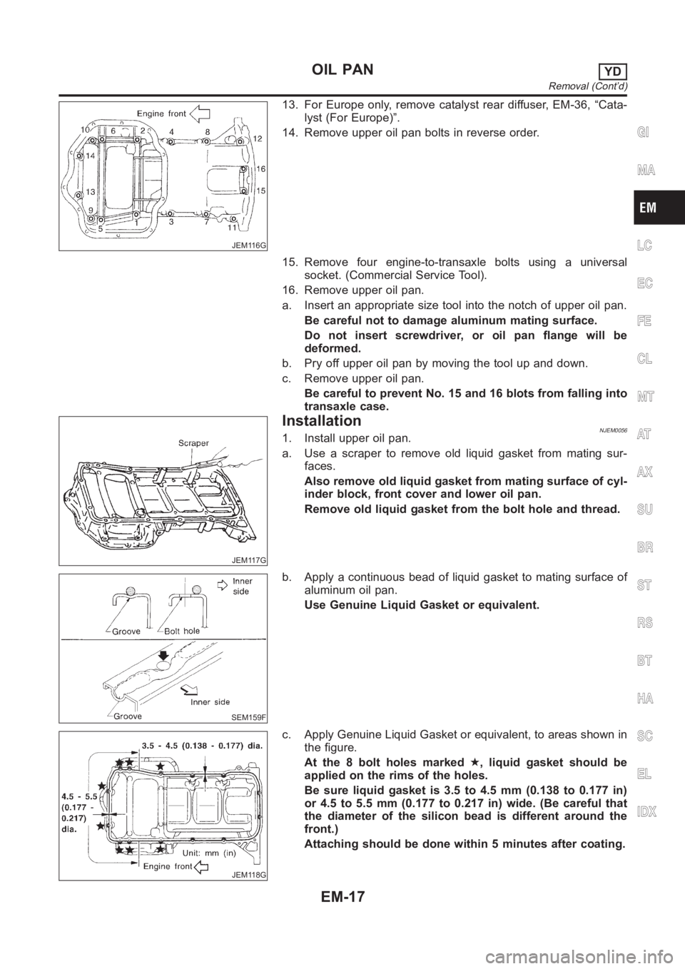
JEM116G
13. For Europe only, remove catalyst rear diffuser, EM-36, “Cata-
lyst (For Europe)”.
14. Remove upper oil pan bolts in reverse order.
15. Remove four engine-to-transaxle bolts using a universal
socket. (Commercial Service Tool).
16. Remove upper oil pan.
a. Insert an appropriate size tool into the notch of upper oil pan.
Be careful not to damage aluminum mating surface.
Do not insert screwdriver, or oil pan flange will be
deformed.
b. Pry off upper oil pan by moving the tool up and down.
c. Remove upper oil pan.
Be careful to prevent No. 15 and 16 blots from falling into
transaxle case.
JEM117G
InstallationNJEM00561. Install upper oil pan.
a. Use a scraper to remove old liquid gasket from mating sur-
faces.
Also remove old liquid gasket from mating surface of cyl-
inder block, front cover and lower oil pan.
Remove old liquid gasket from the bolt hole and thread.
SEM159F
b. Apply a continuous bead of liquid gasket to mating surface of
aluminum oil pan.
Use Genuine Liquid Gasket or equivalent.
JEM118G
c. Apply Genuine Liquid Gasket or equivalent, to areas shown in
the figure.
At the 8 bolt holes marked★, liquid gasket should be
applied on the rims of the holes.
Be sure liquid gasket is 3.5 to 4.5 mm (0.138 to 0.177 in)
or 4.5 to 5.5 mm (0.177 to 0.217 in) wide. (Be careful that
the diameter of the silicon bead is different around the
front.)
Attaching should be done within 5 minutes after coating.
GI
MA
LC
EC
FE
CL
MT
AT
AX
SU
BR
ST
RS
BT
HA
SC
EL
IDX
OIL PANYD
Removal (Cont’d)
EM-17