Page 2704 of 3189

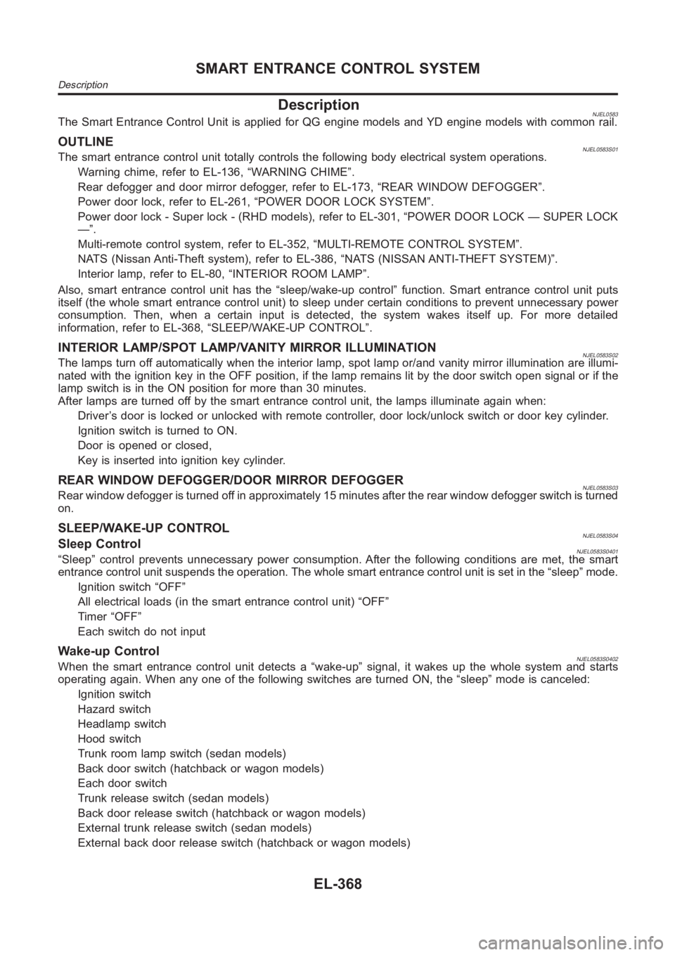
DescriptionNJEL0583The Smart Entrance Control Unit is applied for QG engine models and YD engine models with common rail.
OUTLINENJEL0583S01The smart entrance control unit totally controls the following body electrical system operations.
Warning chime, refer to EL-136, “WARNING CHIME”.
Rear defogger and door mirror defogger, refer to EL-173, “REAR WINDOW DEFOGGER”.
Power door lock, refer to EL-261, “POWER DOOR LOCK SYSTEM”.
Power door lock - Super lock - (RHD models), refer to EL-301, “POWER DOOR LOCK — SUPER LOCK
—”.
Multi-remote control system, refer to EL-352, “MULTI-REMOTE CONTROL SYSTEM”.
NATS (Nissan Anti-Theft system), refer to EL-386, “NATS (NISSAN ANTI-THEFT SYSTEM)”.
Interior lamp, refer to EL-80, “INTERIOR ROOM LAMP”.
Also, smart entrance control unit has the “sleep/wake-up control” function. Smart entrance control unit puts
itself (the whole smart entrance control unit) to sleep under certain conditions to prevent unnecessary power
consumption. Then, when a certain input is detected, the system wakes itself up. For more detailed
information, refer to EL-368, “SLEEP/WAKE-UP CONTROL”.
INTERIOR LAMP/SPOT LAMP/VANITY MIRROR ILLUMINATIONNJEL0583S02The lamps turn off automatically when the interior lamp, spot lamp or/and vanity mirror illumination are illumi-
nated with the ignition key in the OFF position, if the lamp remains lit by the door switch open signal or if the
lamp switch is in the ON position for more than 30 minutes.
After lamps are turned off by the smart entrance control unit, the lamps illuminate again when:
Driver’s door is locked or unlocked with remote controller, door lock/unlock switch or door key cylinder.
Ignition switch is turned to ON.
Door is opened or closed,
Key is inserted into ignition key cylinder.
REAR WINDOW DEFOGGER/DOOR MIRROR DEFOGGERNJEL0583S03Rear window defogger is turned off in approximately 15 minutes after the rear window defogger switch is turned
on.
SLEEP/WAKE-UP CONTROLNJEL0583S04Sleep ControlNJEL0583S0401“Sleep” control prevents unnecessary power consumption. After the following conditions are met, the smart
entrance control unit suspends the operation. The whole smart entrance control unit is set in the “sleep” mode.
Ignition switch “OFF”
All electrical loads (in the smart entrance control unit) “OFF”
Timer “OFF”
Each switch do not input
Wake-up ControlNJEL0583S0402When the smart entrance control unit detects a “wake-up” signal, it wakes up the whole system and starts
operating again. When any one of the following switches are turned ON, the “sleep” mode is canceled:
Ignition switch
Hazard switch
Headlamp switch
Hood switch
Trunk room lamp switch (sedan models)
Back door switch (hatchback or wagon models)
Each door switch
Trunk release switch (sedan models)
Back door release switch (hatchback or wagon models)
External trunk release switch (sedan models)
External back door release switch (hatchback or wagon models)
SMART ENTRANCE CONTROL SYSTEM
Description
EL-368
Page 2712 of 3189

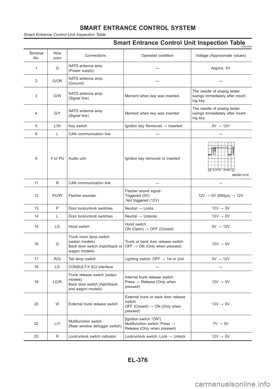
Smart Entrance Control Unit Inspection TableNJEL0586
Terminal
No.Wire
colorConnections Operated condition Voltage (Approximate values)
1GNATS antenna amp.
(Power supply)— Approx. 5V
2 G/ORNATS antenna amp.
(Ground)——
3 G/WNATS antenna amp.
(Signal line)Moment when key was inserted.The needle of analog tester
swings immediately after insert-
ing key.
4 G/YNATS antenna amp.
(Signal line)Moment when key was insertedThe needle of analog tester
swings immediately after insert-
ing key.
5 L/W Key switch Ignition key Removed,Inserted 0V,12V
8 L CAN communication line — —
9 Y or PU Audio unit Ignition key removed or inserted
MKIB0191E
11 R CAN communication line — —
12 PU/W Flasher sounderFlasher sound signal :
Triggered (0V)
.Not triggered (12V)12V,0V (850μs),12V
13 P Door lock/unlock switches Neutral,Locks 12V,0V
14 L Door lock/unlock switches Neutral,Unlocks 12V,0V
15 LG Hood switchHood switch:
ON (Open),OFF (Closed)0V,12V
16 GTrunk room lamp switch
(sedan models)
Back door switch (hatchback or
wagon models)Trunk or back door release switch:
OFF,ON (Only when pressed)12V,0V
17 R/G Tail lamp switch Lighting switch: OFF,1st or 2nd 0V,12V
18 LG CONSULT-II SCI interface — —
19 LG/RTrunk release switch (sedan
models)
Back door switch (hatchback
and wagon models)Internal trunk release switch:
Press,Release (Only when
pressed)12V,0V
20 W External trunk release switchExternal trunk or back door release
switch:
OFF (Closed),ON (Only when
pressed)12V,0V
22 L/YMultifunction switch
(Rear window defogger switch)[Ignition switch “ON”]
Multifunction switch: Press,
Release (Only when pressed)7V,0V
23 R Lock/unlock switch indicator Lock/unlock switch: Lock,Unlock 12V,0V
SMART ENTRANCE CONTROL SYSTEM
Smart Entrance Control Unit Inspection Table
EL-376
Page 2722 of 3189

Component Parts and Harness Connetor
Location
NJEL0406For details, refer to “ELECTRICAL UNIT LOCATION” (EL-543) and
“HARNESS LAYOUT” (EL-550).
System DescriptionNJEL0407NATS (Nissan Anti-Theft System) has the following immobilizer functions:
Since only NATS ignition keys, whose ID nos. have been registered into the ECM and IMMU of NATS,
allow the engine to run, operation of a stolen vehicle without a NATS registered key is prevented by NATS.
That is to say, NATS will immobilize the engine if someone tries to start it without the registered key of
NATS.
This version of NATS has dongle unit to improve its anti-theft performance(RHD models for Europe).
Dongle unit has its own ID which is registered into NATS IMMU. So if dongle unit is replaced, initialization
must be carried out.
When malfunction of dongle unit is detected:
The security indicator lamp illuminates for about 15 minutes after ignition switch is turned to ON.
− When dongle unit has a malfunction and the indicator lamp is illuminated,engine can not be started.
However engine can be started only one time when security indicator lamp turns off in about 15 minutes
after ignition switch is turned to ON.
All of the originally supplied ignition key IDs have been NATS registered.
If requested by the vehicle owner, a maximum of five key IDs can be registered into the NATS compo-
nents.
The security indicator blinks when the ignition switch is in “OFF” or “ACC”position. Therefore, NATS warns
outsiders that the vehicle is equipped with the anti-theft system.
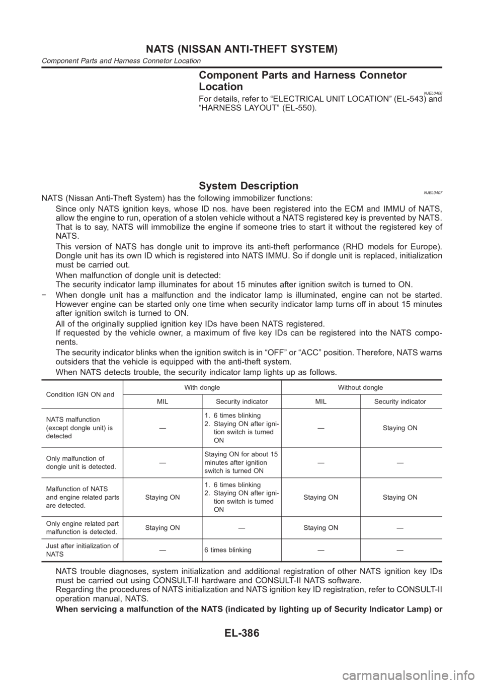
When NATS detects trouble, the security indicator lamp lights up as follows.
Condition IGN ON andWith dongle Without dongle
MIL Security indicator MIL Security indicator
NATS malfunction
(except dongle unit) is
detected—1. 6 times blinking
2. Staying ON after igni-
tion switch is turned
ON— Staying ON
Only malfunction of
dongle unit is detected.—Staying ON for about 15
minutes after ignition
switch is turned ON——
Malfunction of NATS
and engine related parts
are detected.Staying ON1. 6 times blinking
2. Staying ON after igni-
tion switch is turned
ONStaying ON Staying ON
Only engine related part
malfunction is detected.Staying ON — Staying ON —
Just after initialization of
NATS— 6 times blinking — —
NATS trouble diagnoses, system initialization and additional registration of other NATS ignition key IDs
must be carried out using CONSULT-II hardware and CONSULT-II NATS software.
Regarding the procedures of NATS initialization and NATS ignition key ID registration, refer to CONSULT-II
operation manual, NATS.
When servicing a malfunction of the NATS (indicated by lighting up of Security Indicator Lamp) or
NATS (NISSAN ANTI-THEFT SYSTEM)
Component Parts and Harness Connetor Location
EL-386
Page 2723 of 3189
registering another NATS ignition key ID no., it may be necessary to re-register original key iden-
tification. Therefore, be sure to receive ALL KEYS from vehicle owner.
System CompositionNJEL0408The immobilizer function of the NATS consists of the following:
NATS ignition key
NATS immobilizer control unit (IMMU) located in the ignition key cylinder
Engine control module (ECM)
Dongle unit (RHD models)
Security indicator
Navigation control unit (Models with Navigation system)
NEL776
GI
MA
EM
LC
EC
FE
CL
MT
AT
AX
SU
BR
ST
RS
BT
HA
SC
IDX
NATS (NISSAN ANTI-THEFT SYSTEM)
System Description (Cont’d)
EL-387
Page 2724 of 3189
Wiring Diagram — NATS —NJEL0487QG ENGINE MODELS AND YD ENGINE MODELS WITH COMMON RAILNJEL0487S06
YEL771D
NATS (NISSAN ANTI-THEFT SYSTEM)
Wiring Diagram — NATS —
EL-388
Page 2725 of 3189
YD ENGINE MODELS WITHOUT COMMON RAILNJEL0487S07
YEL772D
GI
MA
EM
LC
EC
FE
CL
MT
AT
AX
SU
BR
ST
RS
BT
HA
SC
IDX
NATS (NISSAN ANTI-THEFT SYSTEM)
Wiring Diagram — NATS — (Cont’d)
EL-389
Page 2726 of 3189
SEF094Y
CONSULT-IINJEL0410CONSULT-II INSPECTION PROCEDURENJEL0410S011. Turn ignition switch OFF.
PBR455D
2. Insert NATS program card into CONSULT-II.
: Program card
NATS-AEN02B
3. Connect CONSULT-II to data link connector.
4. Turn ignition switch ON.
5. Touch “START”.
SEL027X
6. Select “NATS V.5.0”.
SEL150X
7. Perform each diagnostic test mode according to each service
procedure.
For further information, see the CONSULT-II Operation
Manual, NATS.
NATS (NISSAN ANTI-THEFT SYSTEM)
CONSULT-II
EL-390
Page 2727 of 3189

CONSULT-II DIAGNOSTIC TEST MODE FUNCTION=NJEL0410S02
CONSULT-II DIAGNOSTIC TEST
MODEDescription
C/U INITIALIZATION When replacing any of the following components, C/U initialization and re-registration of all
NATS ignition keys are necessary.
[NATS ignition key/IMMU/ECM/Dongle unit]
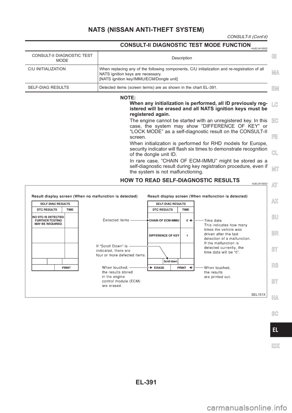
SELF-DIAG RESULTS Detected items (screen terms) are as shown in the chart EL-391.
NOTE:
When any initialization is performed, all ID previously reg-
istered will be erased and all NATS ignition keys must be
registered again.
The engine cannot be started with an unregistered key. In this
case, the system may show “DIFFERENCE OF KEY” or
“LOCK MODE” as a self-diagnostic result on the CONSULT-II
screen.
When initialization is performed for RHD models for Europe,
security indicator will flash six times to demonstrate recognition
of the dongle unit ID.
In rare case, “CHAIN OF ECM-IMMU” might be stored as a
self-diagnostic result during key registration procedure, even if
the system is not malfunctioning.
HOW TO READ SELF-DIAGNOSTIC RESULTSNJEL0410S03
SEL151X
GI
MA
EM
LC
EC
FE
CL
MT
AT
AX
SU
BR
ST
RS
BT
HA
SC
IDX
NATS (NISSAN ANTI-THEFT SYSTEM)
CONSULT-II (Cont’d)
EL-391