Page 2459 of 3189
INSPECTION/VEHICLE SPEED SIGNAL=NJEL0448S04Models without ABSNJEL0448S0401
1 CHECK VEHICLE SPEED SENSOR OUTPUT
1. Remove vehicle speed sensor from transmission.
2. Check voltage between combination meter terminal 13 and ground while quickly turning speed sensor pinion.
YEL795C
OK or NG
OK Vehicle speed sensor signal is OK.
NG GO TO 2.
2 CHECK VEHICLE SPEED SENSOR
Check resistance between vehicle speed sensor terminals 1 and 2.
SEL645WA
OK or NG
OKCheck the following.
Harness between combination meter and vehicle speed sensor
Vehicle speed sensor ground circuit
NG Replace vehicle speed sensor.
GI
MA
EM
LC
EC
FE
CL
MT
AT
AX
SU
BR
ST
RS
BT
HA
SC
IDX
METERS AND GAUGES
Trouble Diagnoses (Cont’d)
EL-123
Page 2460 of 3189

Models with ABS=NJEL0448S0402
1 ABS ACTUATOR AND ELECTRIC UNIT SYSTEM INSPECTION
Perform ABS actuator and electric unit self-diagnosis.
Refer to BR-55, “CONSULT-II Functions”.
OK or NG
OK GO TO 2.
NG Check ABS control system. Refer to BR-62, “TROUBLE DIAGNOSIS — BASIC INSPEC-
TION”.
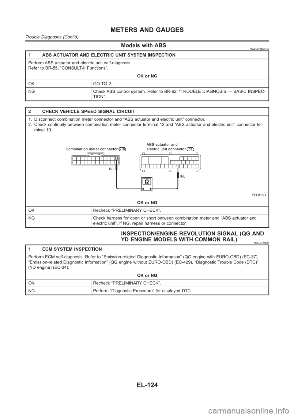
2 CHECK VEHICLE SPEED SIGNAL CIRCUIT
1. Disconnect combination meter connector and “ABS actuator and electricunit” connector.
2. Check continuity between combination meter connector terminal 12 and “ABS actuator and electric unit” connector ter-
minal 10.
YEL815D
OK or NG
OK Recheck “PRELIMINARY CHECK”.
NG Check harness for open or short between combination meter and “ABS actuator and
electric unit”. If NG, repair harness or connector.
INSPECTION/ENGINE REVOLUTION SIGNAL (QG AND
YD ENGINE MODELS WITH COMMON RAIL)
NJEL0448S11
1 ECM SYSTEM INSPECTION
Perform ECM self-diagnosis. Refer to “Emission-related Diagnostic Information” (QG engine with EURO-OBD) (EC-37),
“Emission-related Diagnostic Information” (QG engine without EURO-OBD) (EC-429), “Diagnostic Trouble Code (DTC)”
(YD engine) (EC-34).
OK or NG
OK Recheck “PRELIMINARY CHECK”.
NG Perform “Diagnostic Procedure” for displayed DTC.
METERS AND GAUGES
Trouble Diagnoses (Cont’d)
EL-124
Page 2461 of 3189
INSPECTION/ENGINE REVOLUTION SIGNAL (YD
ENGINE MODELS WITHOUT COMMON RAIL)
=NJEL0448S05
1 CHECK ECM OUTPUT
1. Start engine.
2. Check voltage between combination meter terminals 53 and ground at idleand 2,000 rpm.
YEL816D
OK or NG
OK Engine revolution signal is OK.
NG Harness for open or short between ECM and combination meter
GI
MA
EM
LC
EC
FE
CL
MT
AT
AX
SU
BR
ST
RS
BT
HA
SC
IDX
METERS AND GAUGES
Trouble Diagnoses (Cont’d)
EL-125
Page 2462 of 3189
INSPECTION/FUEL LEVEL SENSOR UNIT=NJEL0448S06
1 CHECK GROUND CIRCUIT FOR FUEL LEVEL SENSOR UNIT
Check harness continuity between fuel level sensor unit connector terminal 1 and ground.
SEL400X
OK or NG
OK GO TO 2.
NG Repair harness or connector.
2 CHECK FUEL LEVEL SENSOR UNIT
Refer to “FUEL LEVEL SENSOR UNIT CHECK” (EL-128).
OK or NG
OK GO TO 3.
NG Replace fuel level sensor unit.
3 CHECK HARNESS FOR OPEN OR SHORT
1. Disconnect combination meter connector and fuel level sensor unit connector.
2. Check continuity between combination meter terminal 34 and fuel level sensor unit connector terminal 4.
Continuity should exist.
3. Check continuity between combination meter terminal 34 and ground.
Continuity should not exist.
YEL817D
OK or NG
OK Fuel level sensor unit is OK.
NG Repair harness or connector.
METERS AND GAUGES
Trouble Diagnoses (Cont’d)
EL-126
Page 2463 of 3189

INSPECTION/THERMAL TRANSMITTER (YD ENGINE
MODELS WITHOUT COMMON RAIL)
=NJEL0448S07
1 CHECK THERMAL TRANSMITTER
Refer to “THERMAL TRANSMITTER CHECK” (EL-128).
OK or NG
OK GO TO 2.
NG Replace.
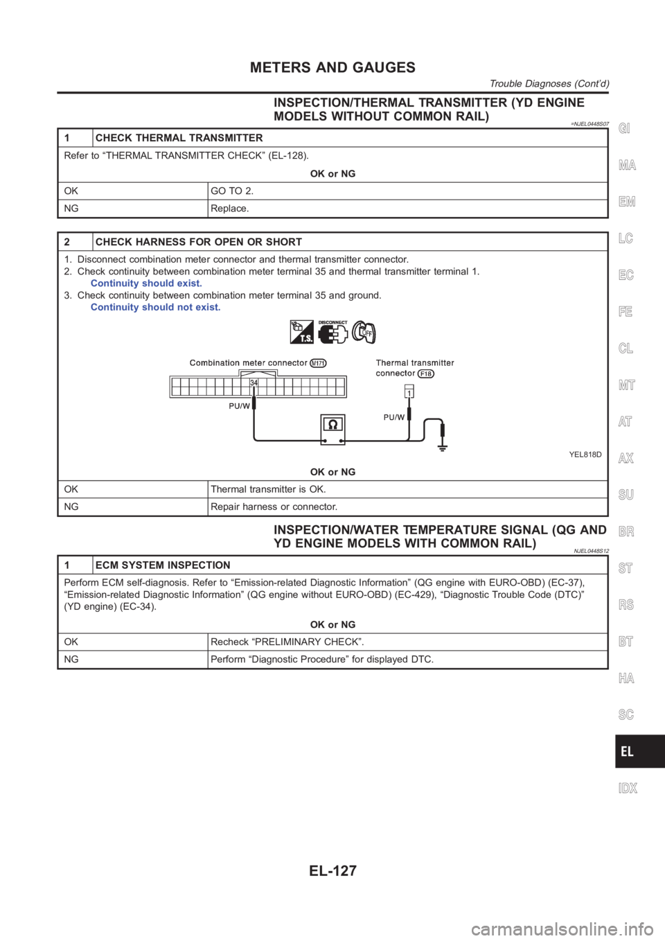
2 CHECK HARNESS FOR OPEN OR SHORT
1. Disconnect combination meter connector and thermal transmitter connector.
2. Check continuity between combination meter terminal 35 and thermal transmitter terminal 1.
Continuity should exist.
3. Check continuity between combination meter terminal 35 and ground.
Continuity should not exist.
YEL818D
OK or NG
OK Thermal transmitter is OK.
NG Repair harness or connector.
INSPECTION/WATER TEMPERATURE SIGNAL (QG AND
YD ENGINE MODELS WITH COMMON RAIL)
NJEL0448S12
1 ECM SYSTEM INSPECTION
Perform ECM self-diagnosis. Refer to “Emission-related Diagnostic Information” (QG engine with EURO-OBD) (EC-37),
“Emission-related Diagnostic Information” (QG engine without EURO-OBD) (EC-429), “Diagnostic Trouble Code (DTC)”
(YD engine) (EC-34).
OK or NG
OK Recheck “PRELIMINARY CHECK”.
NG Perform “Diagnostic Procedure” for displayed DTC.
GI
MA
EM
LC
EC
FE
CL
MT
AT
AX
SU
BR
ST
RS
BT
HA
SC
IDX
METERS AND GAUGES
Trouble Diagnoses (Cont’d)
EL-127
Page 2471 of 3189

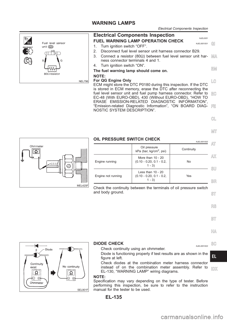
NEL796
Electrical Components InspectionNJEL0051FUEL WARNING LAMP OPERATION CHECKNJEL0051S011. Turn ignition switch “OFF”.
2. Disconnect fuel level sensor unit harness connector B29.
3. Connect a resistor (80Ω) between fuel level sensor unit har-
ness connector terminals 4 and 1.
4. Turn ignition switch “ON”.
The fuel warning lamp should come on.
NOTE:
For QG Engine Only
ECM might store the DTC P0180 during this inspection. If the DTC
is stored in ECM memory, erase the DTC after reconnecting the
fuel level sensor unit and fuel pump harness connector. Refer to
EC-48 (With EURO-OBD), 430 (Without EURO-OBD), “HOW TO
ERASE EMISSION-RELATED DIAGNOSTIC INFORMATION”,
“Emission-related Diagnostic Information”, “ON BOARD DIAG-
NOSTIC SYSTEM DESCRIPTION”.
MEL425F
OIL PRESSURE SWITCH CHECKNJEL0051S02
Oil pressure
kPa (bar, kg/cm2, psi)Continuity
Engine runningMore than 10 - 20
(0.10 - 0.20, 0.1 - 0.2,
1-3)No
Engine not runningLess than 10 - 20
(0.10 - 0.20, 0.1 - 0.2,
1-3)Ye s
Check the continuity between the terminals of oil pressure switch
and body ground.
SEL901F
DIODE CHECKNJEL0051S03Check continuity using an ohmmeter.
Diode is functioning properly if test results are as shown in the
figure at left.
Check diodes at the combination meter harness connector
instead of on the combination meter assembly. Refer to
EL-130, “WARNING LAMP” wiring diagrams.
NOTE:
Specification may vary depending on the type of tester. Before
performing this inspection, be sure to refer to the instruction
manual for the tester to be used.
GI
MA
EM
LC
EC
FE
CL
MT
AT
AX
SU
BR
ST
RS
BT
HA
SC
IDX
WARNING LAMPS
Electrical Components Inspection
EL-135
Page 2530 of 3189
SPEED DEPENDENT VOLUME CONTROLNJEL0497S13DescriptionNJEL0497S1301If activated, the radio output volume will be automatically adjusted to compensate for increased driving noises
at higher driving speeds.
The radio receives a speed signal from the combination meter and selects the output volume.
PERSONAL AUDIO SETTINGSNJEL0497S14DescriptionNJEL0497S1401The radio is designed to store several settings (volume, bass, treble, preset stations and level of speed
dependent volume control) with every NATS ignition key used. Up to a maximum of 4 NATS keys can be reg-
istered. During the communication mentioned under “Anti-Theft System”,the radio will recognize the used
ignition key and select the accompanying settings.
Component Parts LocationNJEL0554EL-543, “ELECTRIC UNIT LOCATION”.
AUDIO
System Description (Cont’d)
EL-194
Page 2551 of 3189

System DescriptionNJEL0555MULTIFUNCTION SWITCH SYSTEMNJEL0555S01Refer to Owner′s Manual for multifunction switch operating instruc-
tions.
Using the multifunction switch at the center of the instrument panel,
it can be operating the following systems:
Auto A/C system
Board computer
Audio system
POWER SUPPLY AND GROUNDNJEL0555S02Power is Supplied at All TimesNJEL0555S0201through 15A fuse (No. 40, located in fuse and fusible link box)
to display unit terminal 23
to audio unit terminals 3 and 4.
When Ignition Switch is in ACC or ON Position, Power
is Supplied
NJEL0555S0202through 10A fuse [No. 1, located in fuse block (J/B)]
to display unit terminal 24,
to multifunction switch terminal 6 and
to audio unit terminal 2.
When Ignition Switch is in ON or START Position,
Power is Supplied
NJEL0555S0203through 10A fuse [No. 1, located in fuse block (J/B)]
to display unit terminal 22.
Ground is SuppliedNJEL0555S0204to multifunction switch terminal 1 and
to display unit terminal 21
through body grounds M28, M67 and F118 (Gasoline engine
models).
AV COMMUNICATION LINENJEL0555S03Display unit is communicated by the following unit with communi-
cation line.
Multifunction switch
Audio unit
Auto A/C unit
Combination meter
Display unit received operation signal from multifunction switch,
and it send operation signal to audio unit, auto A/C unit or combi-
nation meter.
BOARD COMPUTERNJEL0555S04Refer to Owner′s Manual for board computer operating instruc-
tions.
Board computer is monitoring to the following five type information.
GI
MA
EM
LC
EC
FE
CL
MT
AT
AX
SU
BR
ST
RS
BT
HA
SC
IDX
VFD DISPLAY
System Description
EL-215