Page 2558 of 3189
TERMINALS
SIGNALCONDITION
DATA (+)
(–)
TERMINALWIRE
COLORIGNITION
SWITCHOPERATION
12 B/W GroundCommunication
signal (+)ON —
SKIA0175E
13 P GroundCommunication
signal (−)ON —
SKIA0176E
14 L GroundCommunication
signal (−)ON —
SKIA0176E
15 — Ground Shield ground ON — —
16 — Ground Shield ground ON — —
Trouble DiagnosisNJEL0637SELF-DIAGNOSIS FUNCTIONNJEL0637S01DescriptionNJEL0637S0101Self-diagnosis items are as follows.
Screen of all segments check
Software version and hardware version of display unit are dis-
played on the upper zone of the screen. (This information is not
used for service. Skip this step.)
Dimming steps and levels check
Can be checked communication line between A/C auto amp.,
audio unit, multifunction switch, combination meter and display
unit, and displays the results on the upper zone of the screen.
VFD DISPLAY
Terminals and Reference Value for Multifunction Switch (Cont’d)
EL-222
Page 2559 of 3189

YEL828D
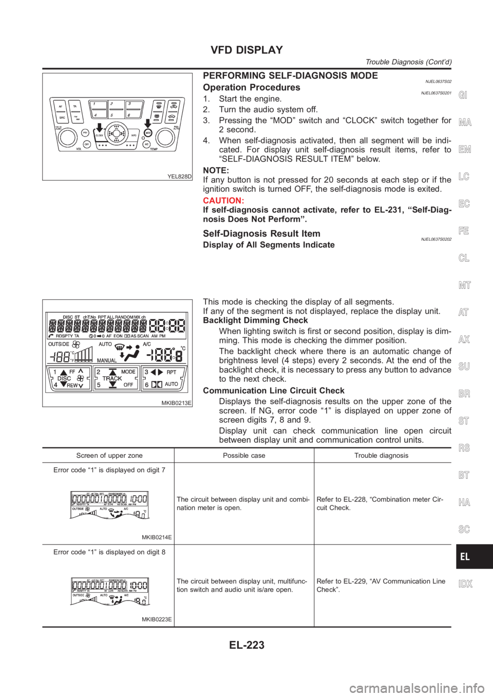
PERFORMING SELF-DIAGNOSIS MODENJEL0637S02Operation ProceduresNJEL0637S02011. Start the engine.
2. Turn the audio system off.
3. Pressing the “MOD” switch and “CLOCK” switch together for
2 second.
4. When self-diagnosis activated, then all segment will be indi-
cated. For display unit self-diagnosis result items, refer to
“SELF-DIAGNOSIS RESULT ITEM” below.
NOTE:
If any button is not pressed for 20 seconds at each step or if the
ignition switch is turned OFF, the self-diagnosis mode is exited.
CAUTION:
If self-diagnosis cannot activate, refer to EL-231, “Self-Diag-
nosis Does Not Perform”.
Self-Diagnosis Result ItemNJEL0637S0202Display of All Segments Indicate
MKIB0213E
This mode is checking the display of all segments.
If any of the segment is not displayed, replace the display unit.
Backlight Dimming Check
When lighting switch is first or second position, display is dim-
ming. This mode is checking the dimmer position.
The backlight check where there is an automatic change of
brightness level (4 steps) every 2 seconds. At the end of the
backlight check, it is necessary to press any button to advance
to the next check.
Communication Line Circuit Check
Displays the self-diagnosis results on the upper zone of the
screen. If NG, error code “1” is displayed on upper zone of
screen digits 7, 8 and 9.
Display unit can check communication line open circuit
between display unit and communication control units.
Screen of upper zone Possible case Trouble diagnosis
Error code “1” is displayed on digit 7
MKIB0214E
The circuit between display unit and combi-
nation meter is open.Refer to EL-228, “Combination meter Cir-
cuit Check.
Error code “1” is displayed on digit 8
MKIB0223E
The circuit between display unit, multifunc-
tion switch and audio unit is/are open.Refer to EL-229, “AV Communication Line
Check”.
GI
MA
EM
LC
EC
FE
CL
MT
AT
AX
SU
BR
ST
RS
BT
HA
SC
IDX
VFD DISPLAY
Trouble Diagnosis (Cont’d)
EL-223
Page 2564 of 3189
COMBINATION METER CIRCUIT CHECKNJEL0637S05
1 COMMUNICATION LINE (MA-AV, AV-ME) CIRCUIT CHECK
1. Disconnect the display unit connector and combination meter connector.
YEL829D
2. Check continuity between display unit and ground.
MTBL1465
3. Check continuity between display unit and combination meter.
MTBL1466
OK or NG
OK Check combination meter.
NG Replace harness or connector.
VFD DISPLAY
Trouble Diagnosis (Cont’d)
EL-228
Page 2571 of 3189
NO AVERAGE SPEED DISPLAYED/LHD MODELS=NJEL0637S10
1 DISPLAY SELF-DIAGNOSIS
1. Perform self-diagnosis display unit. Refer to EL-223, “Performing Self-Diagnosis Mode”.
2. All VFD display segments are ON.
OK or NG
OK GO TO 2.
NG Replace display unit.
2 HARNESS CHECK
1. Disconnect display unit connector and combination meter.
2. Check the following.
YEL831D
– Continuity between display unit connector M99 terminal 19 (L/B) and combination meter connector M171 terminal 56
(L/B).
Continuity should exist.
– Continuity between display unit connector M99 terminal 19 (L/B) and ground.
Continuity should not exist.
OK or NG
OK GO TO 3.
NG Replace harness or connector.
GI
MA
EM
LC
EC
FE
CL
MT
AT
AX
SU
BR
ST
RS
BT
HA
SC
IDX
VFD DISPLAY
Trouble Diagnosis (Cont’d)
EL-235
Page 2572 of 3189

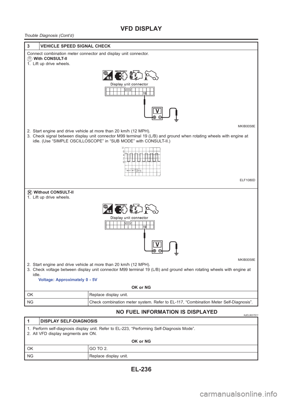
3 VEHICLE SPEED SIGNAL CHECK
Connect combination meter connector and display unit connector.
With CONSULT-ll
1. Lift up drive wheels.
MKIB0058E
2. Start engine and drive vehicle at more than 20 km/h (12 MPH).
3. Check signal between display unit connector M99 terminal 19 (L/B) and ground when rotating wheels with engine at
idle. (Use “SIMPLE OSCILLOSCOPE” in “SUB MODE” with CONSULT-II.)
ELF1080D
Without CONSULT-ll
1. Lift up drive wheels.
MKIB0058E
2. Start engine and drive vehicle at more than 20 km/h (12 MPH).
3. Check voltage between display unit connector M99 terminal 19 (L/B) and ground when rotating wheels with engine at
idle.
Voltage: Approximately 0 - 5V
OK or NG
OK Replace display unit.
NG Check combination meter system. Refer to EL-117, “Combination Meter Self-Diagnosis”.
NO FUEL INFORMATION IS DISPLAYEDNJEL0637S11
1 DISPLAY SELF-DIAGNOSIS
1. Perform self-diagnosis display unit. Refer to EL-223, “Performing Self-Diagnosis Mode”.
2. All VFD display segments are ON.
OK or NG
OK GO TO 2.
NG Replace display unit.
VFD DISPLAY
Trouble Diagnosis (Cont’d)
EL-236
Page 2573 of 3189
2 COMMUNICATION LINE (MA-AV, AV-ME) CIRCUIT CHECK
1. Disconnect the display unit connector and combination meter connector.
YEL829D
2. Check continuity between display unit and ground.
MTBL1478
3. Check continuity between display unit and combination meter.
MTBL1479
OK or NG
OK Check combination meter.
NG Replace harness or connector.
GI
MA
EM
LC
EC
FE
CL
MT
AT
AX
SU
BR
ST
RS
BT
HA
SC
IDX
VFD DISPLAY
Trouble Diagnosis (Cont’d)
EL-237
Page 2576 of 3189

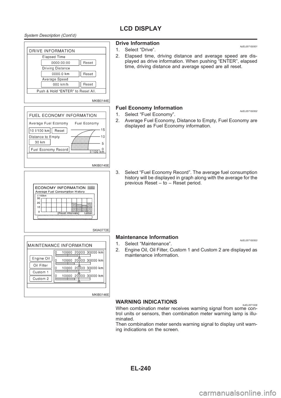
MKIB0144E
Drive InformationNJEL0571S05011. Select “Drive”.
2. Elapsed time, driving distance and average speed are dis-
played as drive information. When pushing “ENTER”, elapsed
time, driving distance and average speed are all reset.
MKIB0145E
Fuel Economy InformationNJEL0571S05021. Select “Fuel Economy”.
2. Average Fuel Economy, Distance to Empty, Fuel Economy are
displayed as Fuel Economy information.
SKIA0772E
3. Select “Fuel Economy Record”. The average fuel consumption
history will be displayed in graph along with the average for the
previous Reset – to – Reset period.
MKIB0146E
Maintenance InformationNJEL0571S05031. Select “Maintenance”.
2. Engine Oil, Oil Filter, Custom 1 and Custom 2 are displayed as
maintenance information.
WARNING INDICATIONSNJEL0571S06When combination meter receives warning signal from some con-
trol units or sensors, then combination meter warning lamp is illu-
minated.
Then combination meter sends warning signal to display unit warn-
ing indications on the screen.
LCD DISPLAY
System Description (Cont’d)
EL-240
Page 2705 of 3189

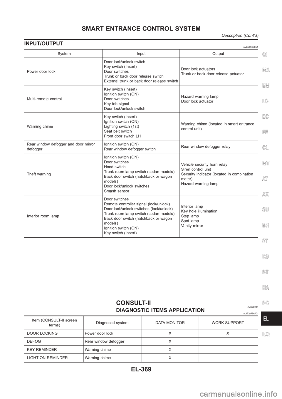
INPUT/OUTPUTNJEL0583S05
System Input Output
Power door lockDoor lock/unlock switch
Key switch (Insert)
Door switches
Trunk or back door release switch
External trunk or back door release switchDoor lock actuators
Trunk or back door release actuator
Multi-remote controlKey switch (Insert)
Ignition switch (ON)
Door switches
Key fob signal
Door lock/unlock switchHazard warning lamp
Door lock actuator
Warning chimeKey switch (Insert)
Ignition switch (ON)
Lighting switch (1st)
Seat belt switch
Front door switch LHWarning chime (located in smart entrance
control unit)
Rear window defogger and door mirror
defoggerIgnition switch (ON)
Rear window defogger switchRear window defogger relay
Theft warningIgnition switch (ON)
Door switches
Hood switch
Trunk room lamp switch (sedan models)
Back door switch (hatchback or wagon
models)
Door lock/unlock switches
Smash sensorVehicle security horn relay
Siren control unit
Security indicator (located in combination
meter)
Hazard warning lamp
Interior room lampDoor switches
Remote controller signal (lock/unlock)
Door lock/unlock switches (lock/unlock)
Trunk room lamp switch (sedan models)
Back door switch (hatchback or wagon
models)
Ignition switch (ON)
Key switch (Insert)Interior lamp
Key hole illumination
Step lamp
Spot lamp
Vanity mirror
CONSULT-IINJEL0584DIAGNOSTIC ITEMS APPLICATIONNJEL0584S01
Item (CONSULT-II screen
terms)Diagnosed system DATA MONITOR WORK SUPPORT
DOOR LOCKING Power door lock X X
DEFOG Rear window defogger X
KEY REMINDER Warning chime X
LIGHT ON REMINDER Warning chime X
GI
MA
EM
LC
EC
FE
CL
MT
AT
AX
SU
BR
ST
RS
BT
HA
SC
IDX
SMART ENTRANCE CONTROL SYSTEM
Description (Cont’d)
EL-369