Page 2832 of 3189
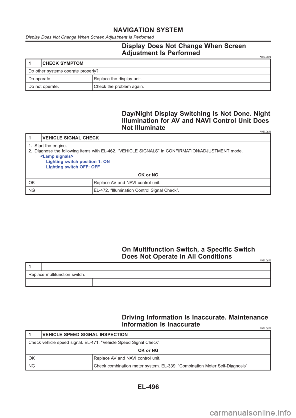
Display Does Not Change When Screen
Adjustment Is Performed
NJEL0624
1 CHECK SYMPTOM
Do other systems operate properly?
Do operate. Replace the display unit.
Do not operate. Check the problem again.
Day/Night Display Switching Is Not Done. Night
Illumination for AV and NAVI Control Unit Does
Not Illuminate
NJEL0625
1 VEHICLE SIGNAL CHECK
1. Start the engine.
2. Diagnose the following items with EL-462, “VEHICLE SIGNALS” in CONFIRMATION/ADJUSTMENT mode.
Lighting switch position 1: ON
Lighting switch OFF: OFF
OK or NG
OK Replace AV and NAVI control unit.
NG EL-472, “Illumination Control Signal Check”.
On Multifunction Switch, a Specific Switch
Does Not Operate in All Conditions
NJEL0626
1
Replace multifunction switch.
Driving Information Is Inaccurate. Maintenance
Information Is Inaccurate
NJEL0627
1 VEHICLE SPEED SIGNAL INSPECTION
Check vehicle speed signal. EL-471, “Vehicle Speed Signal Check”.
OK or NG
OK Replace AV and NAVI control unit.
NG Check combination meter system. EL-339, “Combination Meter Self-Diagnosis”
NAVIGATION SYSTEM
Display Does Not Change When Screen Adjustment Is Performed
EL-496
Page 2845 of 3189
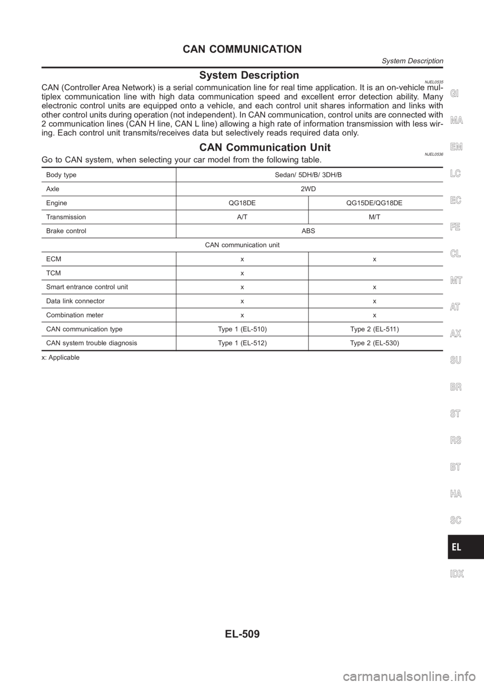
System DescriptionNJEL0535CAN (Controller Area Network) is a serial communication line for real timeapplication. It is an on-vehicle mul-
tiplex communication line with high data communication speed and excellent error detection ability. Many
electronic control units are equipped onto a vehicle, and each control unit shares information and links with
other control units during operation (not independent). In CAN communication, control units are connected with
2 communication lines (CAN H line, CAN L line) allowing a high rate of information transmission with less wir-
ing. Each control unit transmits/receives data but selectively reads requireddataonly.
CAN Communication UnitNJEL0536Go to CAN system, when selecting your car model from the following table.
Body type Sedan/ 5DH/B/ 3DH/B
Axle2WD
Engine QG18DE QG15DE/QG18DE
Transmission A/T M/T
Brake controlABS
CAN communication unit
ECM x x
TCM x
Smart entrance control unit x x
Data link connector x x
Combination meter x x
CAN communication type Type 1 (EL-510) Type 2 (EL-511)
CAN system trouble diagnosis Type 1 (EL-512) Type 2 (EL-530)
x: Applicable
GI
MA
EM
LC
EC
FE
CL
MT
AT
AX
SU
BR
ST
RS
BT
HA
SC
IDX
CAN COMMUNICATION
System Description
EL-509
Page 2846 of 3189
TYPE 1=NJEL0536S01System DiagramNJEL0536S0101
SEL825Y
Input/Output Signal ChartNJEL0536S0102T: Transmit R: Receive
Signals ECM TCMSmart entrance
control unitCombination meter
Engine speed signal T R
Brake switch signal R T
Rear window defogger signal R T
Heater fan switch signal R T
Air conditioner switch signal R T
MI signal T R
Current gear position signal T R
Engine coolant temperature signal T R
Fuel consumption signal T R
Vehicle speed signal R T
Seat belt reminder signalRT
Headlamp switch signalTR
Flashing indicator signalTR
Engine cooling fan speed signal T R
Child lock indicator signalTR
Door switches state signal T R
A/C compressor signal T R
Accelerator pedal position signal T R
Output shaft revolution signal R T
OD OFF switch signal R T
OD OFF indicator signal T R
A/T self-diagnosis signal R T
CAN COMMUNICATION
CAN Communication Unit (Cont’d)
EL-510
Page 2847 of 3189
TYPE 2=NJEL0536S02System DiagramNJEL0536S0201
SEL826Y
Input/Output Signal ChartNJEL0536S0202T: Transmit R: Receive
Signals ECMSmart entrance control
unitCombination meter
Engine speed signal T R
Rear window defogger signal R T
Heater fan switch signal R T
Air conditioner switch signal R T
MI signal T R
Engine coolant temperature signal T R
Fuel consumption signal T R
Vehicle speed signal R T
Seat belt reminder signal R T
Headlamp switch signal T R
Flashing indicator signal T R
Engine cooling fan speed signal T R
Child lock indicator signal T R
Door switches state signal T R
A/C compressor signal T R
GI
MA
EM
LC
EC
FE
CL
MT
AT
AX
SU
BR
ST
RS
BT
HA
SC
IDX
CAN COMMUNICATION
CAN Communication Unit (Cont’d)
EL-511
Page 2854 of 3189
SEL807Y
INSPECTIONNJEL0540S04Proceed trouble diagnosis according to the check sheet results (example).
Case 1: Replace ECM.
Case 2: Replace TCM.
Case 3: Replace smart entrance control unit.
Case 4: Check harness between TCM and smart entrance control unit. Refer to“CIRCUIT CHECK BETWEEN
TCM AND SMART ENTRANCE CONTROL UNIT” (EL-519).
Case 5: Check ECM circuit. Refer to “ECM CIRCUIT CHECK” (EL-522).
Case 6: Check TCM circuit. Refer to “TCM CIRCUIT CHECK” (EL-523).
Case 7: Check smart entrance control unit circuit. Refer to “SMART ENTRANCE CONTROL UNIT CIRCUIT
CHECK” (EL-524).
Case 8: Check combination meter circuit. Refer to “COMBINATION METER CIRCUIT CHECK” (EL-525).
Case 9: Check CAN communication circuit. Refer to “CAN COMMUNICATION CIRCUIT CHECK” (EL-525).
CAN SYSTEM (TYPE 1)
Trouble Diagnoses (Cont’d)
EL-518
Page 2861 of 3189
COMBINATION METER CIRCUIT CHECK=NJEL0540S09
1 CHECK CONNECTOR
1. Turn ignition switch OFF.
2. Disconnect the negative battery cable.
3. Check following terminals and connector of combination meter for damage, bend and loose connection (meter-side and
harness-side).
OK or NG
OK GO TO 2.
NG Repair terminal or connector.
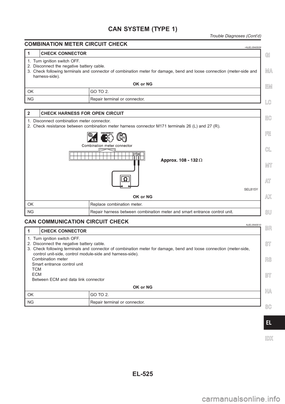
2 CHECK HARNESS FOR OPEN CIRCUIT
1. Disconnect combination meter connector.
2. Check resistance between combination meter harness connector M171 terminals 26 (L) and 27 (R).
SEL815Y
OK or NG
OK Replace combination meter.
NG Repair harness between combination meter and smart entrance control unit.
CAN COMMUNICATION CIRCUIT CHECKNJEL0540S10
1 CHECK CONNECTOR
1. Turn ignition switch OFF.
2. Disconnect the negative battery cable.
3. Check following terminals and connector of combination meter for damage, bend and loose connection (meter-side,
control unit-side, control module-side and harness-side).
Combination meter
Smart entrance control unit
TCM
ECM
Between ECM and data link connector
OK or NG
OK GO TO 2.
NG Repair terminal or connector.
GI
MA
EM
LC
EC
FE
CL
MT
AT
AX
SU
BR
ST
RS
BT
HA
SC
IDX
CAN SYSTEM (TYPE 1)
Trouble Diagnoses (Cont’d)
EL-525
Page 2862 of 3189
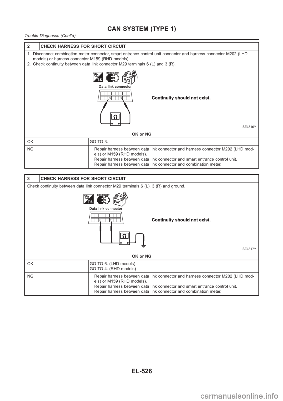
2 CHECK HARNESS FOR SHORT CIRCUIT
1. Disconnect combination meter connector, smart entrance control unit connector and harness connector M202 (LHD
models) or harness connector M159 (RHD models).
2. Check continuity between data link connector M29 terminals 6 (L) and 3 (R).
SEL816Y
OK or NG
OK GO TO 3.
NG Repair harness between data link connector and harness connector M202 (LHD mod-
els) or M159 (RHD models).
Repair harness between data link connector and smart entrance control unit.
Repair harness between data link connector and combination meter.
3 CHECK HARNESS FOR SHORT CIRCUIT
Check continuity between data link connector M29 terminals 6 (L), 3 (R) andground.
SEL817Y
OK or NG
OK GO TO 6. (LHD models)
GO TO 4. (RHD models)
NG Repair harness between data link connector and harness connector M202 (LHD mod-
els) or M159 (RHD models).
Repair harness between data link connector and smart entrance control unit.
Repair harness between data link connector and combination meter.
CAN SYSTEM (TYPE 1)
Trouble Diagnoses (Cont’d)
EL-526
Page 2864 of 3189
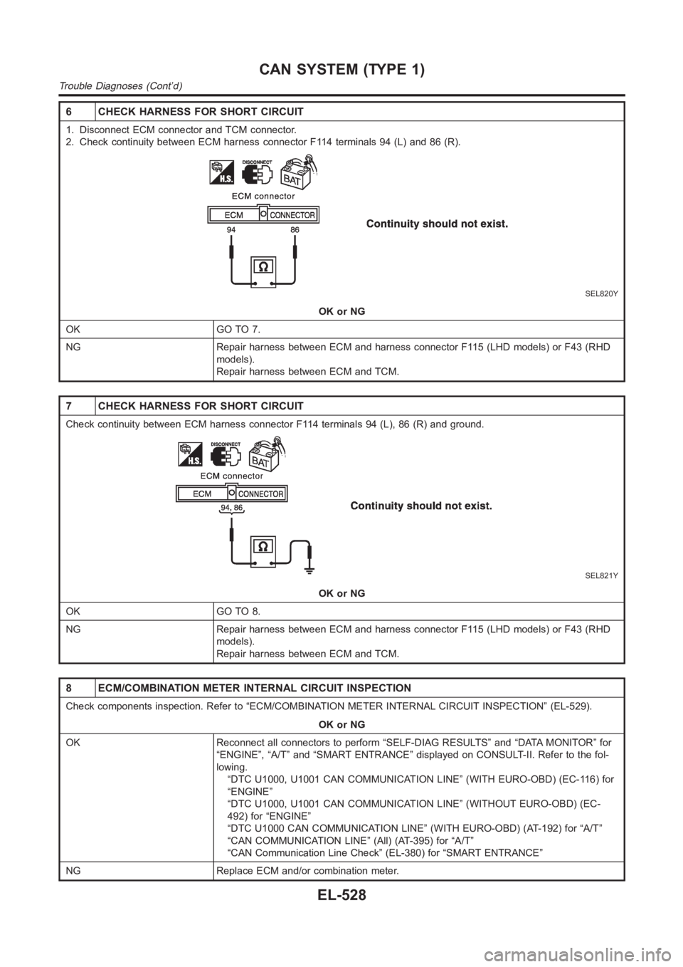
6 CHECK HARNESS FOR SHORT CIRCUIT
1. Disconnect ECM connector and TCM connector.
2. Check continuity between ECM harness connector F114 terminals 94 (L) and86(R).
SEL820Y
OK or NG
OK GO TO 7.
NG Repair harness between ECM and harness connector F115 (LHD models) or F43 (RHD
models).
Repair harness between ECM and TCM.
7 CHECK HARNESS FOR SHORT CIRCUIT
Check continuity between ECM harness connector F114 terminals 94 (L), 86 (R) and ground.
SEL821Y
OK or NG
OK GO TO 8.
NG Repair harness between ECM and harness connector F115 (LHD models) or F43 (RHD
models).
Repair harness between ECM and TCM.
8 ECM/COMBINATION METER INTERNAL CIRCUIT INSPECTION
Check components inspection. Refer to “ECM/COMBINATION METER INTERNAL CIRCUIT INSPECTION” (EL-529).
OK or NG
OK Reconnect all connectors to perform “SELF-DIAG RESULTS” and “DATA MONITOR” for
“ENGINE”, “A/T” and “SMART ENTRANCE” displayed on CONSULT-II. Refer to thefol-
lowing.
“DTC U1000, U1001 CAN COMMUNICATION LINE” (WITH EURO-OBD) (EC-116) for
“ENGINE”
“DTC U1000, U1001 CAN COMMUNICATION LINE” (WITHOUT EURO-OBD) (EC-
492) for “ENGINE”
“DTC U1000 CAN COMMUNICATION LINE” (WITH EURO-OBD) (AT-192) for “A/T”
“CAN COMMUNICATION LINE” (All) (AT-395) for “A/T”
“CAN Communication Line Check” (EL-380) for “SMART ENTRANCE”
NG Replace ECM and/or combination meter.
CAN SYSTEM (TYPE 1)
Trouble Diagnoses (Cont’d)
EL-528