Page 89 of 3189
![NISSAN ALMERA N16 2003 Electronic Repair Manual DRIVE BELTS
EM-11
[QG]
C
D
E
F
G
H
I
J
K
L
MA
EM
DRIVE BELTSPFP:02117
Checking Drive BeltsEBS00LPY
●Before inspecting the engine, make sure the engine has cooled down; wait approximately NISSAN ALMERA N16 2003 Electronic Repair Manual DRIVE BELTS
EM-11
[QG]
C
D
E
F
G
H
I
J
K
L
MA
EM
DRIVE BELTSPFP:02117
Checking Drive BeltsEBS00LPY
●Before inspecting the engine, make sure the engine has cooled down; wait approximately](/manual-img/5/57350/w960_57350-88.png)
DRIVE BELTS
EM-11
[QG]
C
D
E
F
G
H
I
J
K
L
MA
EM
DRIVE BELTSPFP:02117
Checking Drive BeltsEBS00LPY
●Before inspecting the engine, make sure the engine has cooled down; wait approximately 30 minutes
after the engine has been stopped.
●Visually inspect all belts for wear, damage, or cracks on contacting surfaces and edge areas.
●When measuring deflection, apply 98 N (10 kg, 22 lb) at the ▼ marked point.
CAUTION:
When measuring belt tension immediately after belt is installed, first set the tension to the standard.
Then, rotate crankshaft for more than two turns in order to eliminate variance in belt deflection
between the pulleys. Re-measure and adjust the tension to the standard.
PBIC0764E
Deflection adjustment Unit: mm (in)
Used belt
New belt
Limit After adjustment
AlternatorWithout air conditioner compressor 10.2 (0.402)6.5 - 7.0
(0.256 - 0.276)5.5 - 6.1
(0.217 - 0.240)
With air conditioner compressor 8.1 (0.319)5.3 - 5.7
(0.209 - 0.224)4.5 - 5.0
(0.177 - 0.197)
Power steering oil pump 7.1 (0.280)4.4 - 4.9
(0.173 - 0.193)3.9 - 4.4
(0.154 - 0.173)
Applied pushing force 98 N (10 kg, 22 lb)
Page 101 of 3189
![NISSAN ALMERA N16 2003 Electronic Repair Manual OIL PAN AND OIL STRAINER
EM-23
[QG]
C
D
E
F
G
H
I
J
K
L
MA
EM
7. Insert Tool (Seal cutter) between oil pan and cylinder block.
Slide tool by tapping on the side of the tool with a hammer.
NISSAN ALMERA N16 2003 Electronic Repair Manual OIL PAN AND OIL STRAINER
EM-23
[QG]
C
D
E
F
G
H
I
J
K
L
MA
EM
7. Insert Tool (Seal cutter) between oil pan and cylinder block.
Slide tool by tapping on the side of the tool with a hammer.](/manual-img/5/57350/w960_57350-100.png)
OIL PAN AND OIL STRAINER
EM-23
[QG]
C
D
E
F
G
H
I
J
K
L
MA
EM
7. Insert Tool (Seal cutter) between oil pan and cylinder block.
Slide tool by tapping on the side of the tool with a hammer.
Remove oil pan.
8. Remove oil strainer.
INSTALLATION
1. Install oil strainer.
NOTE:
Gasket and O-ring are not used for sealed area with oil pump.
2. Install oil pan drain plug.
●Referring to “Components”, install drain plug washer.
3. Apply a continuous bead of liquid gasket to position shown in figure.
Use Genuine Liquid Gasket or equivalent.
4. Tighten mounting nuts and bolts in order shown in figure.
●Install mounting nuts and bolts as follows.
5. Install center member.
Refer to ENGINE ASSEMBLY, EM-67, "
Removal and Installa-
tion" .
6. Install remaining parts in the reverse order of removal.
INSPECTION AFTER INSTALLATION
●Check for leakage of engine oil when engine is warmed.
●Pour engine oil or start engine at least 30 minutes after oil pan is installed.
SEM365EA
PBIC0549E
Mounting bolt:
[Shank length under
head 10 mm (0.39 in)]: Nos. 1 - 10, 13, 14
[Shank length under
head 12 mm (0.47 in)]: Nos. 11, 12
SEM072F
Page 131 of 3189
![NISSAN ALMERA N16 2003 Electronic Repair Manual TIMING CHAIN
EM-53
[QG]
C
D
E
F
G
H
I
J
K
L
MA
EM
h. Install front cover with mounting bolts temporarily so that front
cover will not move.
i. Press fit dowel pin into cylinder block through NISSAN ALMERA N16 2003 Electronic Repair Manual TIMING CHAIN
EM-53
[QG]
C
D
E
F
G
H
I
J
K
L
MA
EM
h. Install front cover with mounting bolts temporarily so that front
cover will not move.
i. Press fit dowel pin into cylinder block through](/manual-img/5/57350/w960_57350-130.png)
TIMING CHAIN
EM-53
[QG]
C
D
E
F
G
H
I
J
K
L
MA
EM
h. Install front cover with mounting bolts temporarily so that front
cover will not move.
i. Press fit dowel pin into cylinder block through front cover.
j. Tighten front cover mounting bolts temporarily.
●A [M6 x 20 mm (0.79 in)], B [M6 x 40 mm (1.57 in)], C [M8 x
70 mm (2.76 in)], D [M6 x 73 mm (2.87 in)]
●Bolt C also secures power steering pump adjusting bar.
●Bolt E [M6 x 12 mm (0.47 in)] is for installing power steering
pump adjusting bar.
k. Tighten cylinder head auxiliary bolts (M6) temporarily.
l. Tighten front cover mounting bolts and cylinder head auxiliary
bolts to specified torque.
4. Install oil pump drive spacer.
●When installing, align with flat of oil pump inner rotor.
●If they are not aligned, rotate inner rotor with a flat-bladed
screwdriver to align them.
CAUTION:
Be careful not to damage oil seal lips.
5. Install water pump pulley and idler pulley bracket assembly.
6. Install crankshaft pulley.
●When installing it, make sure that front oil seal lip is not inverted and garter spring is in position.
●For direction of mounting bolt washer, refer to “Component Parts Location”.
●With same procedure as “removal”, secure crankshaft, and tighten mounting bolts.
7. Install cylinder head front cover.
●Apply liquid gasket to cylinder head front cover.
●Use Genuine Liquid Gasket or equivalent.
8. Install engine front mounting bracket.
9. Install remaining parts in the reverse order of removal.
INSPECTION AFTER INSTALLATION
●In order to allow liquid gasket to be cured, perform inspection at least 30 minutes after the last step in
which parts sealed with liquid gasket are installed.
●With engine warmed up, check each part for engine oil leakage.
PBIC0564E
EMD0850D
PBIC0566E
PBIC0968E
Page 187 of 3189

Parts Requiring Angular TighteningNJEM0047Use an angle wrench for the final tightening of the following
engine parts:
a) Cylinder head bolts
b) Main bearing cap bolts
c) Connecting rod cap nuts
d) Crankshaft pulley bolt
Do not use a torque value for final tightening.
The torque value for these parts are for a preliminary step.
Ensure thread and seat surfaces are clean and coated with
engine oil.
SEM164F
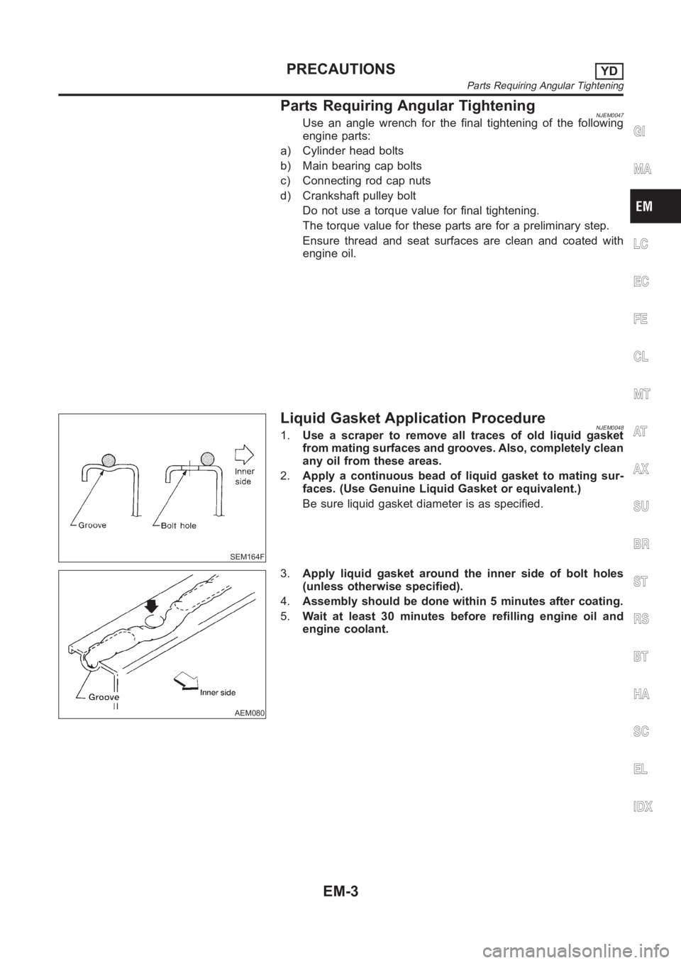
Liquid Gasket Application ProcedureNJEM00481.Use a scraper to remove all traces of old liquid gasket
from mating surfaces and grooves. Also, completely clean
any oil from these areas.
2.Apply a continuous bead of liquid gasket to mating sur-
faces. (Use Genuine Liquid Gasket or equivalent.)
Be sure liquid gasket diameter is as specified.
AEM080
3.Apply liquid gasket around the inner side of bolt holes
(unless otherwise specified).
4.Assembly should be done within 5 minutes after coating.
5.Wait at least 30 minutes before refilling engine oil and
engine coolant.
GI
MA
LC
EC
FE
CL
MT
AT
AX
SU
BR
ST
RS
BT
HA
SC
EL
IDX
PRECAUTIONSYD
Parts Requiring Angular Tightening
EM-3
Page 195 of 3189

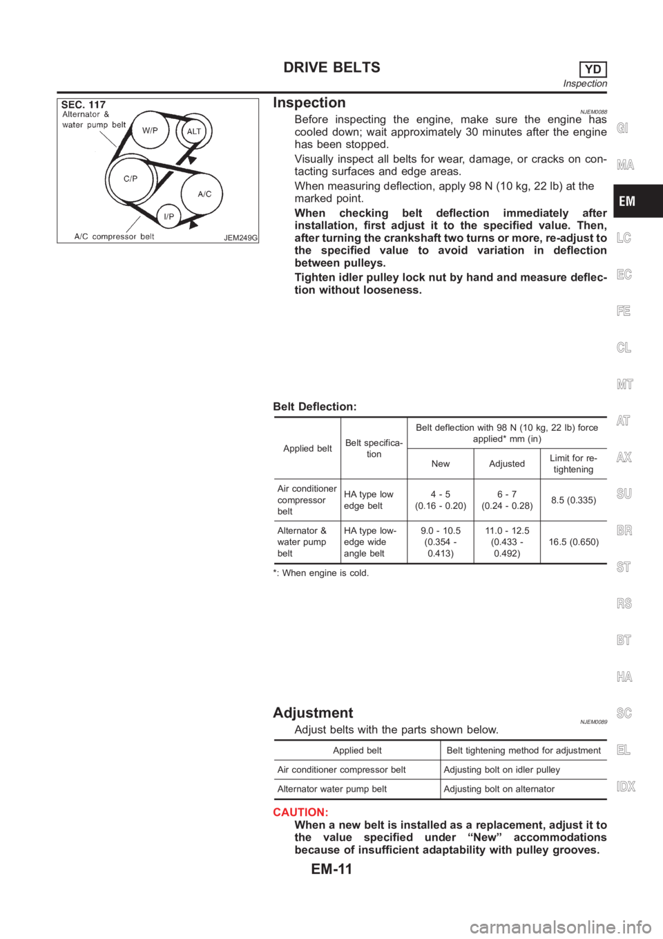
JEM249G
InspectionNJEM0088Before inspecting the engine, make sure the engine has
cooled down; wait approximately 30 minutes after the engine
has been stopped.
Visually inspect all belts for wear, damage, or cracks on con-
tacting surfaces and edge areas.
When measuring deflection, apply 98 N (10 kg, 22 lb) at the
marked point.
When checking belt deflection immediately after
installation, first adjust it to the specified value. Then,
after turning the crankshaft two turns or more, re-adjust to
the specified value to avoid variation in deflection
between pulleys.
Tighten idler pulley lock nut by hand and measure deflec-
tion without looseness.
Belt Deflection:
Applied beltBelt specifica-
tionBelt deflection with 98 N (10 kg, 22 lb) force
applied* mm (in)
New AdjustedLimit for re-
tightening
Air conditioner
compressor
beltHA type low
edge belt4-5
(0.16 - 0.20)6-7
(0.24 - 0.28)8.5 (0.335)
Alternator &
water pump
beltHA type low-
edge wide
angle belt9.0 - 10.5
(0.354 -
0.413)11 . 0 - 1 2 . 5
(0.433 -
0.492)16.5 (0.650)
*: When engine is cold.
AdjustmentNJEM0089Adjust belts with the parts shown below.
Applied belt Belt tightening method for adjustment
Air conditioner compressor belt Adjusting bolt on idler pulley
Alternator water pump belt Adjusting bolt on alternator
CAUTION:
When a new belt is installed as a replacement, adjust it to
the value specified under “New” accommodations
because of insufficient adaptability with pulley grooves.
GI
MA
LC
EC
FE
CL
MT
AT
AX
SU
BR
ST
RS
BT
HA
SC
EL
IDX
DRIVE BELTSYD
Inspection
EM-11
Page 201 of 3189

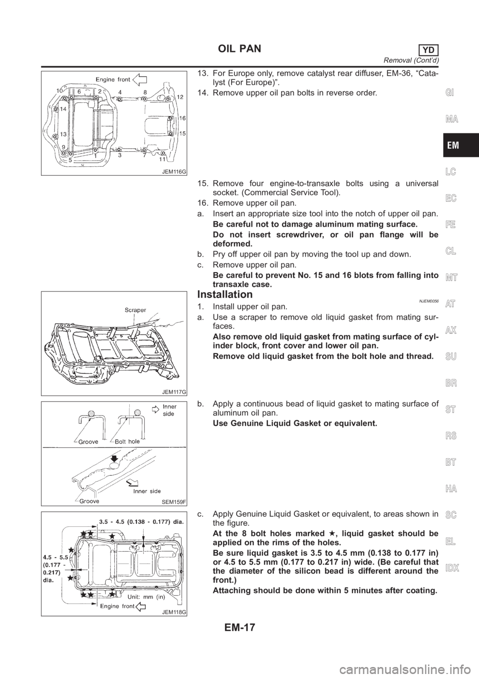
JEM116G
13. For Europe only, remove catalyst rear diffuser, EM-36, “Cata-
lyst (For Europe)”.
14. Remove upper oil pan bolts in reverse order.
15. Remove four engine-to-transaxle bolts using a universal
socket. (Commercial Service Tool).
16. Remove upper oil pan.
a. Insert an appropriate size tool into the notch of upper oil pan.
Be careful not to damage aluminum mating surface.
Do not insert screwdriver, or oil pan flange will be
deformed.
b. Pry off upper oil pan by moving the tool up and down.
c. Remove upper oil pan.
Be careful to prevent No. 15 and 16 blots from falling into
transaxle case.
JEM117G
InstallationNJEM00561. Install upper oil pan.
a. Use a scraper to remove old liquid gasket from mating sur-
faces.
Also remove old liquid gasket from mating surface of cyl-
inder block, front cover and lower oil pan.
Remove old liquid gasket from the bolt hole and thread.
SEM159F
b. Apply a continuous bead of liquid gasket to mating surface of
aluminum oil pan.
Use Genuine Liquid Gasket or equivalent.
JEM118G
c. Apply Genuine Liquid Gasket or equivalent, to areas shown in
the figure.
At the 8 bolt holes marked★, liquid gasket should be
applied on the rims of the holes.
Be sure liquid gasket is 3.5 to 4.5 mm (0.138 to 0.177 in)
or 4.5 to 5.5 mm (0.177 to 0.217 in) wide. (Be careful that
the diameter of the silicon bead is different around the
front.)
Attaching should be done within 5 minutes after coating.
GI
MA
LC
EC
FE
CL
MT
AT
AX
SU
BR
ST
RS
BT
HA
SC
EL
IDX
OIL PANYD
Removal (Cont’d)
EM-17
Page 202 of 3189

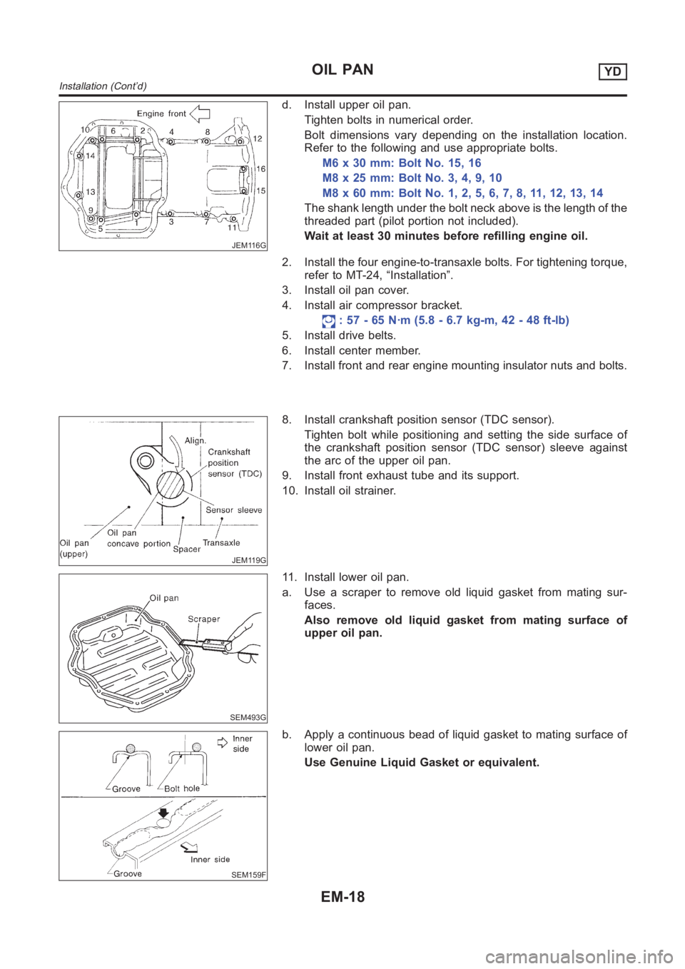
JEM116G
d. Install upper oil pan.
Tighten bolts in numerical order.
Bolt dimensions vary depending on the installation location.
Refer to the following and use appropriate bolts.
M6 x 30 mm: Bolt No. 15, 16
M8x25mm:BoltNo.3,4,9,10
M8x60mm:BoltNo.1,2,5,6,7,8,11,12,13,14
The shank length under the bolt neck above is the length of the
threaded part (pilot portion not included).
Wait at least 30 minutes before refilling engine oil.
2. Install the four engine-to-transaxle bolts. For tightening torque,
refer to MT-24, “Installation”.
3. Install oil pan cover.
4. Install air compressor bracket.
: 57 - 65 N·m (5.8 - 6.7 kg-m, 42 - 48 ft-lb)
5. Install drive belts.
6. Install center member.
7. Install front and rear engine mounting insulator nuts and bolts.
JEM119G
8. Install crankshaft position sensor (TDC sensor).
Tighten bolt while positioning and setting the side surface of
the crankshaft position sensor (TDC sensor) sleeve against
the arc of the upper oil pan.
9. Install front exhaust tube and its support.
10. Install oil strainer.
SEM493G
11. Install lower oil pan.
a. Use a scraper to remove old liquid gasket from mating sur-
faces.
Also remove old liquid gasket from mating surface of
upper oil pan.
SEM159F
b. Apply a continuous bead of liquid gasket to mating surface of
lower oil pan.
Use Genuine Liquid Gasket or equivalent.
OIL PANYD
Installation (Cont’d)
EM-18
Page 203 of 3189
SEM494G
Be sure liquid gasket is 3.5 to 4.5 mm (0.138 to 0.177 in)
wide.
Attaching should be done within 5 minutes after coating.
JEM114G
c. Install lower oil pan.
Tighten in numerical order shown in the figure.
Wait at least 30 minutes before refilling engine oil.
GI
MA
LC
EC
FE
CL
MT
AT
AX
SU
BR
ST
RS
BT
HA
SC
EL
IDX
OIL PANYD
Installation (Cont’d)
EM-19