2003 NISSAN ALMERA N16 transmission
[x] Cancel search: transmissionPage 756 of 3189
![NISSAN ALMERA N16 2003 Electronic Repair Manual EC-426
[QG (WITHOUT EURO-OBD)]
BASIC SERVICE PROCEDURE
●Transmission: Warmed-up
For A/T models with CONSULT-II, drive vehicle until “FLUID TEMP SE” in “DATA MONITOR” mode of “A/
T” syste NISSAN ALMERA N16 2003 Electronic Repair Manual EC-426
[QG (WITHOUT EURO-OBD)]
BASIC SERVICE PROCEDURE
●Transmission: Warmed-up
For A/T models with CONSULT-II, drive vehicle until “FLUID TEMP SE” in “DATA MONITOR” mode of “A/
T” syste](/manual-img/5/57350/w960_57350-755.png)
EC-426
[QG (WITHOUT EURO-OBD)]
BASIC SERVICE PROCEDURE
●Transmission: Warmed-up
For A/T models with CONSULT-II, drive vehicle until “FLUID TEMP SE” in “DATA MONITOR” mode of “A/
T” system indicates less than 0.9V.
For A/T models without CONSULT-II and M/T models, drive vehicle for 10 minutes.
OPERATION PROCEDURE
With CONSULT-II
1. Perform EC-425, "Accelerator Pedal Released Position Learning" .
2. Perform EC-425, "
Throttle Valve Closed Position Learning" .
3. Start engine and warm it up to normal operating temperature.
4. Check that all items listed under the topic “PREPARATION” (previously mentioned) are in good order.
5. Select “IDLE AIR VOL LEARN” in “WORK SUPPORT” mode.
6. Touch “START” and wait 20 seconds.
7. Make sure that “CMPLT” is displayed on CONSULT-II screen. If
“CMPLT” is not displayed, “Idle Air Volume Learning” will not be
carried out successfully. In this case, find the cause of the inci-
dent by referring to the “Diagnostic Procedure” below.
8. Rev up the engine two or three times and make sure that idle
speed and ignition timing are within the specifications.
Without CONSULT-II
NOTE:
●It is better to count the time accurately with a clock.
●It is impossible to switch the diagnostic mode when an accelerator pedal position sensor circuit
has a malfunction.
1. Perform EC-425, "
Accelerator Pedal Released Position Learning" .
2. Perform EC-425, "
Throttle Valve Closed Position Learning" .
3. Start engine and warm it up to normal operating temperature.
SEF217Z
SEF454Y
ITEM SPECIFICATION
Idle speed M/T: 700±50 rpm
A/T: 800±50 rpm (in “P” or “N” position)
Ignition timing M/T: 8±5° BTDC
A/T: 10±5° BTDC (in “P” or “N” position)
MBIB0238E
Page 768 of 3189
![NISSAN ALMERA N16 2003 Electronic Repair Manual EC-438
[QG (WITHOUT EURO-OBD)]
TROUBLE DIAGNOSIS
Description for Work Flow
STEP DESCRIPTION
STEP IGet detailed information about the conditions and the environment when the incident/symptom occurred u NISSAN ALMERA N16 2003 Electronic Repair Manual EC-438
[QG (WITHOUT EURO-OBD)]
TROUBLE DIAGNOSIS
Description for Work Flow
STEP DESCRIPTION
STEP IGet detailed information about the conditions and the environment when the incident/symptom occurred u](/manual-img/5/57350/w960_57350-767.png)
EC-438
[QG (WITHOUT EURO-OBD)]
TROUBLE DIAGNOSIS
Description for Work Flow
STEP DESCRIPTION
STEP IGet detailed information about the conditions and the environment when the incident/symptom occurred using the
“DIAGNOSTIC WORK SHEET”, EC-440
.
STEP IIBefore confirming the concern, check and write down (print out using CONSULT-II) the (1st trip) DTC and the (1st
trip) freeze frame data, then erase the DTC and the data. (Refer to EC-430
.) The (1st trip) DTC and the (1st trip)
freeze frame data can be used when duplicating the incident at STEP III & IV.
If the incident cannot be verified, perform EC-485, "
TROUBLE DIAGNOSIS FOR INTERMITTENT INCIDENT" .
Study the relationship between the cause, specified by (1st trip) DTC, and the symptom described by the customer.
(The “Symptom Matrix Chart” will be useful. See EC-448
.)
Also check related service bulletins for information.
STEP IIITry to confirm the symptom and under what conditions the incident occurs.
The “DIAGNOSTIC WORK SHEET” and the freeze frame data are useful to verify the incident. Connect CONSULT-II
to the vehicle in DATA MONITOR (AUTO TRIG) mode and check real time diagnosis results.
If the incident cannot be verified, perform EC-485, "
TROUBLE DIAGNOSIS FOR INTERMITTENT INCIDENT" .
If the malfunction code is detected, skip STEP IV and perform STEP V.
STEP IVTry to detect the (1st trip) DTC by driving in (or performing) the “DTC Confirmation Procedure”. Check and read the
(1st trip) DTC and (1st trip) freeze frame data by using CONSULT-II or GST.
During the (1st trip) DTC verification, be sure to connect CONSULT-II to the vehicle in DATA MONITOR (AUTO TRIG)
mode and check real time diagnosis results.
If the incident cannot be verified, perform EC-485, "
TROUBLE DIAGNOSIS FOR INTERMITTENT INCIDENT" .
In case the “DTC Confirmation Procedure” is not available, perform the “Overall Function Check” instead. The (1st
trip) DTC cannot be displayed by this check, however, this simplified “check” is an effective alternative.
The “NG” result of the “Overall Function Check” is the same as the (1st trip) DTC detection.
STEP VTake the appropriate action based on the results of STEP I through IV.
If the malfunction code is indicated, proceed to TROUBLE DIAGNOSIS FOR DTC PXXXX.
If the normal code is indicated, proceed to the BASIC INSPECTION. (Refer to EC-443
.) If COSULT-II is available,
perform “DATA MONITOR (SPEC)” mode with CONSULT-II and proceed to the “TOROUBLE DIAGNOSIS – SPECI-
FICATION VALUE”. (Refer to EC-481
.) (If malfunction is detected, proceed to “PERAIR/REPLACE”.) Then perform
inspections according to the Symptom Matrix Chart. (Refer to EC-448
.)
STEP VIIdentify where to begin diagnosis based on the relationship study between symptom and possible causes. Inspect the
system for mechanical binding, loose connectors or wiring damage using (tracing) “Harness Layouts”.
Gently shake the related connectors, components or wiring harness with CONSULT-II set in “DATA MONITOR
(AUTO TRIG)” mode.
Check the voltage of the related ECM terminals or monitor the output data from the related sensors with CONSULT-II.
Refer to EC-458
, EC-475 .
The “Diagnostic Procedure” in EC section contains a description based on open circuit inspection. A short circuit
inspection is also required for the circuit check in the Diagnostic Procedure. For details, refer to “Circuit Inspection” in
GI-22.
Repair or replace the malfunction parts.
If malfunctioning part cannot be detected, perform EC-485, "
TROUBLE DIAGNOSIS FOR INTERMITTENT INCI-
DENT" .
STEP VIIOnce you have repaired the circuit or replaced a component, you need to run the engine in the same conditions and
circumstances which resulted in the customer's initial complaint.
Perform the “DTC Confirmation Procedure” and confirm the normal code [DTC No. P0000] is detected. If the incident
is still detected in the final check, perform STEP VI by using a method different from the previous one.
Before returning the vehicle to the customer, be sure to erase the unnecessary (already fixed) (1st trip) DTC in ECM
and TCM (Transmission control module). (Refer to EC-430, "
HOW TO ERASE EMISSION-RELATED DIAGNOSTIC
INFORMATION" .)
Page 811 of 3189
![NISSAN ALMERA N16 2003 Electronic Repair Manual TROUBLE DIAGNOSIS - SPECIFICATION VALUE
EC-481
[QG (WITHOUT EURO-OBD)]
C
D
E
F
G
H
I
J
K
L
MA
EC
TROUBLE DIAGNOSIS - SPECIFICATION VALUEPFP:00031
DescriptionEBS00KF3
The specification (SP) value indic NISSAN ALMERA N16 2003 Electronic Repair Manual TROUBLE DIAGNOSIS - SPECIFICATION VALUE
EC-481
[QG (WITHOUT EURO-OBD)]
C
D
E
F
G
H
I
J
K
L
MA
EC
TROUBLE DIAGNOSIS - SPECIFICATION VALUEPFP:00031
DescriptionEBS00KF3
The specification (SP) value indic](/manual-img/5/57350/w960_57350-810.png)
TROUBLE DIAGNOSIS - SPECIFICATION VALUE
EC-481
[QG (WITHOUT EURO-OBD)]
C
D
E
F
G
H
I
J
K
L
MA
EC
TROUBLE DIAGNOSIS - SPECIFICATION VALUEPFP:00031
DescriptionEBS00KF3
The specification (SP) value indicates the tolerance of the value that is displayed in “DATA MONITOR (SPEC)”
mode of CONSULT-II during normal operation of the Engine Control System. When the value in “DATA MONI-
TOR (SPEC)” mode is within the SP value, the Engine Control System is confirmed OK. When the value in
“DATA MONITOR (SPEC)” mode is NOT within the SP value, the Engine Control System may have one or
more malfunctions.
The SP value is used to detect malfunctions that may affect the Engine Control System, but will not light the
MI.
The SP value will be displayed for the following three items:
●B/FUEL SCHDL (The fuel injection pulse width programmed into ECM prior to any learned on board cor-
rection)
●A/F ALPHA-B1 (The mean value of air-fuel ratio feedback correction factor per cycle)
●MAS A/F SE-B1 (The signal voltage of the mass air flow sensor)
Testing ConditionEBS00KF4
●Vehicle driven distance: More than 5,000 km (3,017 miles)
●Barometric pressure: 98.3 - 104.3 kPa (0.983 - 1.043 bar, 1.003 - 1.064 kg/cm2 , 14.25 - 15.12 psi)
●Atmospheric temperature: 20 - 30°C (68 - 86°F)
●Engine coolant temperature: 75 - 95°C (167 - 203°F)
●Transmission: Warmed-up*1
●Electrical load: Not applied*2
●Engine speed: Idle
*1: For A/T models, after the engine is warmed up to normal operating temperature, drive vehicle until “FLUID
TEMP SE” (A/T fluid temperature sensor signal) indicates more than 60°C (140°F).
For M/T models, after the engine is warmed up to normal operating temperature, drive vehicle for 5 minutes.
*2: Rear window defogger switch, air conditioner switch, lighting switch are “OFF”. Steering wheel is straight
ahead.
Inspection ProcedureEBS00KF5
NOTE:
Perform “DATA MONITOR (SPEC)” mode in maximum scale display.
1. Perform EC-443, "
Basic Inspection" .
2. Confirm that the testing conditions indicated above are met.
3. Select “B/FUEL SCHDL”, “A/F ALPHA-B1” and “MAS A/F SE-
B1” in “DATA MONITOR (SPEC)” mode with CONSULT-II.
4. Make sure that monitor items are within the SP value.
5. If NG, go to EC-482, "
Diagnostic Procedure" .
SEF601Z
Page 822 of 3189
![NISSAN ALMERA N16 2003 Electronic Repair Manual EC-492
[QG (WITHOUT EURO-OBD)]
DTC U1000, U1001 CAN COMMUNICATION LINE
DTC U1000, U1001 CAN COMMUNICATION LINE
PFP:23710
DescriptionEBS00KFC
CAN (Controller Area Network) is a serial communication lin NISSAN ALMERA N16 2003 Electronic Repair Manual EC-492
[QG (WITHOUT EURO-OBD)]
DTC U1000, U1001 CAN COMMUNICATION LINE
DTC U1000, U1001 CAN COMMUNICATION LINE
PFP:23710
DescriptionEBS00KFC
CAN (Controller Area Network) is a serial communication lin](/manual-img/5/57350/w960_57350-821.png)
EC-492
[QG (WITHOUT EURO-OBD)]
DTC U1000, U1001 CAN COMMUNICATION LINE
DTC U1000, U1001 CAN COMMUNICATION LINE
PFP:23710
DescriptionEBS00KFC
CAN (Controller Area Network) is a serial communication line for real time application. It is an on-vehicle mul-
tiplex communication line with high data communication speed and excellent error detection ability. Many elec-
tronic control units are equipped onto a vehicle, and each control unit shares information and links with other
control units during operation (not independent). In CAN communication, control units are connected with 2
communication lines (CAN H line, CAN L line) allowing a high rate of information transmission with less wiring.
Each control unit transmits/receives data but selectively reads required data only.
On Board Diagnosis LogicEBS00KFD
The MI will not light up for this diagnosis.
*1: This self-diagnosis has the one trip detection logic.
*2: The MI will not light up for this diagnosis.
DTC Confirmation ProcedureEBS00KFE
1. Turn ignition switch “ON” and wait at least 3 seconds.
2. Select “DATA MONITOR” mode with CONSULT-II.
3. If 1st trip DTC is detected, go to EC-494, "
Diagnostic Procedure" .
DTC No.Trouble diagnosis
nameDTC detecting condition Possible cause
U1000*
1
1000*1CAN communication
line
●ECM cannot communicate to other control
units.
●ECM cannot communicate for more than the
specified time.
●Harness or connectors
(CAN communication line is open or
shorted.) U1001*
2
1001 *2
Page 1275 of 3189

SFE642A
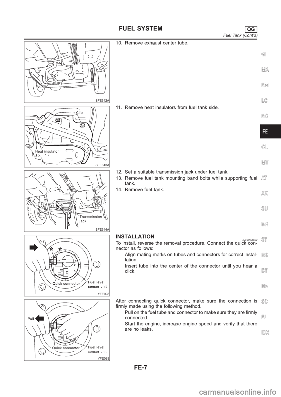
10. Remove exhaust center tube.
SFE643A
11. Remove heat insulators from fuel tank side.
SFE644A
12. Set a suitable transmission jack under fuel tank.
13. Remove fuel tank mounting band bolts while supporting fuel
tank.
14. Remove fuel tank.
YFE028
INSTALLATIONNJFE0006S02To install, reverse the removal procedure. Connect the quick con-
nector as follows:
Align mating marks on tubes and connectors for correct instal-
lation.
Insert tube into the center of the connector until you hear a
click.
YFE029
After connecting quick connector, make sure the connection is
firmly made using the following method.
Pull on the fuel tube and connector to make sure they are firmly
connected.
Start the engine, increase engine speed and verify that there
are no leaks.
GI
MA
EM
LC
EC
CL
MT
AT
AX
SU
BR
ST
RS
BT
HA
SC
EL
IDX
FUEL SYSTEMQG
Fuel Tank (Cont’d)
FE-7
Page 1288 of 3189

SFE602A
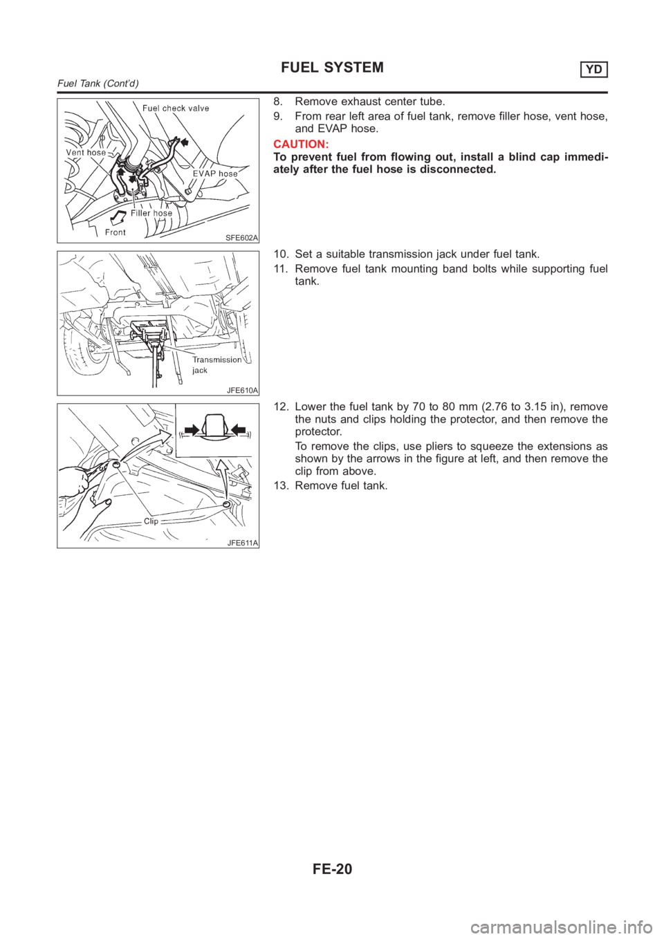
8. Remove exhaust center tube.
9. From rear left area of fuel tank, remove filler hose, vent hose,
and EVAP hose.
CAUTION:
To prevent fuel from flowing out, install a blind cap immedi-
ately after the fuel hose is disconnected.
JFE610A
10. Set a suitable transmission jack under fuel tank.
11. Remove fuel tank mounting band bolts while supporting fuel
tank.
JFE611A
12. Lower the fuel tank by 70 to 80 mm (2.76 to 3.15 in), remove
the nuts and clips holding the protector, and then remove the
protector.
To remove the clips, use pliers to squeeze the extensions as
shown by the arrows in the figure at left, and then remove the
clip from above.
13. Remove fuel tank.
FUEL SYSTEMYD
Fuel Tank (Cont’d)
FE-20
Page 1290 of 3189

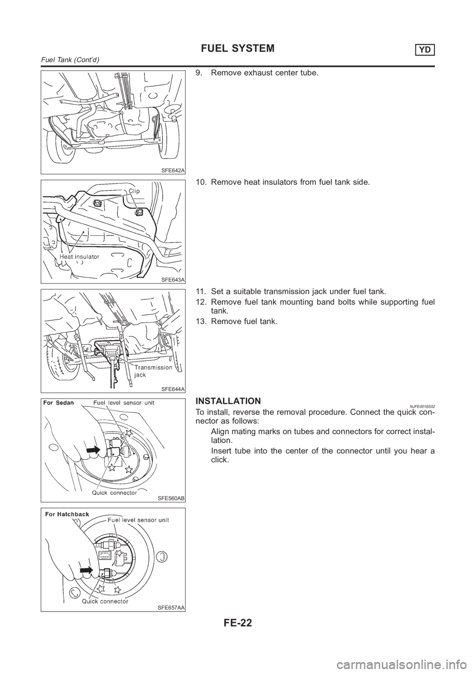
SFE642A
9. Remove exhaust center tube.
SFE643A
10. Remove heat insulators from fuel tank side.
SFE644A
11. Set a suitable transmission jack under fuel tank.
12. Remove fuel tank mounting band bolts while supporting fuel
tank.
13. Remove fuel tank.
SFE560AB
SFE657AA
INSTALLATIONNJFE0016S02To install, reverse the removal procedure. Connect the quick con-
nector as follows:
Align mating marks on tubes and connectors for correct instal-
lation.
Insert tube into the center of the connector until you hear a
click.
FUEL SYSTEMYD
Fuel Tank (Cont’d)
FE-22
Page 1350 of 3189

NJMT0039
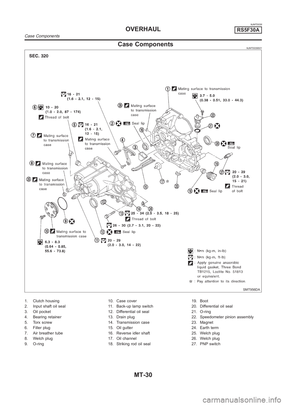
Case ComponentsNJMT0039S01
SMT956DA
1. Clutch housing
2. Input shaft oil seal
3. Oil pocket
4. Bearing retainer
5. Torx screw
6. Filler plug
7. Air breather tube
8. Welch plug
9. O-ring10. Case cover
11. Back-up lamp switch
12. Differential oil seal
13. Drain plug
14. Transmission case
15. Oil gutter
16. Reverse idler shaft
17. Oil channel
18. Striking rod oil seal19. Boot
20. Differential oil seal
21. O-ring
22. Speedometer pinion assembly
23. Magnet
24. Earth term
25. Welch plug
26. Welch plug
27. PNP switch
OVERHAULRS5F30A
Case Components
MT-30