2003 NISSAN ALMERA N16 transmission
[x] Cancel search: transmissionPage 1431 of 3189
NJMT0022
Input Shaft End Play and Differential Side
Bearing Preload
NJMT0022S01If any of the following parts are replaced, adjust input shaft end
play.
Input shaft
Input shaft bearing
Clutch housing
Transmission case
If any of the following parts are replaced, adjust differential side
bearing preload.
Differential case
Differential side bearing
Clutch housing
Transmission case
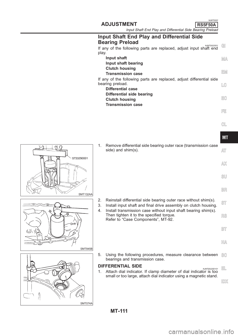
SMT132AA
1. Remove differential side bearing outer race (transmission case
side) and shim(s).
SMT845B
2. Reinstall differential side bearing outer race without shim(s).
3. Install input shaft and final drive assembly on clutch housing.
4. Install transmission case without input shaft bearing shim(s).
Then tighten it to the specified torque.
Refer to “Case Components”, MT-92.
SMT074A
5. Using the following procedures, measure clearance between
bearings and transmission case.
DIFFERENTIAL SIDENJMT0022S01011. Attach dial indicator. If clamp diameter of dial indicator is too
small or too large, attach dial indicator using a magnetic stand.
GI
MA
EM
LC
EC
FE
CL
AT
AX
SU
BR
ST
RS
BT
HA
SC
EL
IDX
ADJUSTMENTRS5F50A
Input Shaft End Play and Differential Side Bearing Preload
MT-111
Page 1432 of 3189
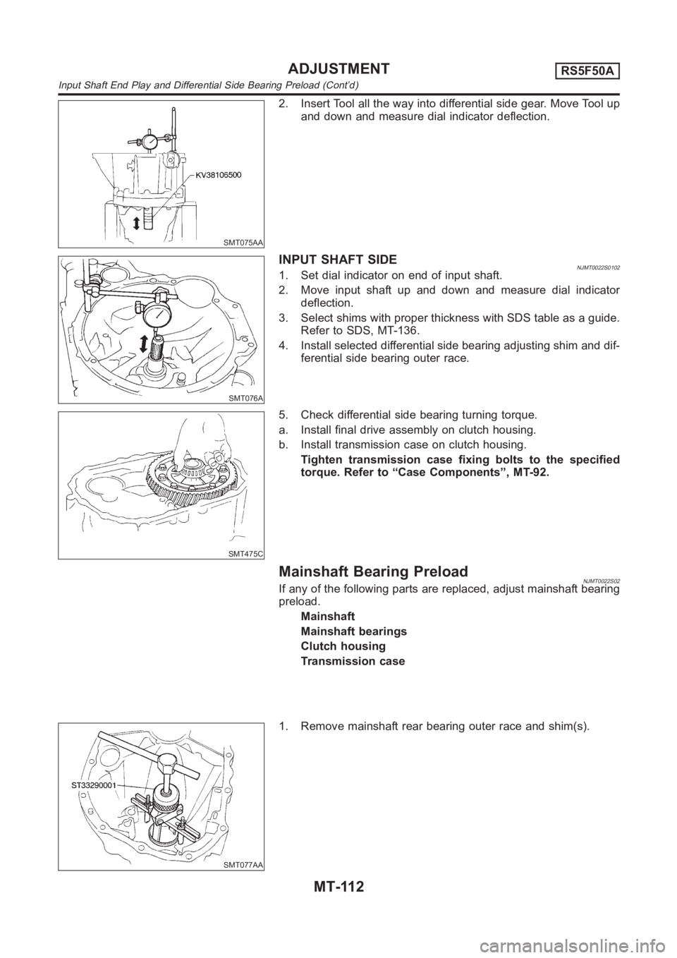
SMT075AA
2. Insert Tool all the way into differential side gear. Move Tool up
and down and measure dial indicator deflection.
SMT076A
INPUTSHAFTSIDENJMT0022S01021. Set dial indicator on end of input shaft.
2. Move input shaft up and down and measure dial indicator
deflection.
3. Select shims with proper thickness with SDS table as a guide.
Refer to SDS, MT-136.
4. Install selected differential side bearing adjusting shim and dif-
ferential side bearing outer race.
SMT475C
5. Check differential side bearing turning torque.
a. Install final drive assembly on clutch housing.
b. Install transmission case on clutch housing.
Tighten transmission case fixing bolts to the specified
torque. Refer to “Case Components”, MT-92.
Mainshaft Bearing PreloadNJMT0022S02If any of the following parts are replaced, adjust mainshaft bearing
preload.
Mainshaft
Mainshaft bearings
Clutch housing
Transmission case
SMT077AA
1. Remove mainshaft rear bearing outer race and shim(s).
ADJUSTMENTRS5F50A
Input Shaft End Play and Differential Side Bearing Preload (Cont’d)
MT-112
Page 1433 of 3189
SMT644AA
2. Reinstall mainshaft rear bearing outer race without shims.
3. Clean mating surfaces of clutch housing and transmission
case with solvent.
4. Install mainshaft and mainshaft front bearing outer race into
transmission case. Turn mainshaft while holding bearing outer
race so that bearings are properly seated.
SMT078A
SMT079A
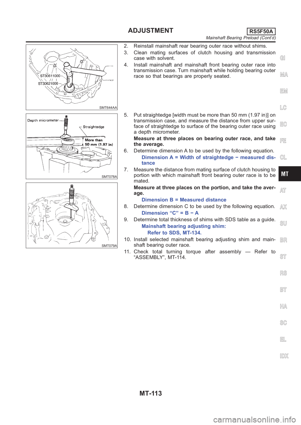
5. Put straightedge [width must be more than 50 mm (1.97 in)] on
transmission case, and measure the distance from upper sur-
face of straightedge to surface of the bearing outer race using
a depth micrometer.
Measure at three places on bearing outer race, and take
the average.
6. Determine dimension A to be used by the following equation.
Dimension A = Width of straightedge − measured dis-
tance
7. Measure the distance from mating surface of clutch housing to
portion with which mainshaft front bearing outer race is to be
mated.
Measure at three places on the portion, and take the aver-
age.
Dimension B = Measured distance
8. Determine dimension C to be used by the following equation.
Dimension “C” = B − A
9. Determine total thickness of shims with SDS table as a guide.
Mainshaft bearing adjusting shim:
Refer to SDS, MT-134.
10. Install selected mainshaft bearing adjusting shim and main-
shaft bearing outer race.
11. Check total turning torque after assembly — Refer to
“ASSEMBLY”, MT-114.
GI
MA
EM
LC
EC
FE
CL
AT
AX
SU
BR
ST
RS
BT
HA
SC
EL
IDX
ADJUSTMENTRS5F50A
Mainshaft Bearing Preload (Cont’d)
MT-113
Page 1437 of 3189
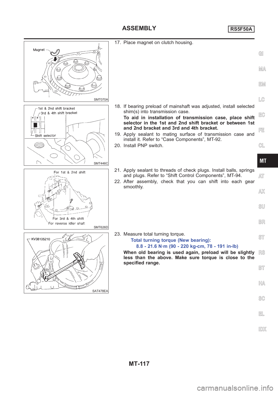
SMT070A
17. Place magnet on clutch housing.
SMT446C
18. If bearing preload of mainshaft was adjusted, install selected
shim(s) into transmission case.
To aid in installation of transmission case, place shift
selector in the 1st and 2nd shift bracket or between 1st
and 2nd bracket and 3rd and 4th bracket.
19. Apply sealant to mating surface of transmission case and
install it. Refer to “Case Components”, MT-92.
20. Install PNP switch.
SMT626D
21. Apply sealant to threads of check plugs. Install balls, springs
and plugs. Refer to “Shift Control Components”, MT-94.
22. After assembly, check that you can shift into each gear
smoothly.
SAT478EA
23. Measure total turning torque.
Total turning torque (New bearing):
8.8 - 21.6 N·m (90 - 220 kg-cm, 78 - 191 in-lb)
When old bearing is used again, preload will be slightly
less than the above. Make sure torque is close to the
specified range.
GI
MA
EM
LC
EC
FE
CL
AT
AX
SU
BR
ST
RS
BT
HA
SC
EL
IDX
ASSEMBLYRS5F50A
MT-117
Page 1457 of 3189
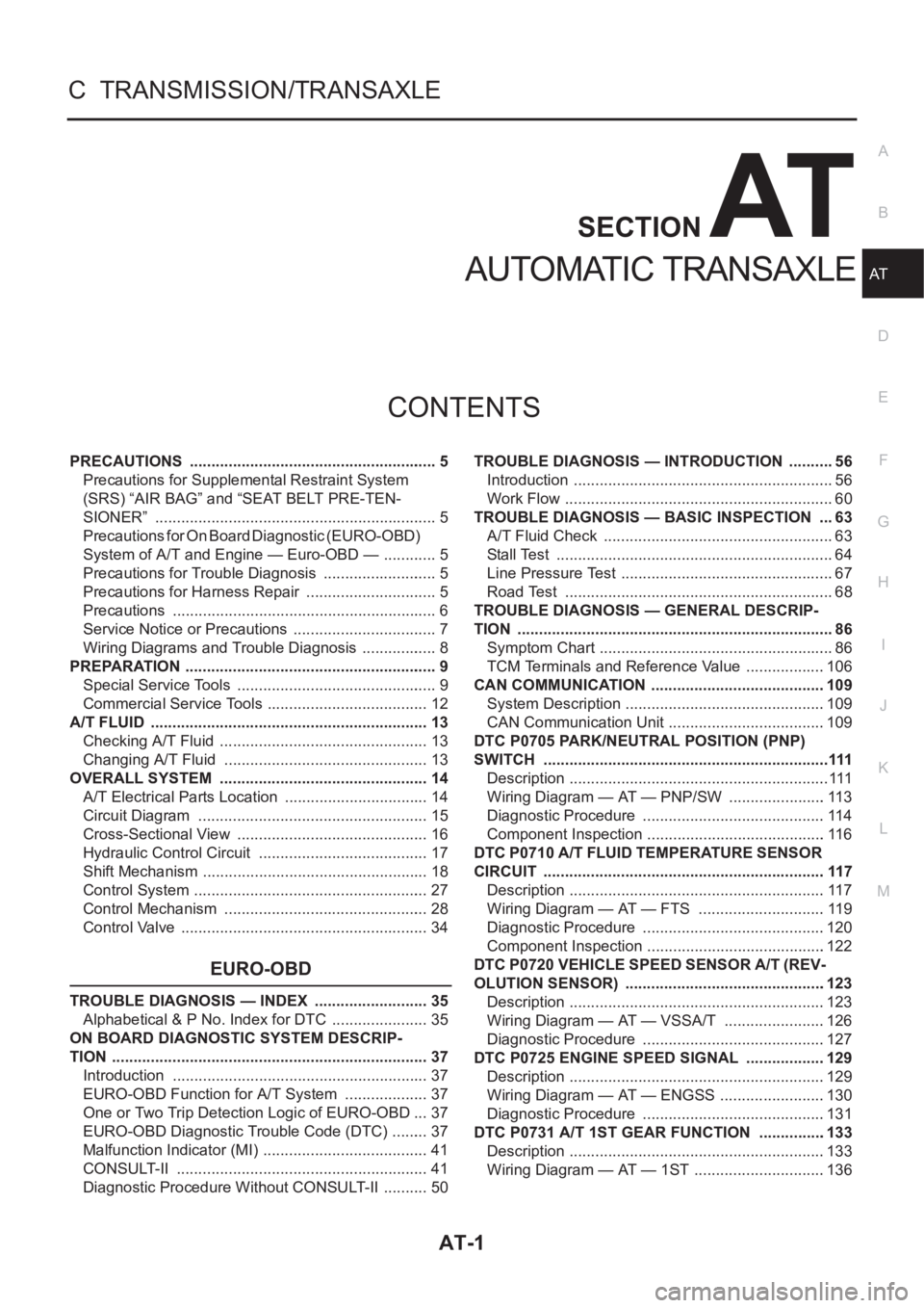
AT-1
AUTOMATIC TRANSAXLE
C TRANSMISSION/TRANSAXLE
CONTENTS
D
E
F
G
H
I
J
K
L
M
SECTION
A
B
AT
AUTOMATIC TRANSAXLE
PRECAUTIONS .......................................................... 5
Precautions for Supplemental Restraint System
(SRS) “AIR BAG” and “SEAT BELT PRE-TEN-
SIONER” .................................................................. 5
Precautions for On Board Diagnostic (EURO-OBD)
System of A/T and Engine — Euro-OBD — ............. 5
Precautions for Trouble Diagnosis ........................... 5
Precautions for Harness Repair ............................... 5
Precautions .............................................................. 6
Service Notice or Precautions .................................. 7
Wiring Diagrams and Trouble Diagnosis .................. 8
PREPARATION ........................................................... 9
Special Service Tools ............................................... 9
Commercial Service Tools ...................................... 12
A/T FLUID ................................................................. 13
Checking A/T Fluid ................................................. 13
Changing A/T Fluid ............................................. ... 13
OVERALL SYSTEM ................................................. 14
A/T Electrical Parts Location .................................. 14
Circuit Diagram ...................................................... 15
Cross-Sectional View ............................................. 16
Hydraulic Control Circuit ........................................ 17
Shift Mechanism ..................................................... 18
Control System ....................................................... 27
Control Mechanism ................................................ 28
Control Valve .......................................................... 34
EURO-OBD
TROUBLE DIAGNOSIS — INDEX ........................... 35
Alphabetical & P No. Index for DTC ....................... 35
ON BOARD DIAGNOSTIC SYSTEM DESCRIP-
TION .......................................................................... 37
Introduction ............................................................ 37
EURO-OBD Function for A/T System .................... 37
One or Two Trip Detection Logic of EURO-OBD ... 37
EURO-OBD Diagnostic Trouble Code (DTC) ......... 37
Malfunction Indicator (MI) ....................................... 41
CONSULT-II ........................................................... 41
Diagnostic Procedure Without CONSULT-II ........... 50TROUBLE DIAGNOSIS — INTRODUCTION ........... 56
Introduction ............................................................. 56
Work Flow ............................................................... 60
TROUBLE DIAGNOSIS — BASIC INSPECTION .... 63
A/T Fluid Check ...................................................... 63
Stall Test ................................................................. 64
Line Pressure Test .................................................. 67
Road Test ............................................................... 68
TROUBLE DIAGNOSIS — GENERAL DESCRIP-
TION .......................................................................... 86
Symptom Chart ....................................................... 86
TCM Terminals and Reference Value ...................106
CAN COMMUNICATION .........................................109
System Description ...............................................109
CAN Communication Unit .....................................109
DTC P0705 PARK/NEUTRAL POSITION (PNP)
SWITCH ...................................................................111
Description .............................................................111
Wiring Diagram — AT — PNP/SW .......................113
Diagnostic Procedure ...........................................114
Component Inspection ..........................................116
DTC P0710 A/T FLUID TEMPERATURE SENSOR
CIRCUIT ..................................................................117
Description ............................................................117
Wiring Diagram — AT — FTS ..............................119
Diagnostic Procedure ...........................................120
Component Inspection ..........................................122
DTC P0720 VEHICLE SPEED SENSOR A/T (REV-
OLUTION SENSOR) ...............................................123
Description ............................................................123
Wiring Diagram — AT — VSSA/T ........................126
Diagnostic Procedure ...........................................127
DTC P0725 ENGINE SPEED SIGNAL ...................129
Description ............................................................129
Wiring Diagram — AT — ENGSS .........................130
Diagnostic Procedure ..........................................
.131
DTC P0731 A/T 1ST GEAR FUNCTION ................133
Description ............................................................133
Wiring Diagram — AT — 1ST ...............................136
Page 1466 of 3189
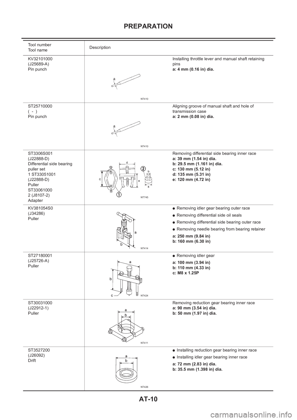
AT-10
PREPARATION
KV32101000
(J25689-A)
Pin punch Installing throttle lever and manual shaft retaining
pins
a: 4 mm (0.16 in) dia.
ST25710000
( - )
Pin punch Aligning groove of manual shaft and hole of
transmission case
a: 2 mm (0.08 in) dia.
ST3306S001
(J22888-D)
Differential side bearing
puller set
1 ST33051001
(J22888-D)
Puller
ST33061000
2 (J8107-2)
AdapterRemoving differential side bearing inner race
a: 39 mm (1.54 in) dia.
b: 29.5 mm (1.161 in) dia.
c: 130 mm (5.12 in)
d: 135 mm (5.31 in)
e: 120 mm (4.72 in)
KV381054S0
(J34286)
Puller
●Removing idler gear bearing outer race
●Removing differential side oil seals
●Removing differential side bearing outer race
●Removing needle bearing from bearing retainer
a: 250 mm (9.84 in)
b: 160 mm (6.30 in)
ST27180001
(J25726-A)
Puller
●Removing idler gear
a: 100 mm (3.94 in)
b: 110 mm (4.33 in)
c: M8 x 1.25P
ST30031000
(J22912-1)
Puller Removing reduction gear bearing inner race
a: 90 mm (3.54 in) dia.
b: 50 mm (1.97 in) dia.
ST3527200
(J26092)
Drift
●Installing reduction gear bearing inner race
●Installing idler gear bearing inner race
a: 72 mm (2.83 in) dia.
b: 35.5 mm (1.398 in) dia. Tool number
Tool nameDescription
NT410
NT410
NT745
NT414
NT424
NT411
NT426
Page 1475 of 3189
OVERALL SYSTEM
AT-19
D
E
F
G
H
I
J
K
L
MA
B
AT
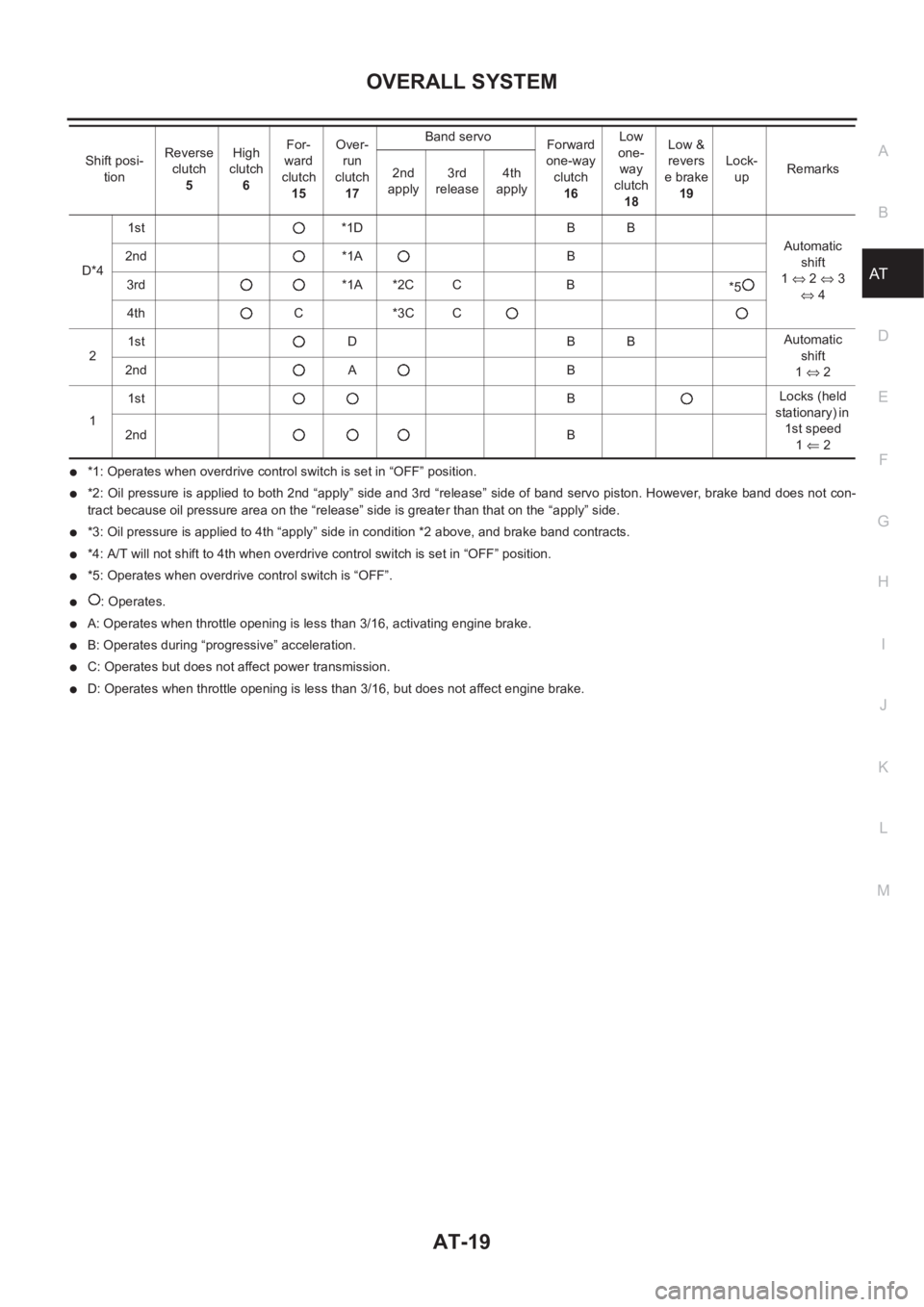
●*1: Operates when overdrive control switch is set in “OFF” position.
●*2: Oil pressure is applied to both 2nd “apply” side and 3rd “release” side of band servo piston. However, brake band does not con-
tract because oil pressure area on the “release” side is greater than that on the “apply” side.
●*3: Oil pressure is applied to 4th “apply” side in condition *2 above, and brake band contracts.
●*4: A/T will not shift to 4th when overdrive control switch is set in “OFF” position.
●*5: Operates when overdrive control switch is “OFF”.
●: Operates.
●A: Operates when throttle opening is less than 3/16, activating engine brake.
●B: Operates during “progressive” acceleration.
●C: Operates but does not affect power transmission.
●D: Operates when throttle opening is less than 3/16, but does not affect engine brake. D*41st *1D B B
Automatic
shift
1⇔ 2 ⇔ 3
⇔ 4 2nd *1A B
3rd *1A *2C C B
*5
4th C *3C C
21st D B BAutomatic
shift
1⇔ 2 2nd A B
11stBLocks (held
stationary) in
1st speed
1⇐ 2 2ndB Shift posi-
tionReverse
clutch
5High
clutch
6For-
ward
clutch
15Over-
run
clutch
17Band servo
Forward
one-way
clutch
16Low
one-
way
clutch
18Low &
revers
e brake
19Lock-
upRemarks
2nd
apply3rd
release4th
apply
Page 1476 of 3189
AT-20
OVERALL SYSTEM
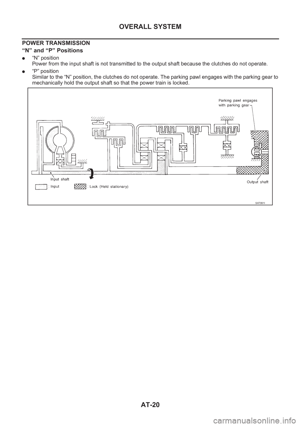
POWER TRANSMISSION
“N” and “P” Positions
●“N” position
Power from the input shaft is not transmitted to the output shaft because the clutches do not operate.
●“P” position
Similar to the “N” position, the clutches do not operate. The parking pawl engages with the parking gear to
mechanically hold the output shaft so that the power train is locked.
SAT991I