Page 2943 of 3189

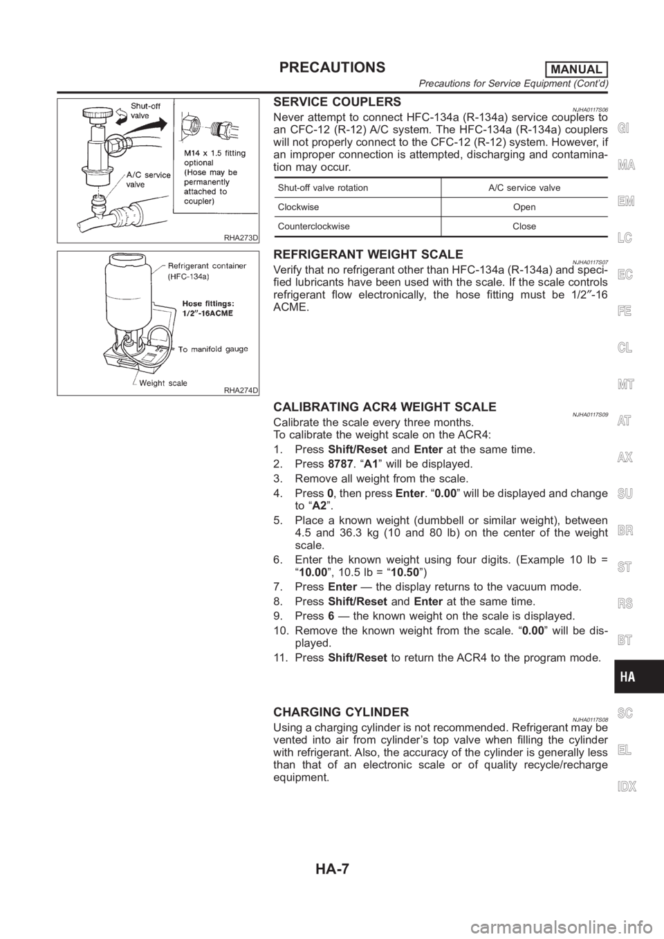
RHA273D
SERVICE COUPLERSNJHA0117S06Never attempt to connect HFC-134a (R-134a) service couplers to
an CFC-12 (R-12) A/C system. The HFC-134a (R-134a) couplers
will not properly connect to the CFC-12 (R-12) system. However, if
an improper connection is attempted, discharging and contamina-
tion may occur.
Shut-off valve rotation A/C service valve
Clockwise Open
Counterclockwise Close
RHA274D
REFRIGERANT WEIGHT SCALENJHA0117S07Verify that no refrigerant other than HFC-134a (R-134a) and speci-
fied lubricants have been used with the scale. If the scale controls
refrigerant flow electronically, the hose fitting must be 1/2″-16
ACME.
CALIBRATING ACR4 WEIGHT SCALENJHA0117S09Calibrate the scale every three months.
To calibrate the weight scale on the ACR4:
1. PressShift/ResetandEnterat the same time.
2. Press8787.“A1” will be displayed.
3. Remove all weight from the scale.
4. Press0, then pressEnter.“0.00” will be displayed and change
to “A2”.
5. Place a known weight (dumbbell or similar weight), between
4.5 and 36.3 kg (10 and 80 lb) on the center of the weight
scale.
6. Enter the known weight using four digits. (Example 10 lb =
“10.00”, 10.5 lb = “10.50”)
7. PressEnter— the display returns to the vacuum mode.
8. PressShift/ResetandEnterat the same time.
9. Press6— the known weight on the scale is displayed.
10. Remove the known weight from the scale. “0.00” will be dis-
played.
11. PressShift/Resetto return the ACR4 to the program mode.
CHARGING CYLINDERNJHA0117S08Using a charging cylinder is not recommended. Refrigerant may be
vented into air from cylinder’s top valve when filling the cylinder
with refrigerant. Also, the accuracy of the cylinder is generally less
than that of an electronic scale or of quality recycle/recharge
equipment.
GI
MA
EM
LC
EC
FE
CL
MT
AT
AX
SU
BR
ST
RS
BT
SC
EL
IDX
PRECAUTIONSMANUAL
Precautions for Service Equipment (Cont’d)
HA-7
Page 3073 of 3189

Trouble Diagnoses Introduction=NJRS0043CAUTION:
Do not use electrical test equipment on any circuit related to the SRS unless instructed to in this
Service Manual. SRS wiring harnesses can be identified by yellow harness connector.
Do not attempt to repair, splice or modify the SRS wiring harness. If the harness is damaged,
replace it with a new one.
Keep ground portion clean.
DIAGNOSIS FUNCTIONNJRS0043S01The SRS self-diagnosis results can be read by using “AIR BAG” warning lamp and/or CONSULT-II. The read-
ing of these results is accomplished using one of two modes — “User mode” and“Diagnosis mode”.
The User mode is exclusively prepared for the customer (driver). This modewarns the driver of a system
malfunction through the operation of the “AIR BAG” warning lamp.
The Diagnosis mode allows the technician to locate and inspect the malfunctioning part.
The mode applications for the “AIR BAG” warning lamp and CONSULT-II are as follows:
User mode Diagnosis mode Display type
“AIR BAG” warning lamp X X ON-OFF operation
CONSULT-II — X Monitoring
NOTE:
Seat belt pre-tensioner malfunction is indicated by “AIR BAG” warning lamp.
DIAGNOSIS MODE FOR CONSULT-IINJRS0043S02“SELF-DIAG [CURRENT]”
A current Self-diagnosis result (also indicated by the number of warning lamp flashes in the Diagnosis
mode) is displayed on the CONSULT-II screen in real time. This refers to a malfunctioning part requiring
repairs.
“SELF-DIAG [PAST]”
Diagnosis results previously stored in the memory are displayed on the CONSULT-II screen. The stored
results are not erased until memory erasing is executed.
“TROUBLE DIAG RECORD”
With TROUBLE DIAG RECORD, diagnosis results previously erased by a reset operation can be displayed
on the CONSULT-II screen.
“ECU DISCRIMINATED NO.”
The diagnosis sensor unit for each vehicle model is assigned with its own, individual classification num-
ber. This number will be displayed on the CONSULT-II screen, as shown below. When replacing the diag-
nosis sensor unit, refer to the part number for the compatibility. After installation, replacement with a cor-
rect unit can be checked by confirming this classification number on the CONSULT-II screen.
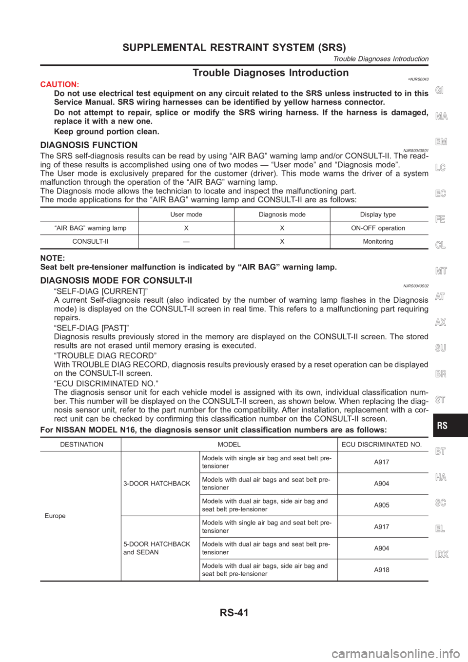
For NISSAN MODEL N16, the diagnosis sensor unit classification numbers are as follows:
DESTINATION MODEL ECU DISCRIMINATED NO.
Europe3-DOOR HATCHBACKModels with single air bag and seat belt pre-
tensionerA917
Models with dual air bags and seat belt pre-
tensionerA904
Models with dual air bags, side air bag and
seat belt pre-tensionerA905
5-DOOR HATCHBACK
and SEDANModels with single air bag and seat belt pre-
tensionerA917
Models with dual air bags and seat belt pre-
tensionerA904
Models with dual air bags, side air bag and
seat belt pre-tensionerA918
GI
MA
EM
LC
EC
FE
CL
MT
AT
AX
SU
BR
ST
BT
HA
SC
EL
IDX
SUPPLEMENTAL RESTRAINT SYSTEM (SRS)
Trouble Diagnoses Introduction
RS-41
Page 3089 of 3189
SRS697
6. Touch “SELF-DIAG [PAST]”.
SRS700
7. If diagnostic codes are displayed on “SELF-DIAG [PAST]”, go
to step 10.
SRS702
If no malfunction is detected on “SELF-DIAG [PAST]”, touch
“BACK” and go back to “SELECT DIAG MODE”.
SRS697
8. Touch “TROUBLE DIAG RECORD”.
NOTE:
With “TROUBLE DIAG RECORD”, diagnosis results previ-
ously erased by a reset operation can be displayed.
SRS704
9. Diagnostic code is displayed on “TROUBLE DIAG RECORD”.
GI
MA
EM
LC
EC
FE
CL
MT
AT
AX
SU
BR
ST
BT
HA
SC
EL
IDX
SUPPLEMENTAL RESTRAINT SYSTEM (SRS)
Trouble Diagnoses with CONSULT-II (Cont’d)
RS-57
Page 3098 of 3189

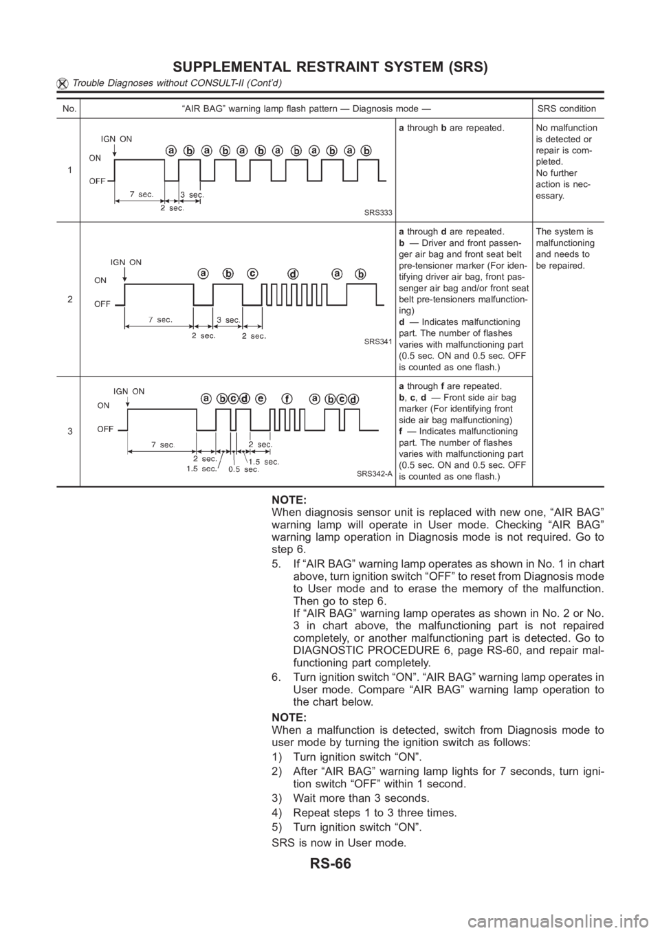
No. “AIR BAG” warning lamp flash pattern — Diagnosis mode — SRS condition
1
SRS333
athroughbare repeated. No malfunction
is detected or
repair is com-
pleted.
No further
action is nec-
essary.
2
SRS341
athroughdare repeated.
b— Driver and front passen-
ger air bag and front seat belt
pre-tensioner marker (For iden-
tifying driver air bag, front pas-
senger air bag and/or front seat
belt pre-tensioners malfunction-
ing)
d— Indicates malfunctioning
part. The number of flashes
varies with malfunctioning part
(0.5 sec. ON and 0.5 sec. OFF
is counted as one flash.)The system is
malfunctioning
and needs to
be repaired.
3
SRS342-A
athroughfare repeated.
b,c,d— Front side air bag
marker (For identifying front
side air bag malfunctioning)
f— Indicates malfunctioning
part. The number of flashes
varies with malfunctioning part
(0.5 sec. ON and 0.5 sec. OFF
is counted as one flash.)
NOTE:
When diagnosis sensor unit is replaced with new one, “AIR BAG”
warning lamp will operate in User mode. Checking “AIR BAG”
warning lamp operation in Diagnosis mode is not required. Go to
step 6.
5. If “AIR BAG” warning lamp operates as shown in No. 1 in chart
above, turn ignition switch “OFF” to reset from Diagnosis mode
to User mode and to erase the memory of the malfunction.
Then go to step 6.
If “AIR BAG” warning lamp operates as shown in No. 2 or No.
3 in chart above, the malfunctioning part is not repaired
completely, or another malfunctioning part is detected. Go to
DIAGNOSTIC PROCEDURE 6, page RS-60, and repair mal-
functioning part completely.
6. Turn ignition switch “ON”. “AIR BAG” warning lamp operates in
User mode. Compare “AIR BAG” warning lamp operation to
the chart below.
NOTE:
When a malfunction is detected, switch from Diagnosis mode to
user mode by turning the ignition switch as follows:
1) Turn ignition switch “ON”.
2) After “AIR BAG” warning lamp lights for 7 seconds, turn igni-
tion switch “OFF” within 1 second.
3) Wait more than 3 seconds.
4) Repeat steps 1 to 3 three times.
5) Turn ignition switch “ON”.
SRS is now in User mode.
SUPPLEMENTAL RESTRAINT SYSTEM (SRS)
Trouble Diagnoses without CONSULT-II (Cont’d)
RS-66