Page 1255 of 3189

3 CHECK EGR VOLUME CONTROL VALVE POWER SUPPLY CIRCUIT-II
1. Turn ignition switch “OFF”.
2. Disconnect ECM relay. (For ECM relay location, refer to “Engine ControlComponent Parts Location”.)
3. Check harness continuity between ECM relay terminal 5 and EGR volume control valve terminals 2 and 5. Refer to
Wiring Diagram.
Continuity should exist.
OK or NG
OK GO TO 5.
NG GO TO 4.
4 DETECT MALFUNCTIONING PART
Check the following.
Harness connectors E174, M159 (LHD models)
Harness connectors E251, M182 (RHD models)
Harness connectors M63, F102
Harness for open or short between ECM relay and EGR volume control valve
Repair open circuit or short to power in harness or connectors.
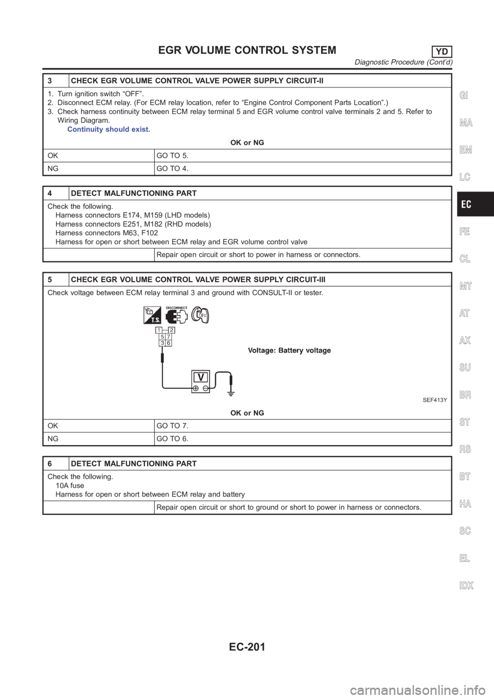
5 CHECK EGR VOLUME CONTROL VALVE POWER SUPPLY CIRCUIT-III
Check voltage between ECM relay terminal 3 and ground with CONSULT-II or tester.
SEF413Y
OK or NG
OK GO TO 7.
NG GO TO 6.
6 DETECT MALFUNCTIONING PART
Check the following.
10A fuse
Harness for open or short between ECM relay and battery
Repair open circuit or short to ground or short to power in harness or connectors.
GI
MA
EM
LC
FE
CL
MT
AT
AX
SU
BR
ST
RS
BT
HA
SC
EL
IDX
EGR VOLUME CONTROL SYSTEMYD
Diagnostic Procedure (Cont’d)
EC-201
Page 1256 of 3189
7 CHECK ECM RELAY
1. Apply 12V direct current between ECM relay terminals 1 and 2.
2. Check continuity between ECM relay terminals 3 and 5, 6 and 7.
SEF296X
OK or NG
OK GO TO 8.
NG Replace ECM relay.
8 CHECK EGR VOLUME CONTROL VALVE OUTPUT SIGNAL CIRCUIT FOR OPEN AND SHORT
1. Turn ignition switch “OFF”.
2. Disconnect ECM harness connector.
3. Check harness continuity between ECM terminals and EGR volume control valve terminals as follows.
Refer to Wiring Diagram.
MTBL0463
Continuity should exist.
4. Also check harness for short to ground and short to power.
OK or NG
OK GO TO 9.
NG Repair open circuit or short to ground or short to power in harness or connectors.
EGR VOLUME CONTROL SYSTEMYD
Diagnostic Procedure (Cont’d)
EC-202
Page 1259 of 3189
Wiring DiagramNJEC0769
YEC330A
GI
MA
EM
LC
FE
CL
MT
AT
AX
SU
BR
ST
RS
BT
HA
SC
EL
IDX
START SIGNALYD
Wiring Diagram
EC-205
Page 1260 of 3189

Diagnostic ProcedureNJEC0770
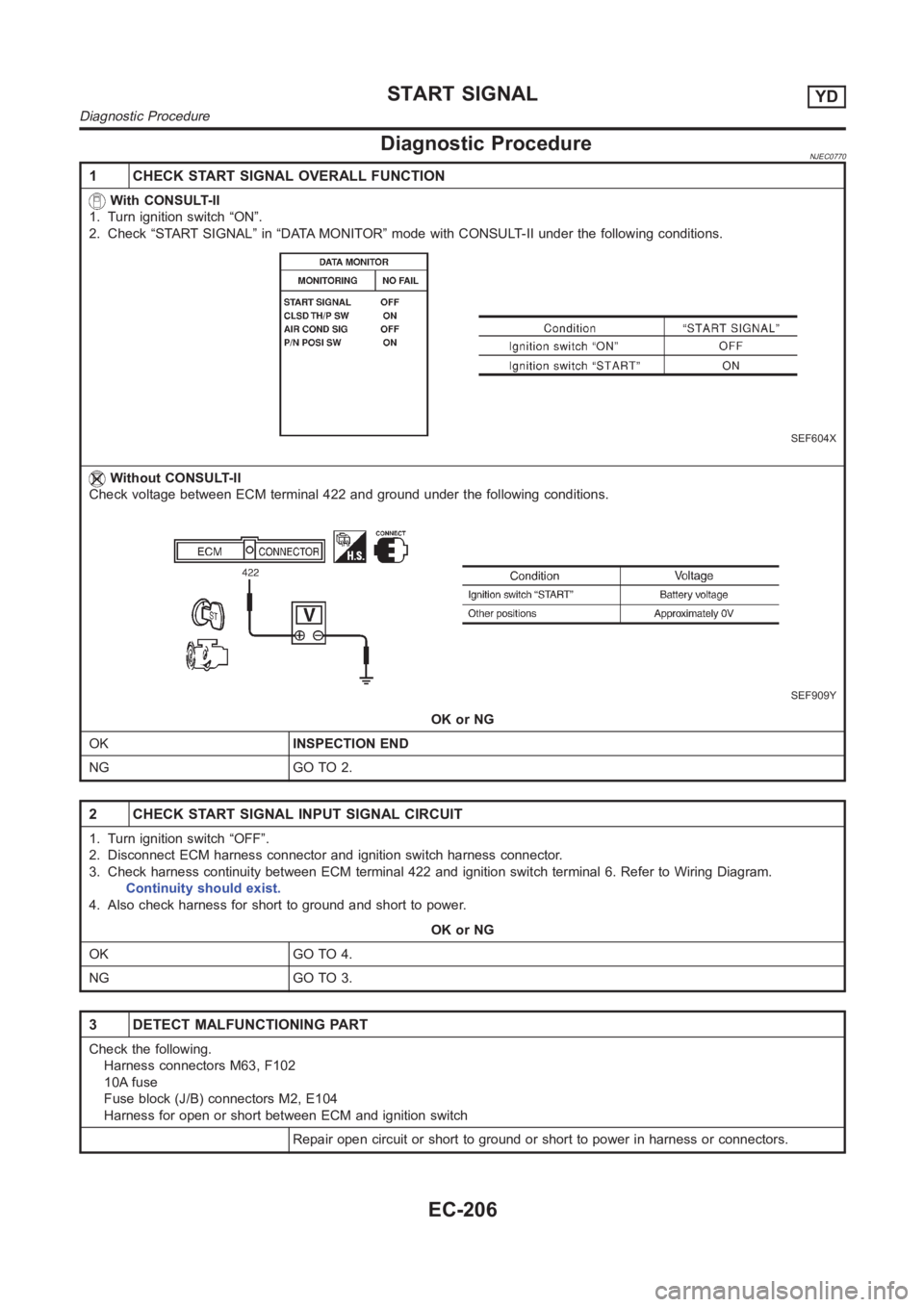
1 CHECK START SIGNAL OVERALL FUNCTION
With CONSULT-II
1. Turn ignition switch “ON”.
2. Check “START SIGNAL” in “DATA MONITOR” mode with CONSULT-II under the following conditions.
SEF604X
Without CONSULT-II
Check voltage between ECM terminal 422 and ground under the following conditions.
SEF909Y
OK or NG
OKINSPECTION END
NG GO TO 2.
2 CHECK START SIGNAL INPUT SIGNAL CIRCUIT
1. Turn ignition switch “OFF”.
2. Disconnect ECM harness connector and ignition switch harness connector.
3. Check harness continuity between ECM terminal 422 and ignition switch terminal 6. Refer to Wiring Diagram.
Continuity should exist.
4. Also check harness for short to ground and short to power.
OK or NG
OK GO TO 4.
NG GO TO 3.
3 DETECT MALFUNCTIONING PART
Check the following.
Harness connectors M63, F102
10A fuse
Fuse block (J/B) connectors M2, E104
Harness for open or short between ECM and ignition switch
Repair open circuit or short to ground or short to power in harness or connectors.
START SIGNALYD
Diagnostic Procedure
EC-206
Page 1263 of 3189
Wiring DiagramNJEC0784
YEC022A
GI
MA
EM
LC
FE
CL
MT
AT
AX
SU
BR
ST
RS
BT
HA
SC
EL
IDX
PARK/NEUTRAL POSITION (PNP) SWITCH (WHERE FITTED)YD
Wiring Diagram
EC-209
Page 1265 of 3189

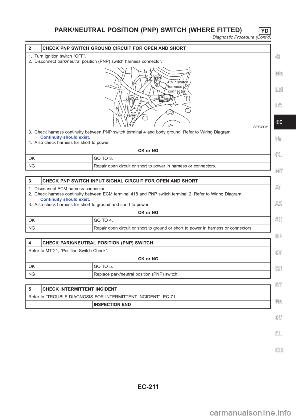
2 CHECK PNP SWITCH GROUND CIRCUIT FOR OPEN AND SHORT
1. Turn ignition switch “OFF”.
2. Disconnect park/neutral position (PNP) switch harness connector.
SEF393Y
3. Check harness continuity between PNP switch terminal 4 and body ground.Refer to Wiring Diagram.
Continuity should exist.
4. Also check harness for short to power.
OK or NG
OK GO TO 3.
NG Repair open circuit or short to power in harness or connectors.
3 CHECK PNP SWITCH INPUT SIGNAL CIRCUIT FOR OPEN AND SHORT
1. Disconnect ECM harness connector.
2. Check harness continuity between ECM terminal 418 and PNP switch terminal 2. Refer to Wiring Diagram.
Continuity should exist.
3. Also check harness for short to ground and short to power.
OK or NG
OK GO TO 4.
NG Repair open circuit or short to ground or short to power in harness or connectors.
4 CHECK PARK/NEUTRAL POSITION (PNP) SWITCH
Refer to MT-21, “Position Switch Check”.
OK or NG
OK GO TO 5.
NG Replace park/neutral position (PNP) switch.
5 CHECK INTERMITTENT INCIDENT
Refer to “TROUBLE DIAGNOSIS FOR INTERMITTENT INCIDENT”, EC-71.
INSPECTION END
GI
MA
EM
LC
FE
CL
MT
AT
AX
SU
BR
ST
RS
BT
HA
SC
EL
IDX
PARK/NEUTRAL POSITION (PNP) SWITCH (WHERE FITTED)YD
Diagnostic Procedure (Cont’d)
EC-211
Page 1266 of 3189
Wiring DiagramNJEC0786
YEC331A
AIR CONDITIONER CONTROLYD
Wiring Diagram
EC-212
Page 1267 of 3189
Wiring DiagramNJEC0787
YEC332A
GI
MA
EM
LC
FE
CL
MT
AT
AX
SU
BR
ST
RS
BT
HA
SC
EL
IDX
MI & DATA LINK CONNECTORSYD
Wiring Diagram
EC-213