Page 1151 of 3189

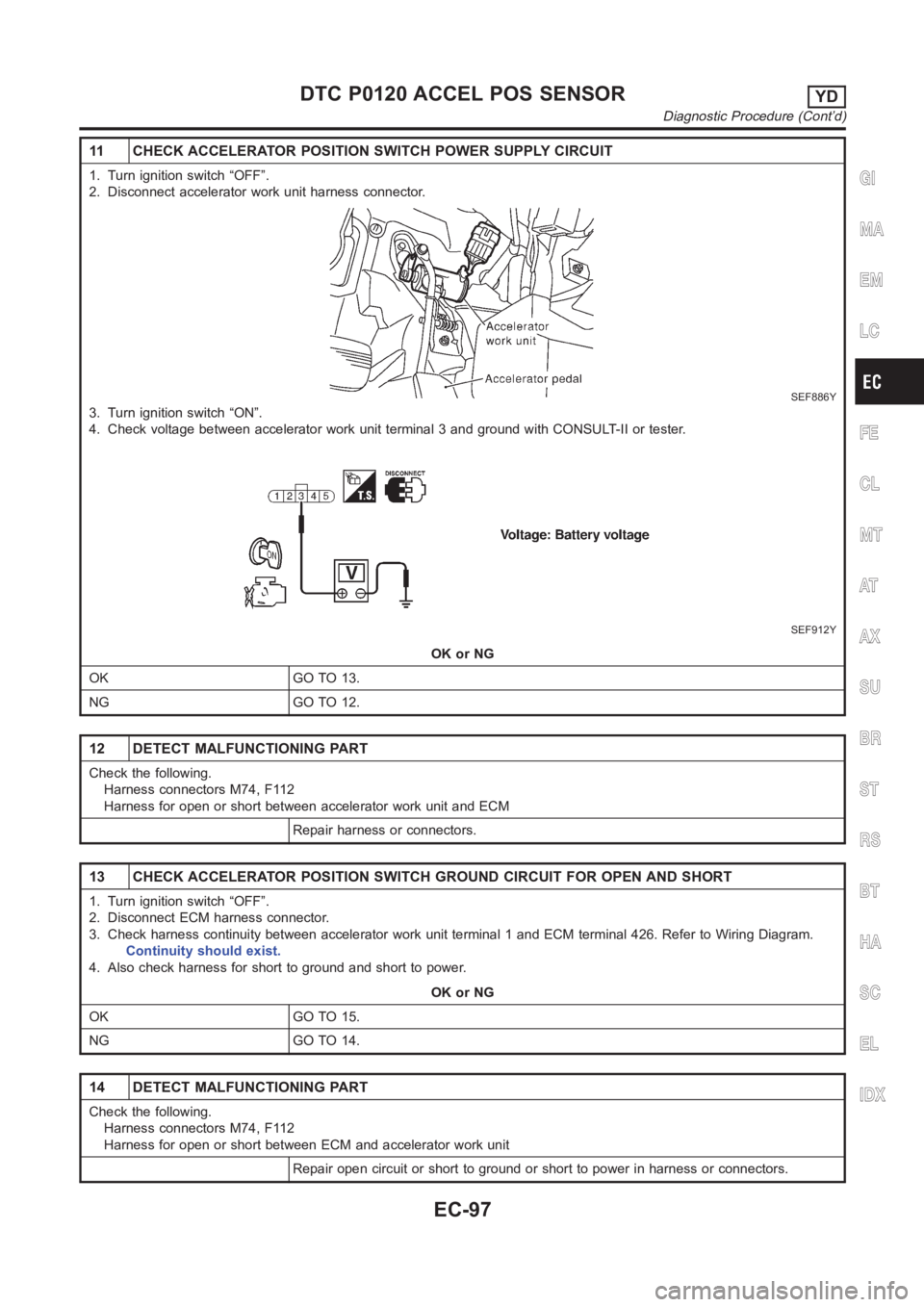
11 CHECK ACCELERATOR POSITION SWITCH POWER SUPPLY CIRCUIT
1. Turn ignition switch “OFF”.
2. Disconnect accelerator work unit harness connector.
SEF886Y
3. Turn ignition switch “ON”.
4. Check voltage between accelerator work unit terminal 3 and ground with CONSULT-II or tester.
SEF912Y
OK or NG
OK GO TO 13.
NG GO TO 12.
12 DETECT MALFUNCTIONING PART
Check the following.
Harness connectors M74, F112
Harness for open or short between accelerator work unit and ECM
Repair harness or connectors.
13 CHECK ACCELERATOR POSITION SWITCH GROUND CIRCUIT FOR OPEN AND SHORT
1. Turn ignition switch “OFF”.
2. Disconnect ECM harness connector.
3. Check harness continuity between accelerator work unit terminal 1 and ECM terminal 426. Refer to Wiring Diagram.
Continuity should exist.
4. Also check harness for short to ground and short to power.
OK or NG
OK GO TO 15.
NG GO TO 14.
14 DETECT MALFUNCTIONING PART
Check the following.
Harness connectors M74, F112
Harness for open or short between ECM and accelerator work unit
Repair open circuit or short to ground or short to power in harness or connectors.
GI
MA
EM
LC
FE
CL
MT
AT
AX
SU
BR
ST
RS
BT
HA
SC
EL
IDX
DTC P0120 ACCEL POS SENSORYD
Diagnostic Procedure (Cont’d)
EC-97
Page 1155 of 3189
Wiring DiagramNJEC0691
YEC013A
GI
MA
EM
LC
FE
CL
MT
AT
AX
SU
BR
ST
RS
BT
HA
SC
EL
IDX
DTC P0335 CRANK POS SEN (TDC)YD
Wiring Diagram
EC-101
Page 1156 of 3189

Diagnostic ProcedureNJEC0692
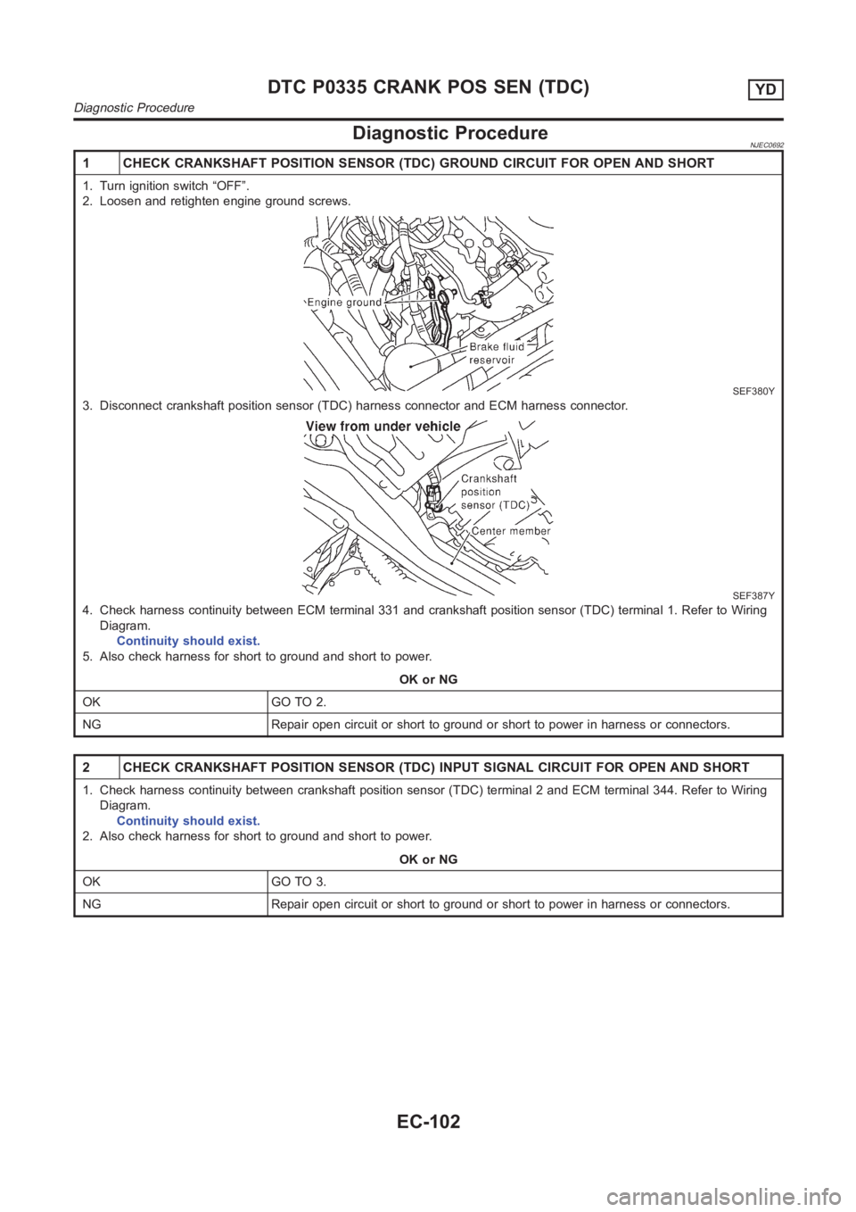
1 CHECK CRANKSHAFT POSITION SENSOR (TDC) GROUND CIRCUIT FOR OPEN AND SHORT
1. Turn ignition switch “OFF”.
2. Loosen and retighten engine ground screws.
SEF380Y
3. Disconnect crankshaft position sensor (TDC) harness connector and ECMharness connector.
SEF387Y
4. Check harness continuity between ECM terminal 331 and crankshaft position sensor (TDC) terminal 1. Refer to Wiring
Diagram.
Continuity should exist.
5. Also check harness for short to ground and short to power.
OK or NG
OK GO TO 2.
NG Repair open circuit or short to ground or short to power in harness or connectors.
2 CHECK CRANKSHAFT POSITION SENSOR (TDC) INPUT SIGNAL CIRCUIT FOR OPEN ANDSHORT
1. Check harness continuity between crankshaft position sensor (TDC) terminal 2 and ECM terminal 344. Refer to Wiring
Diagram.
Continuity should exist.
2. Also check harness for short to ground and short to power.
OK or NG
OK GO TO 3.
NG Repair open circuit or short to ground or short to power in harness or connectors.
DTC P0335 CRANK POS SEN (TDC)YD
Diagnostic Procedure
EC-102
Page 1161 of 3189
Wiring DiagramNJEC0658
YEC323A
GI
MA
EM
LC
FE
CL
MT
AT
AX
SU
BR
ST
RS
BT
HA
SC
EL
IDX
DTC P0500 VEHICLE SPEED SENYD
Wiring Diagram
EC-107
Page 1162 of 3189

Diagnostic ProcedureNJEC0659
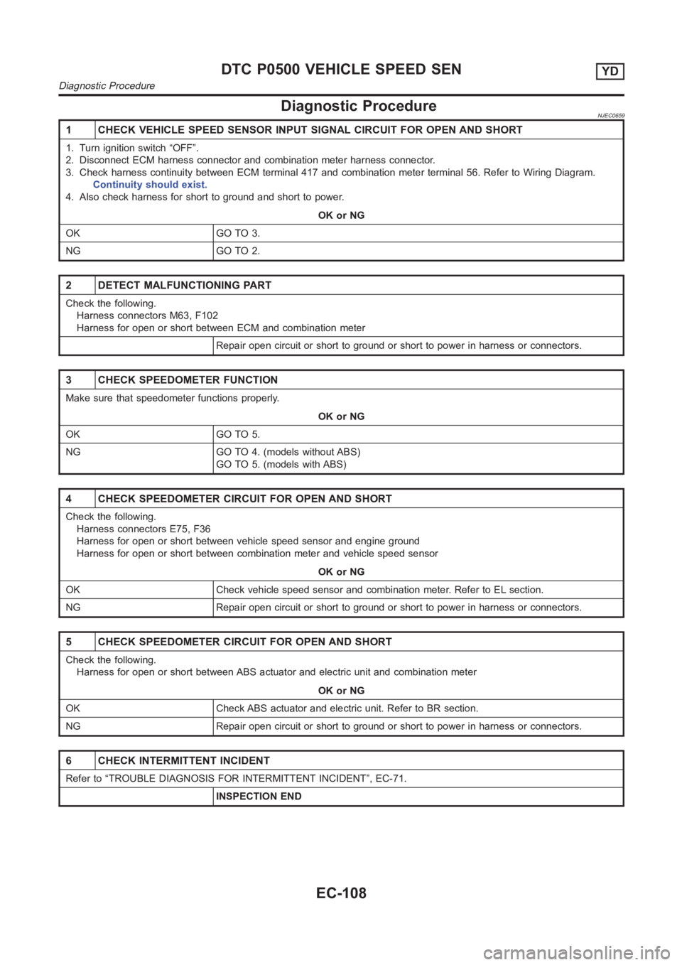
1 CHECK VEHICLE SPEED SENSOR INPUT SIGNAL CIRCUIT FOR OPEN AND SHORT
1. Turn ignition switch “OFF”.
2. Disconnect ECM harness connector and combination meter harness connector.
3. Check harness continuity between ECM terminal 417 and combination meter terminal 56. Refer to Wiring Diagram.
Continuity should exist.
4. Also check harness for short to ground and short to power.
OK or NG
OK GO TO 3.
NG GO TO 2.
2 DETECT MALFUNCTIONING PART
Check the following.
Harness connectors M63, F102
Harness for open or short between ECM and combination meter
Repair open circuit or short to ground or short to power in harness or connectors.
3 CHECK SPEEDOMETER FUNCTION
Make sure that speedometer functions properly.
OK or NG
OK GO TO 5.
NG GO TO 4. (models without ABS)
GO TO 5. (models with ABS)
4 CHECK SPEEDOMETER CIRCUIT FOR OPEN AND SHORT
Check the following.
Harness connectors E75, F36
Harness for open or short between vehicle speed sensor and engine ground
Harness for open or short between combination meter and vehicle speed sensor
OK or NG
OK Check vehicle speed sensor and combination meter. Refer to EL section.
NG Repair open circuit or short to ground or short to power in harness or connectors.
5 CHECK SPEEDOMETER CIRCUIT FOR OPEN AND SHORT
Check the following.
Harness for open or short between ABS actuator and electric unit and combination meter
OK or NG
OK Check ABS actuator and electric unit. Refer to BR section.
NG Repair open circuit or short to ground or short to power in harness or connectors.
6 CHECK INTERMITTENT INCIDENT
Refer to “TROUBLE DIAGNOSIS FOR INTERMITTENT INCIDENT”, EC-71.
INSPECTION END
DTC P0500 VEHICLE SPEED SENYD
Diagnostic Procedure
EC-108
Page 1165 of 3189
Wiring DiagramNJEC0742
YEC324A
GI
MA
EM
LC
FE
CL
MT
AT
AX
SU
BR
ST
RS
BT
HA
SC
EL
IDX
DTC P0571 BRAKE SWYD
Wiring Diagram
EC-111
Page 1167 of 3189
4 CHECK STOP LAMP SWITCH INPUT SIGNAL CIRCUIT FOR OPEN AND SHORT
1. Turn ignition switch “OFF”.
2. Disconnect ECM harness connector.
3. Disconnect stop lamp switch harness connector.
SEF893Y
4. Check harness continuity between ECM terminal 405 and stop lamp switch terminal 2. Refer to Wiring Diagram.
Continuity should exist.
5. Also check harness for short to ground and short to power.
OK or NG
OK GO TO 6.
NG GO TO 5.
5 DETECT MALFUNCTIONING PART
Check the following.
Harness connectors M74, F112
Harness for open or short between ECM and stop lamp switch
Repair open circuit or short to ground or short to power in harness or connectors.
6 CHECK STOP LAMP SWITCH
Check continuity between stop lamp switch terminals 1 and 2 under the following conditions.
SEF904Y
OK or NG
OK GO TO 7.
NG Replace stop lamp switch.
GI
MA
EM
LC
FE
CL
MT
AT
AX
SU
BR
ST
RS
BT
HA
SC
EL
IDX
DTC P0571 BRAKE SWYD
Diagnostic Procedure (Cont’d)
EC-113
Page 1175 of 3189
Wiring DiagramNJEC0677
YEC325A
GI
MA
EM
LC
FE
CL
MT
AT
AX
SU
BR
ST
RS
BT
HA
SC
EL
IDX
DTC P1180 P9·FUEL TEMP SENYD
Wiring Diagram
EC-121