Page 1228 of 3189
4 CHECK COMMUNICATION LINE FOR OPEN AND SHORT
1. Check continuity between the following terminals. Refer to Wiring Diagram.
MTBL0462
Continuity should exist.
2. Also check harness for short to ground and short to power.
OK or NG
OK GO TO 5.
NG Repair open circuit or short to ground or short to power in harness or connectors.
5 CHECK INTERMITTENT INCIDENT
Refer to “TROUBLE DIAGNOSIS FOR INTERMITTENT INCIDENT”, EC-71.
OK or NG
OK Replace electronic control fuel injection pump.
NG Repair open circuit or short to ground or short to power in harness or connectors.
DTC P1600 P3·PUMP COMM LINEYD
Diagnostic Procedure (Cont’d)
EC-174
Page 1232 of 3189
Wiring DiagramNJEC0747
YEC327A
DTC P1620 ECM RLYYD
Wiring Diagram
EC-178
Page 1233 of 3189

Diagnostic ProcedureNJEC0748
1 CHECK ECM POWER SUPPLY CIRCUIT
1. Turn ignition switch “OFF”.
2. Disconnect ECM relay. (For ECM relay location, refer to “Engine ControlComponent Parts Location”.)
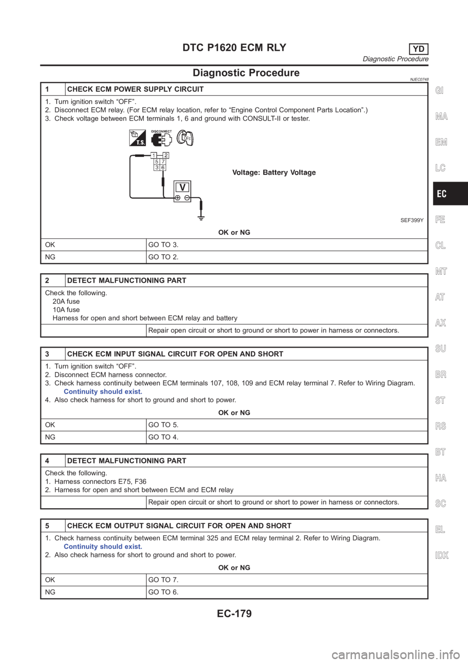
3. Check voltage between ECM terminals 1, 6 and ground with CONSULT-II or tester.
SEF399Y
OK or NG
OK GO TO 3.
NG GO TO 2.
2 DETECT MALFUNCTIONING PART
Check the following.
20A fuse
10A fuse
Harness for open and short between ECM relay and battery
Repair open circuit or short to ground or short to power in harness or connectors.
3 CHECK ECM INPUT SIGNAL CIRCUIT FOR OPEN AND SHORT
1. Turn ignition switch “OFF”.
2. Disconnect ECM harness connector.
3. Check harness continuity between ECM terminals 107, 108, 109 and ECM relay terminal 7. Refer to Wiring Diagram.
Continuity should exist.
4. Also check harness for short to ground and short to power.
OK or NG
OK GO TO 5.
NG GO TO 4.
4 DETECT MALFUNCTIONING PART
Check the following.
1. Harness connectors E75, F36
2. Harness for open and short between ECM and ECM relay
Repair open circuit or short to ground or short to power in harness or connectors.
5 CHECK ECM OUTPUT SIGNAL CIRCUIT FOR OPEN AND SHORT
1. Check harness continuity between ECM terminal 325 and ECM relay terminal 2. Refer to Wiring Diagram.
Continuity should exist.
2. Also check harness for short to ground and short to power.
OK or NG
OK GO TO 7.
NG GO TO 6.
GI
MA
EM
LC
FE
CL
MT
AT
AX
SU
BR
ST
RS
BT
HA
SC
EL
IDX
DTC P1620 ECM RLYYD
Diagnostic Procedure
EC-179
Page 1244 of 3189
Wiring DiagramNJEC0762
YEC328A
GLOW CONTROL SYSTEMYD
Wiring Diagram
EC-190
Page 1247 of 3189

6 CHECK GLOW INDICATOR LAMP POWER SUPPLY CIRCUIT
1. Turn ignition switch “OFF”.
2. Disconnect combination meter harness connector M171.
3. Turn ignition switch “ON”.
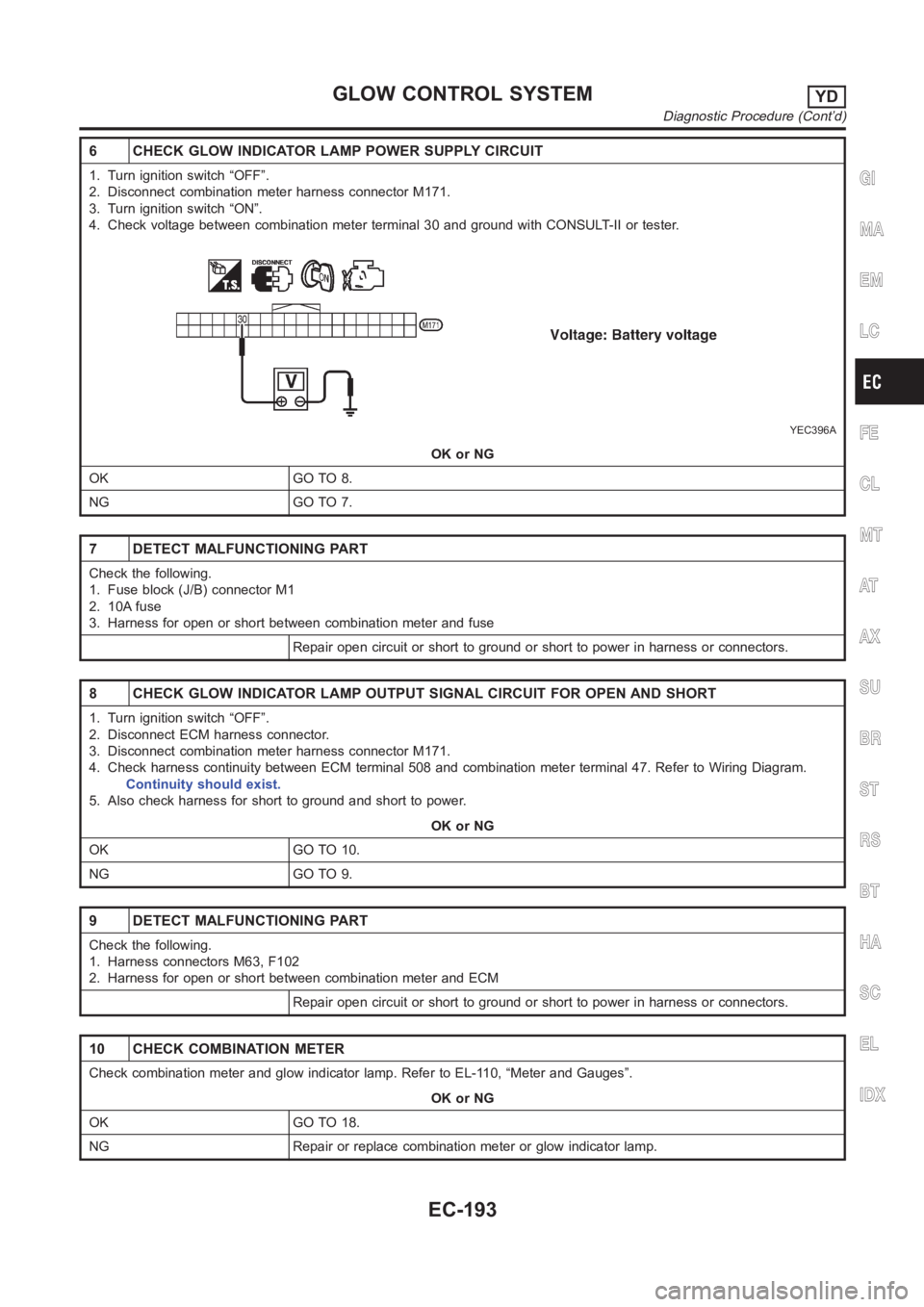
4. Check voltage between combination meter terminal 30 and ground with CONSULT-II or tester.
YEC396A
OK or NG
OK GO TO 8.
NG GO TO 7.
7 DETECT MALFUNCTIONING PART
Check the following.
1. Fuse block (J/B) connector M1
2. 10A fuse
3. Harness for open or short between combination meter and fuse
Repair open circuit or short to ground or short to power in harness or connectors.
8 CHECK GLOW INDICATOR LAMP OUTPUT SIGNAL CIRCUIT FOR OPEN AND SHORT
1. Turn ignition switch “OFF”.
2. Disconnect ECM harness connector.
3. Disconnect combination meter harness connector M171.
4. Check harness continuity between ECM terminal 508 and combination meter terminal 47. Refer to Wiring Diagram.
Continuity should exist.
5. Also check harness for short to ground and short to power.
OK or NG
OK GO TO 10.
NG GO TO 9.
9 DETECT MALFUNCTIONING PART
Check the following.
1. Harness connectors M63, F102
2. Harness for open or short between combination meter and ECM
Repair open circuit or short to ground or short to power in harness or connectors.
10 CHECK COMBINATION METER
Check combination meter and glow indicator lamp. Refer to EL-110, “Meter and Gauges”.
OK or NG
OK GO TO 18.
NG Repair or replace combination meter or glow indicator lamp.
GI
MA
EM
LC
FE
CL
MT
AT
AX
SU
BR
ST
RS
BT
HA
SC
EL
IDX
GLOW CONTROL SYSTEMYD
Diagnostic Procedure (Cont’d)
EC-193
Page 1248 of 3189

11 CHECK GLOW RELAY POWER SUPPLY CIRCUIT
1. Turn ignition switch “OFF”.
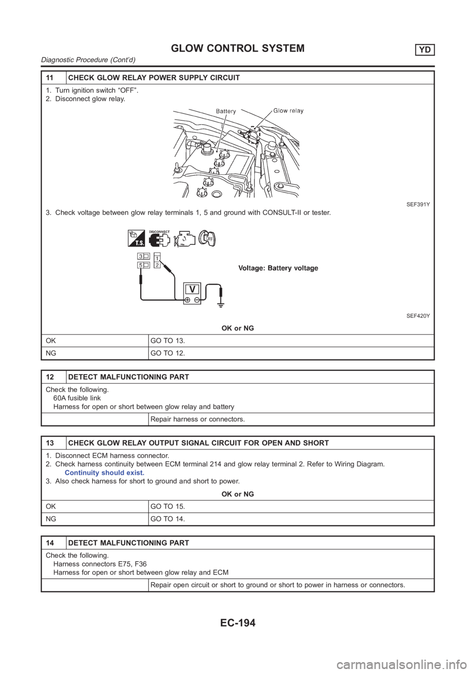
2. Disconnect glow relay.
SEF391Y
3. Check voltage between glow relay terminals 1, 5 and ground with CONSULT-II or tester.
SEF420Y
OK or NG
OK GO TO 13.
NG GO TO 12.
12 DETECT MALFUNCTIONING PART
Check the following.
60A fusible link
Harness for open or short between glow relay and battery
Repair harness or connectors.
13 CHECK GLOW RELAY OUTPUT SIGNAL CIRCUIT FOR OPEN AND SHORT
1. Disconnect ECM harness connector.
2. Check harness continuity between ECM terminal 214 and glow relay terminal 2. Refer to Wiring Diagram.
Continuity should exist.
3. Also check harness for short to ground and short to power.
OK or NG
OK GO TO 15.
NG GO TO 14.
14 DETECT MALFUNCTIONING PART
Check the following.
Harness connectors E75, F36
Harness for open or short between glow relay and ECM
Repair open circuit or short to ground or short to power in harness or connectors.
GLOW CONTROL SYSTEMYD
Diagnostic Procedure (Cont’d)
EC-194
Page 1249 of 3189

15 CHECK HARNESS CONTINUITY BETWEEN GLOW RELAY AND GLOW PLUG FOR OPEN AND SHORT
1. Disconnect glow plug harness connector.
2. Check harness continuity between glow relay terminal 3 and glow plug harness connector. Refer to Wiring Diagram.
Continuity should exist.
3. Also check harness for short to ground and short to power.
OK or NG
OK GO TO 16.
NG Repair open circuit or short to ground or short to power in harness or connectors.
16 CHECK GLOW RELAY
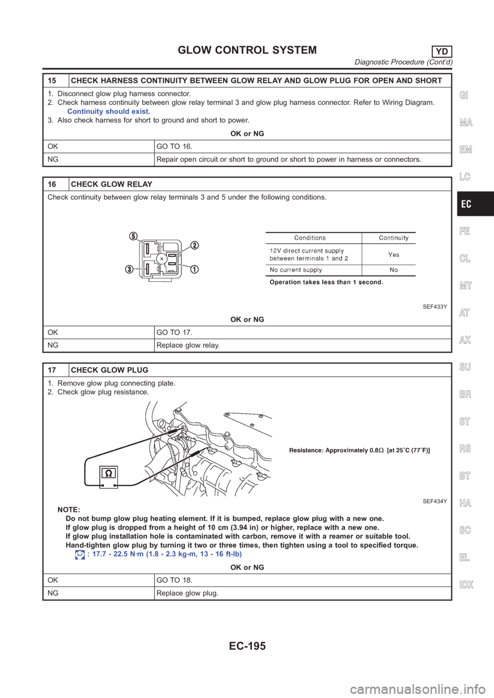
Check continuity between glow relay terminals 3 and 5 under the following conditions.
SEF433Y
OK or NG
OK GO TO 17.
NG Replace glow relay.
17 CHECK GLOW PLUG
1. Remove glow plug connecting plate.
2. Check glow plug resistance.
SEF434Y
NOTE:
Do not bump glow plug heating element. If it is bumped, replace glow plug withanewone.
If glow plug is dropped from a height of 10 cm (3.94 in) or higher, replace with a new one.
If glow plug installation hole is contaminated with carbon, remove it witha reamer or suitable tool.
Hand-tighten glow plug by turning it two or three times, then tighten usinga tool to specified torque.
: 17.7 - 22.5 N·m (1.8 - 2.3 kg-m, 13 - 16 ft-lb)
OK or NG
OK GO TO 18.
NG Replace glow plug.
GI
MA
EM
LC
FE
CL
MT
AT
AX
SU
BR
ST
RS
BT
HA
SC
EL
IDX
GLOW CONTROL SYSTEMYD
Diagnostic Procedure (Cont’d)
EC-195
Page 1253 of 3189
Wiring Diagram=NJEC0767
YEC329A
GI
MA
EM
LC
FE
CL
MT
AT
AX
SU
BR
ST
RS
BT
HA
SC
EL
IDX
EGR VOLUME CONTROL SYSTEMYD
Wiring Diagram
EC-199