Page 2123 of 3189

REFRIGERANT LINES
ATC-143
C
D
E
F
G
H
I
K
L
MA
B
AT C
Dual-pressure SwitchEJS0020Q
REMOVAL AND INSTALLATION
1. Use refrigerant collecting equipment (for HFC-134a) to discharge refrigerant.
2. Remove the liquid tank.
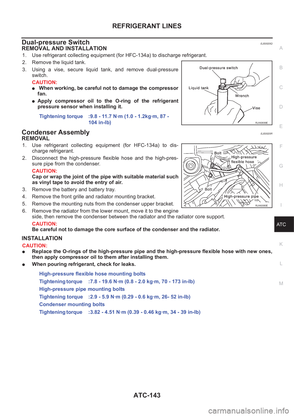
3. Using a vise, secure liquid tank, and remove dual-pressure
switch.
CAUTION:
● When working, be careful not to damage the compressor
fan.
●Apply compressor oil to the O-ring of the refrigerant
pressure sensor when installing it.
Condenser AssemblyEJS0020R
REMOVAL
1. Use refrigerant collecting equipment (for HFC-134a) to dis-
charge refrigerant.
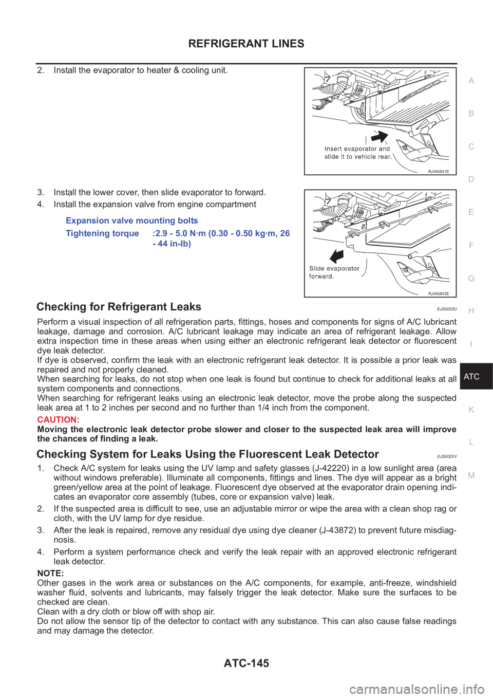
2. Disconnect the high-pressure flexible hose and the high-pres-
sure pipe from the condenser.
CAUTION:
Cap or wrap the joint of the pipe with suitable material such
as vinyl tape to avoid the entry of air.
3. Remove the battery and battery tray.
4. Remove the front grille and radiator mounting bracket.
5. Remove the mounting nuts from the condenser upper bracket.
6. Remove the radiator from the lower mount, move it to the engine
side, then remove the condenser between the radiator and the radiator core support.
CAUTION:
Be careful not to damage the core surface of the condenser and the radiator.
INSTALLATION
CAUTION:
●Replace the O-rings of the high-pressure pipe and the high-pressure flexible hose with new ones,
then apply compressor oil to them after installing them.
●When pouring refrigerant, check for leaks.Tightening torque :9.8 - 11.7 N·m (1.0 - 1.2kg·m, 87 -
104 in-lb)
RJIA0699E
RJIA0080E
High-pressure flexible hose mounting bolts
Tightening torque :7.8 - 19.6 N·m (0.8 - 2.0 kg·m, 70 - 173 in-lb)
High-pressure pipe mounting bolts
Tightening torque :2.9 - 5.9 N·m (0.29 - 0.6 kg·m, 26- 52 in-lb)
Condenser mounting bolts
Tightening torque :3.82 - 4.51 N·m (0.39 - 0.46 kg·m, 34 - 39 in-lb)
Page 2125 of 3189

REFRIGERANT LINES
ATC-145
C
D
E
F
G
H
I
K
L
MA
B
AT C
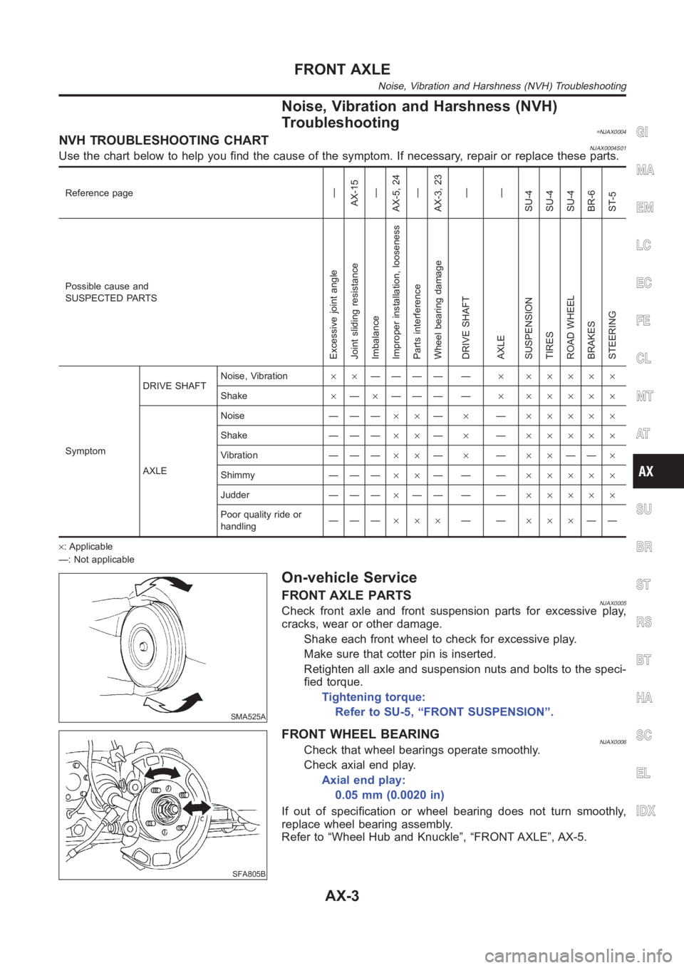
2. Install the evaporator to heater & cooling unit.
3. Install the lower cover, then slide evaporator to forward.
4. Install the expansion valve from engine compartment
Checking for Refrigerant LeaksEJS0020U
Perform a visual inspection of all refrigeration parts, fittings, hoses and components for signs of A/C lubricant
leakage, damage and corrosion. A/C lubricant leakage may indicate an area of refrigerant leakage. Allow
extra inspection time in these areas when using either an electronic refrigerant leak detector or fluorescent
dye leak detector.
If dye is observed, confirm the leak with an electronic refrigerant leak detector. It is possible a prior leak was
repaired and not properly cleaned.
When searching for leaks, do not stop when one leak is found but continue to check for additional leaks at all
system components and connections.
When searching for refrigerant leaks using an electronic leak detector, move the probe along the suspected
leak area at 1 to 2 inches per second and no further than 1/4 inch from the component.
CAUTION:
Moving the electronic leak detector probe slower and closer to the suspected leak area will improve
the chances of finding a leak.
Checking System for Leaks Using the Fluorescent Leak DetectorEJS0020V
1. Check A/C system for leaks using the UV lamp and safety glasses (J-42220) in a low sunlight area (area
without windows preferable). Illuminate all components, fittings and lines. The dye will appear as a bright
green/yellow area at the point of leakage. Fluorescent dye observed at the evaporator drain opening indi-
cates an evaporator core assembly (tubes, core or expansion valve) leak.
2. If the suspected area is difficult to see, use an adjustable mirror or wipe the area with a clean shop rag or
cloth, with the UV lamp for dye residue.
3. After the leak is repaired, remove any residual dye using dye cleaner (J-43872) to prevent future misdiag-
nosis.
4. Perform a system performance check and verify the leak repair with an approved electronic refrigerant
leak detector.
NOTE:
Other gases in the work area or substances on the A/C components, for example, anti-freeze, windshield
washer fluid, solvents and lubricants, may falsely trigger the leak detector. Make sure the surfaces to be
checked are clean.
Clean with a dry cloth or blow off with shop air.
Do not allow the sensor tip of the detector to contact with any substance. This can also cause false readings
and may damage the detector.
RJIA0841E
Expansion valve mounting bolts
Tightening torque :2.9 - 5.0 N·m (0.30 - 0.50 kg·m, 26
- 44 in-lb)
RJIA0842E
Page 2132 of 3189
SBR686C
Precautions
PRECAUTIONSNJAX0001When installing rubber parts, final tightening must be car-
ried out under unladen condition* with tires on ground.
*: Fuel, radiator coolant and engine oil full. Spare tire, jack,
hand tools and mats in designated positions.
After installing removed suspension parts, check wheel
alignment and adjust if necessary.
Use flare nut wrench when removing or installing brake
tubes.
Always torque brake lines when installing.
Preparation
SPECIAL SERVICE TOOLSNJAX0002
Tool number
Tool nameDescription
HT72520000
Ball joint remover
NT146
Removing tie-rod outer end and lower ball joint
KV38106800
Differential side oil seal
protector
NT147
Installing drive shaft
KV38106800
COMMERCIAL SERVICE TOOLSNJAX0003
Tool name Description
1 Flare nut crowfoot
2 Torque wrench
NT360
Removing and installing each brake piping
a: 10 mm (0.39 in)
FRONT AXLE
Precautions
AX-2
Page 2133 of 3189

Noise, Vibration and Harshness (NVH)
Troubleshooting
=NJAX0004NVH TROUBLESHOOTING CHARTNJAX0004S01Use the chart below to help you find the cause of the symptom. If necessary, repair or replace these parts.
Reference page—
AX-15
—
AX-5, 24
—
AX-3, 23
—
—
SU-4
SU-4
SU-4
BR-6
ST-5
Possible cause and
SUSPECTED PARTS
Excessive joint angle
Joint sliding resistance
Imbalance
Improper installation, looseness
Parts interference
Wheel bearing damage
DRIVE SHAFT
AXLE
SUSPENSION
TIRES
ROAD WHEEL
BRAKES
STEERING
SymptomDRIVE SHAFTNoise, Vibration××———— —× ×××××
Shake×—×——— —× ×××××
AXLENoise — — —××—×—×××××
Shake — — —××—×—×××××
Vibration — — —××—×—××——×
Shimmy — — —××—— —×××××
Judder — — —×—— — —×××××
Poor quality ride or
handling———×××——×××——
×: Applicable
—: Not applicable
SMA525A
On-vehicle Service
FRONT AXLE PARTSNJAX0005Check front axle and front suspension parts for excessive play,
cracks, wear or other damage.
Shake each front wheel to check for excessive play.
Make sure that cotter pin is inserted.
Retighten all axle and suspension nuts and bolts to the speci-
fied torque.
Tightening torque:
Refer to SU-5, “FRONT SUSPENSION”.
SFA805B
FRONT WHEEL BEARINGNJAX0006Check that wheel bearings operate smoothly.
Check axial end play.
Axial end play:
0.05 mm (0.0020 in)
If out of specification or wheel bearing does not turn smoothly,
replace wheel bearing assembly.
Refer to “Wheel Hub and Knuckle”, “FRONT AXLE”, AX-5.
GI
MA
EM
LC
EC
FE
CL
MT
AT
SU
BR
ST
RS
BT
HA
SC
EL
IDX
FRONT AXLE
Noise, Vibration and Harshness (NVH) Troubleshooting
AX-3
Page 2151 of 3189
DYNAMIC DAMPER (WHERE FITTED)=NJAX0033Unit: mm (in)
Applied
modelEngine QG15DE QG18DE YD22T
Drive
shaftLH RH LHRH (TS79C &
ZF90)RH (AC/
GI2300I)LH RH
Length“A”175 - 185
(6.89 - 7.28)432 - 442
(17.01 - 17.40)175 - 185
(6.89 - 7.28)420 - 430
(16.54 - 16.93)375 - 381
(14.76 - 15.00)161 - 167
(6.34 - 6.57)200 - 206
(7.87 - 8.11)
“B” 62 (2.44) 62 (2.44) 70 (2.76) 64 (2.52) 70 (2.76) 70 (2.76)
SAX015
WHEEL BEARING (FRONT)NJAX0021
Wheel bearing axial end play limit mm (in) 0.05 (0.0020)
Wheel bearing lock nut tightening torque N·m (kg-m,
ft-lb)QG engineSedan 197 - 274 (20 - 28, 145 - 202)
Hatchback 226 - 313 (23 - 32, 167 - 231)
YD engine 255 - 333 (26 - 34, 188 - 245)
GI
MA
EM
LC
EC
FE
CL
MT
AT
SU
BR
ST
RS
BT
HA
SC
EL
IDX
FRONT AXLE
Service Data and Specifications (SDS) (Cont’d)
AX-21
Page 2152 of 3189
SBR686C
Precautions
PRECAUTIONSNJAX0022When installing each rubber part, final tightening must be
carried out under unladen condition* with tires on ground.
*: Fuel, radiator coolant and engine oil full. Spare tire, jack,
hand tools and mats in designated positions.
Use flare nut wrench when removing or installing brake
tubes.
After installing removed suspension parts, check wheel
alignment.
Do not jack up at the trailing arm and lateral link.
Always torque brake lines when installing.
Preparation
SPECIAL SERVICE TOOLSNJAX0032
Tool number
Tool nameDescription
KV40104710
Drift
NT474
Install ABS sensor rotor
a: 76.3 mm (3.004 in) dia.
b: 67.9 mm (2.673 in) dia.
ST3072000
Drift
NT115
Install ABS sensor rotor
a: 77 mm (3.03 in) dia.
b: 55.5 mm (2.185 in) dia.
COMMERCIAL SERVICE TOOLSNJAX0024
Tool name Description
1 Flare nut crowfoot
2 Torque wrench
NT360
Removing and installing brake piping
a: 10 mm (0.39 in)
REAR AXLE
Precautions
AX-22
Page 2153 of 3189
Noise, Vibration and Harshness (NVH)
Troubleshooting
NJAX0025Refer to “Noise, Vibration and Harshness (NVH) Troubleshooting”,
“FRONT AXLE”, AX-3.
SMA525A
On-vehicle Service
REAR AXLE PARTSNJAX0026Check axle and suspension parts for excessive play, wear or dam-
age.
Shake each rear wheel to check for excessive play.
SRA690A
REAR WHEEL BEARINGNJAX0027Check axial end play.
Axial end play:
0.05 mm (0.0020 in)
Check that wheel hub bearings operate smoothly.
Check tightening torque of wheel bearing lock nut.
: 187 - 254 N·m (19 - 26 kg-m, 138 - 188 ft-lb)
Replace wheel bearing assembly if there is axial end play or
wheel bearing does not turn smoothly. Refer to “Wheel Hub”,
“REAR AXLE”, AX-24.
GI
MA
EM
LC
EC
FE
CL
MT
AT
SU
BR
ST
RS
BT
HA
SC
EL
IDX
REAR AXLE
Noise, Vibration and Harshness (NVH) Troubleshooting
AX-23
Page 2154 of 3189
Wheel Hub
COMPONENTSNJAX0028
YRA007
1. Spindle
2. Baffle plate
3. ABS sensor rotor4. Wheel hub bearing
5. Wheel bearing lock nut6. Hub cap
7. ABS sensor
REMOVALNJAX0029CAUTION:
Before removing the rear wheel hub assembly, disconnect
the ABS wheel sensor from the assembly. Then move it
away from the hub assembly. Failure to do so may result
in damage to the sensor wires and the sensor becoming
inoperative.
Wheel hub bearing does not require maintenance. If any of
the following symptoms are noted, replace wheel hub
bearing assembly.
1) Growling noise is emitted from wheel hub bearing dur-
ing operation.
2) Wheel hub bearing drags or turns roughly. This occurs
when turning hub by hand after bearing lock nut is tight-
ened to specified torque.
REAR AXLE
Wheel Hub
AX-24