Page 2176 of 3189

SMA525A
On-vehicle Service
REAR SUSPENSION PARTSNJSU0029Check axle and suspension parts for excessive play, wear or dam-
age.
Shake each rear wheel to check for excessive play.
SSU036
Retighten all nuts and bolts to the specified torque.
Tightening torque:
Refer to “REAR SUSPENSION”, SU-17.
SMA113
Check shock absorber for oil leakage or other damage.
Check wheelarch height. Refer to “On-vehicle Service”,
“FRONT SUSPENSION PARTS”, SU-6.
REAR WHEEL ALIGNMENTNJSU0030Before checking rear wheel alignment, be sure to make a prelimi-
nary inspection (Unladen*).
*: Fuel, radiator coolant and engine oil full. Spare tire, jack, hand
tools and mats in designated positions.
SFA975B
Preliminary InspectionNJSU0030S011. Check tires for wear and improper inflation.
2. Check wheels for deformation, cracks and other damage.
If deformed, remove wheel and check wheel runout.
a. Remove tire from wheel and mount wheel on a tire balance
machine.
b. Set dial indicator as shown in the illustration.
Wheel runout (Dial indicator value):
Refer to SDS, SU-15.
3. Check front wheel bearings for looseness.
REAR SUSPENSION
On-vehicle Service
SU-18
Page 2179 of 3189

SRA695A
SSU038
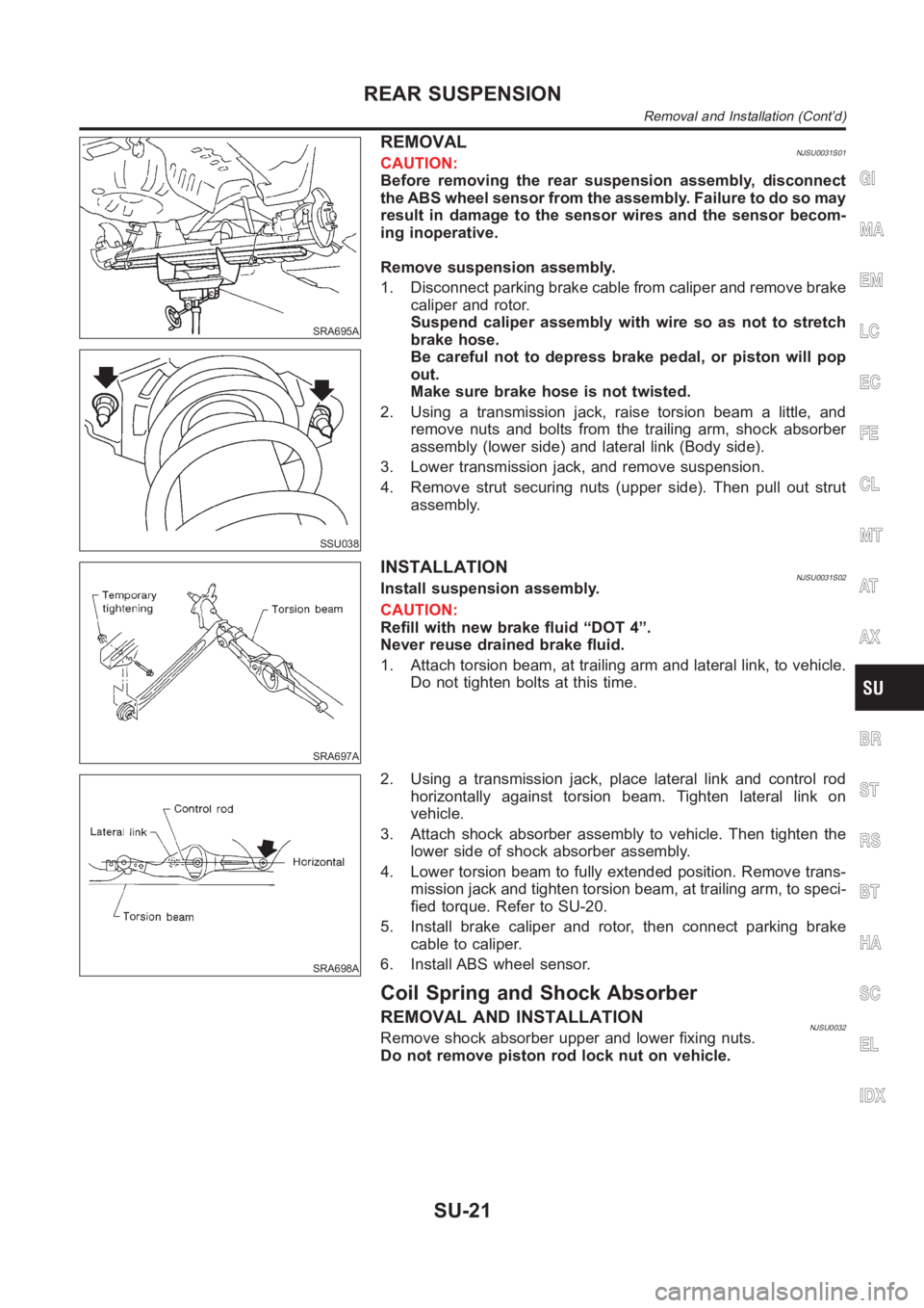
REMOVALNJSU0031S01CAUTION:
Before removing the rear suspension assembly, disconnect
the ABS wheel sensor from the assembly. Failure to do so may
result in damage to the sensor wires and the sensor becom-
ing inoperative.
Remove suspension assembly.
1. Disconnect parking brake cable from caliper and remove brake
caliper and rotor.
Suspend caliper assembly with wire so as not to stretch
brake hose.
Be careful not to depress brake pedal, or piston will pop
out.
Make sure brake hose is not twisted.
2. Using a transmission jack, raise torsion beam a little, and
remove nuts and bolts from the trailing arm, shock absorber
assembly (lower side) and lateral link (Body side).
3. Lower transmission jack, and remove suspension.
4. Remove strut securing nuts (upper side). Then pull out strut
assembly.
SRA697A
INSTALLATIONNJSU0031S02Install suspension assembly.
CAUTION:
Refill with new brake fluid “DOT 4”.
Never reuse drained brake fluid.
1. Attach torsion beam, at trailing arm and lateral link, to vehicle.
Do not tighten bolts at this time.
SRA698A
2. Using a transmission jack, place lateral link and control rod
horizontally against torsion beam. Tighten lateral link on
vehicle.
3. Attach shock absorber assembly to vehicle. Then tighten the
lower side of shock absorber assembly.
4. Lower torsion beam to fully extended position. Remove trans-
mission jack and tighten torsion beam, at trailing arm, to speci-
fied torque. Refer to SU-20.
5. Install brake caliper and rotor, then connect parking brake
cable to caliper.
6. Install ABS wheel sensor.
Coil Spring and Shock Absorber
REMOVAL AND INSTALLATIONNJSU0032Remove shock absorber upper and lower fixing nuts.
Do not remove piston rod lock nut on vehicle.
GI
MA
EM
LC
EC
FE
CL
MT
AT
AX
BR
ST
RS
BT
HA
SC
EL
IDX
REAR SUSPENSION
Removal and Installation (Cont’d)
SU-21
Page 2182 of 3189
SRA702A
3. Place lateral link and control rod horizontally against torsion
beam, and tighten to the specified torque.
4. Install torsion beam assembly. Refer to “Removal and
Installation”, “REAR SUSPENSION”, SU-21.
REAR SUSPENSION
Torsion Beam, Lateral Link and Control Rod (Cont’d)
SU-24
Page 2187 of 3189

Supplemental Restraint System (SRS) “AIR
BAG” and “SEAT BELT PRE-TENSIONER”
NJBR0139The Supplemental Restraint System such as “AIR BAG” and “SEAT BELT PRE-TENSIONER” used along with
a seat belt, helps to reduce the risk or severity of injury to the driver and front passenger for certain types of
collision. The SRS system composition which is available to NISSAN MODEL N16 is as follows (The compo-
sition varies according to the destination and optional equipment.):
For a frontal collision
The Supplemental Restraint System consists of driver air bag module (located in the center of the steer-
ing wheel), front passenger air bag module (located on the instrument panel on passenger side), front seat
belt pre-tensioners, a diagnosis sensor unit, warning lamp, wiring harness and spiral cable.
For a side collision
The Supplemental Restraint System consists of front side air bag module (located in the outer side of front
seat), side air bag (satellite) sensor, diagnosis sensor unit (one of components of air bags for a frontal
collision), wiring harness, warning lamp (one of components of air bags for a frontal collision).
Information necessary to service the system safely is included in theRS sectionof this Service Manual.
WARNING:
To avoid rendering the SRS inoperative, which could increase the risk of personal injury or death
in the event of a collision which would result in air bag inflation, all maintenance should be per-
formed by an authorized NISSAN dealer.
Improper maintenance, including incorrect removal and installation of the SRS, can lead to per-
sonal injury caused by unintentional activation of the system. For removalofSpiralCableandAir
Bag Module, see the RS section.
Do not use electrical test equipment on any circuit related to the SRS unless instructed to in this
Service Manual. SRS wiring harnesses can be identified by yellow or/and orange harness connec-
tor.
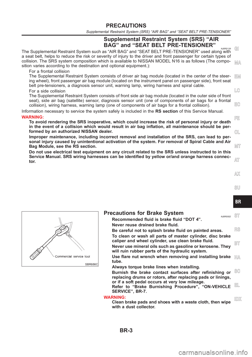
SBR686C
Precautions for Brake SystemNJBR0002Recommended fluid is brake fluid “DOT 4”.
Never reuse drained brake fluid.
Be careful not to splash brake fluid on painted areas.
To clean or wash all parts of master cylinder, disc brake
caliper and wheel cylinder, use clean brake fluid.
Never use mineral oils such as gasoline or kerosene. They
will ruin rubber parts of the hydraulic system.
Use flare nut wrench when removing and installing brake
tube.
Always torque brake lines when installing.
Burnish the brake contact surfaces after refinishing or
replacing drums or rotors, after replacing pads or linings,
or if a soft pedal occurs at very low mileage.
Refer to “Brake Burnishing Procedure”, “ON-VEHICLE
SERVICE”, BR-7.
WARNING:
Clean brake pads and shoes with a waste cloth, then wipe
with a dust collector.
GI
MA
EM
LC
EC
FE
CL
MT
AT
AX
SU
ST
RS
BT
HA
SC
EL
IDX
PRECAUTIONS
Supplemental Restraint System (SRS) “AIR BAG” and “SEAT BELT PRE-TENSIONER”
BR-3
Page 2189 of 3189
Commercial Service ToolsNJBR0004
Tool name Description
1 Flare nut crowfoot
2 Torque wrench
NT360
Removing and installing each brake piping
a: 10 mm (0.39 in)
Brake fluid pressure
gauge
NT151
Measuring brake fluid pressure
GI
MA
EM
LC
EC
FE
CL
MT
AT
AX
SU
ST
RS
BT
HA
SC
EL
IDX
PREPARATION
Commercial Service Tools
BR-5
Page 2200 of 3189
SBR704C
InstallationNJBR0155CAUTION:
Refill with new brake fluid “DOT 4”.
Never reuse drained brake fluid.
1. Place master cylinder onto brake booster and secure mount-
ing nuts lightly.
2. Torque mounting nuts.
:12-15N·m(1.2-1.5kg-m,9-11ft-lb)
3. Fill up reservoir tank with new brake fluid.
4. Plug all ports on master cylinder with fingers to prevent air
suction while releasing brake pedal.
5. Have driver depress brake pedal slowly several times until no
air comes out of master cylinder.
6. Fit brake lines to master cylinder.
7. Tighten flare nuts.
: 15 - 18 N·m (1.5 - 1.8 kg-m, 11 - 13 ft-lb)
8. Bleed air from brake system. Refer to “Bleeding Brake
System”, BR-8.
MASTER CYLINDER (NABCO)
Installation
BR-16
Page 2203 of 3189
SBR236E
InstallationNJBR0121CAUTION:
Refill with new brake fluid “DOT 4”.
Never reuse drained brake fluid.
1. Place master cylinder onto brake booster and secure mount-
ing nuts lightly.
2. Torque mounting nuts.
:13-15N·m(1.3-1.5kg-m,9-11ft-lb)
3. Fill up reservoir tank with new brake fluid.
4. Plug all ports on master cylinder with fingers to prevent air
suction while releasing brake pedal.
5. Have driver depress brake pedal slowly several times until no
air comes out of master cylinder.
6. Fit brake lines to master cylinder.
7. Tighten flare nuts.
: 15 - 18 N·m (1.5 - 1.8 kg-m, 11 - 13 ft-lb)
8. Bleed air from brake system.
GI
MA
EM
LC
EC
FE
CL
MT
AT
AX
SU
ST
RS
BT
HA
SC
EL
IDX
MASTER CYLINDER [BOSCH (NABCO)]
Installation
BR-19
Page 2211 of 3189

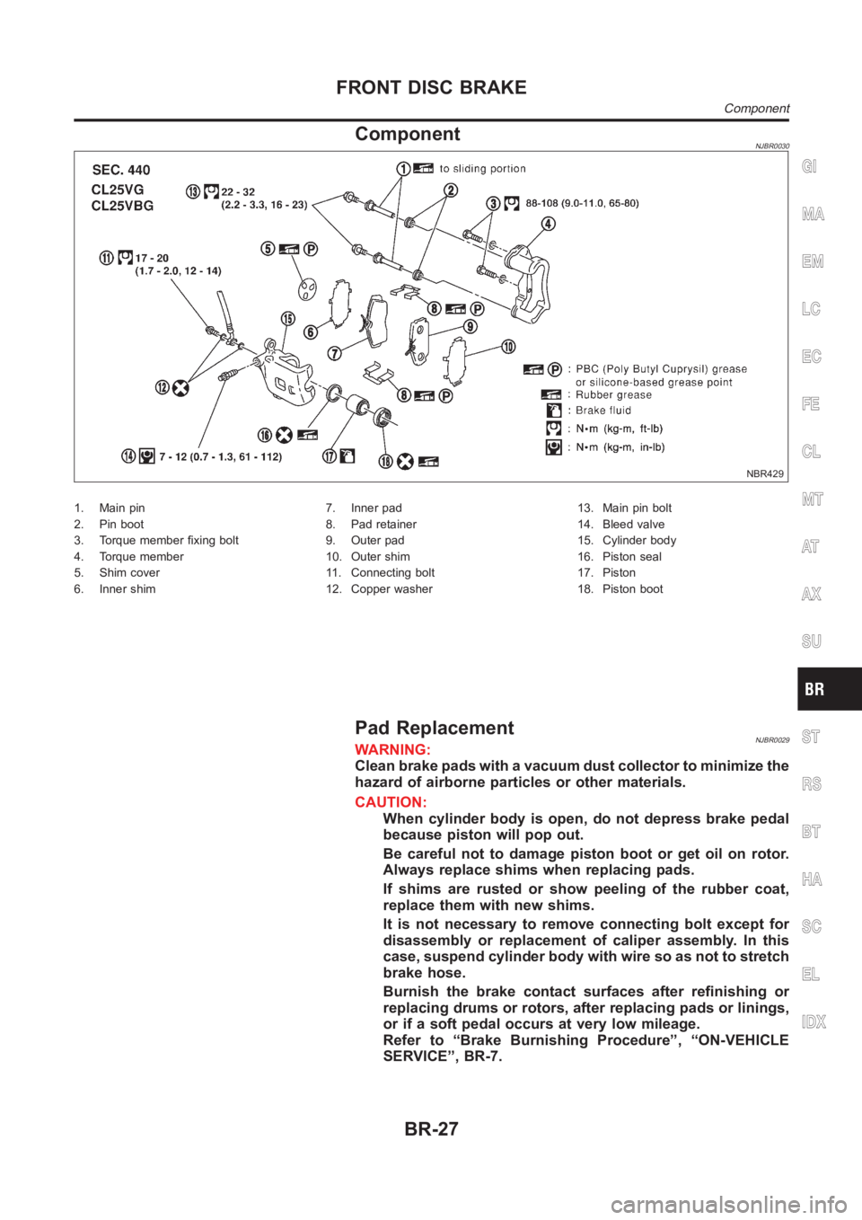
ComponentNJBR0030
NBR429
1. Main pin
2. Pin boot
3. Torque member fixing bolt
4. Torque member
5. Shim cover
6. Inner shim7. Inner pad
8. Pad retainer
9. Outer pad
10. Outer shim
11. Connecting bolt
12. Copper washer13. Main pin bolt
14. Bleed valve
15. Cylinder body
16. Piston seal
17. Piston
18. Piston boot
Pad ReplacementNJBR0029WARNING:
Clean brake pads with a vacuum dust collector to minimize the
hazard of airborne particles or other materials.
CAUTION:
When cylinder body is open, do not depress brake pedal
because piston will pop out.
Be careful not to damage piston boot or get oil on rotor.
Always replace shims when replacing pads.
If shims are rusted or show peeling of the rubber coat,
replace them with new shims.
It is not necessary to remove connecting bolt except for
disassembly or replacement of caliper assembly. In this
case, suspend cylinder body with wire so as not to stretch
brake hose.
Burnish the brake contact surfaces after refinishing or
replacing drums or rotors, after replacing pads or linings,
or if a soft pedal occurs at very low mileage.
Refer to “Brake Burnishing Procedure”, “ON-VEHICLE
SERVICE”, BR-7.
GI
MA
EM
LC
EC
FE
CL
MT
AT
AX
SU
ST
RS
BT
HA
SC
EL
IDX
FRONT DISC BRAKE
Component
BR-27