Page 3025 of 3189
RJIA0842E
3. Install the lower cover, then slide evaporator to forward.
4. Install the expansion valve from engine compartment.
Expansion valve mounting bolts
Tightening torque:
2.9 - 5.0 N·m (0.30 - 0.50 kg-m, 26 - 44 in-lb)
Blower Unit
REMOVALNJHA0195
RHA676HA
1. Remove the instrument panel assembly. Refer to BT-25, “Instru-
ment Panel Assembly”.
2. Disconnect the blower motor and resistor connector.
3. Remove blower unit.
INSTALLATIONNJHA0196Install in the reverse order of removal.
GI
MA
EM
LC
EC
FE
CL
MT
AT
AX
SU
BR
ST
RS
BT
SC
EL
IDX
SERVICE PROCEDUREMANUAL
A/C Evaporator (Cont’d)
HA-89
Page 3135 of 3189
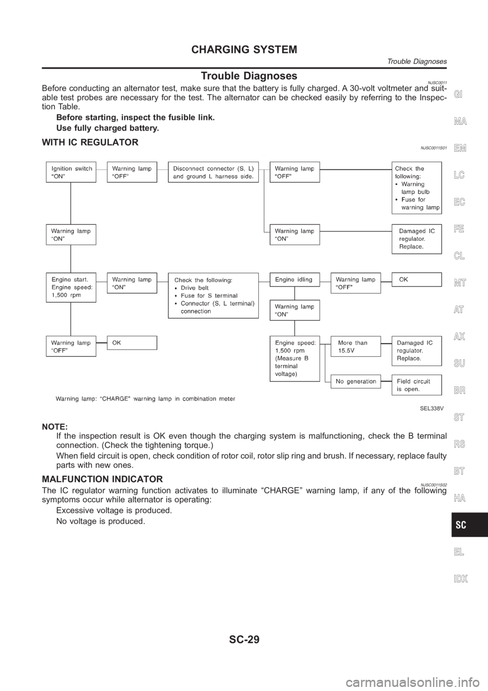
Trouble DiagnosesNJSC0011Before conducting an alternator test, make sure that the battery is fully charged. A 30-volt voltmeter and suit-
able test probes are necessary for the test. The alternator can be checked easily by referring to the Inspec-
tion Table.
Before starting, inspect the fusible link.
Use fully charged battery.
WITH IC REGULATORNJSC0011S01
SEL338V
NOTE:
If the inspection result is OK even though the charging system is malfunctioning, check the B terminal
connection. (Check the tightening torque.)
When field circuit is open, check condition of rotor coil, rotor slip ring and brush. If necessary, replace faulty
parts with new ones.
MALFUNCTION INDICATORNJSC0011S02The IC regulator warning function activates to illuminate “CHARGE” warning lamp, if any of the following
symptoms occur while alternator is operating:
Excessive voltage is produced.
No voltage is produced.
GI
MA
EM
LC
EC
FE
CL
MT
AT
AX
SU
BR
ST
RS
BT
HA
EL
IDX
CHARGING SYSTEM
Trouble Diagnoses
SC-29
Page 3147 of 3189
Special Service ToolsNJST0004
Tool number
Tool nameDescription
KV48100700
Torque adapter
NT169
Measuring pinion rotating torque
KV48102500
Pressure gauge adapter
NT542
Measuring oil pressure
ST27180001
Steering wheel puller
NT544
Removing steering wheel
HT72520000
Ball joint remover
NT546
Removing ball joint
a: 33 mm (1.30 in)
b: 50 mm (1.97 in)
r: R11.5 mm (0.453 in)
KV48103500
Pressure gauge
NT547
Measuring oil pressure
KV48104400
Rack seal ring reformer
NT550
Reforming teflon ring
a: 50 mm (1.97 in) dia.
b: 36 mm (1.42 in) dia.
c: 100 mm (3.94 in)
ST3127S000
1 GG91030000
Torque wrench
2 HT62940000
Socket adapter
3 HT62900000
Socket adapter
NT541
Measuring turning torque
GI
MA
EM
LC
EC
FE
CL
MT
AT
AX
SU
BR
RS
BT
HA
SC
EL
IDX
PREPARATION
Special Service Tools
ST-3
Page 3149 of 3189
NJST0006
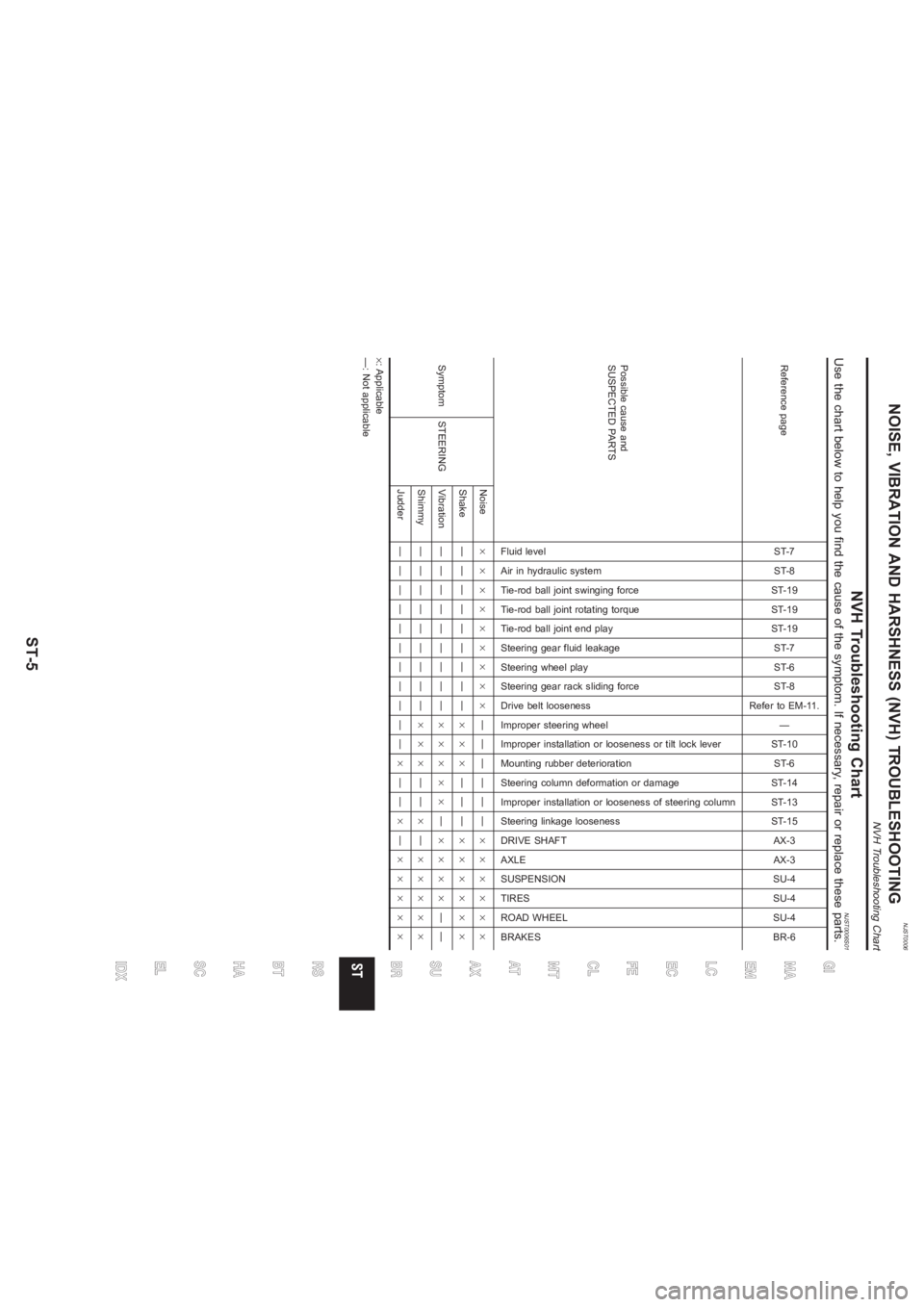
NVH Troubleshooting Chart
NJST0006S01
Use the chart below to help you find the cause of the symptom. If necessary, repair or replace these parts.Reference page
ST-7
ST-8
ST-19
ST-19
ST-19
ST-7
ST-6
ST-8
Refer to EM-11.
—
ST-10
ST-6
ST-14
ST-13
ST-15
AX-3
AX-3
SU-4
SU-4
SU-4
BR-6
Possible cause and
SUSPECTED PARTS
Fluid level
Air in hydraulic system
Tie-rod ball joint swinging force
Tie-rod ball joint rotating torque
Tie-rod ball joint end play
Steering gear fluid leakage
Steering wheel play
Steering gear rack sliding force
Drive belt looseness
Improper steering wheel
Improper installation or looseness or tilt lock lever
Mounting rubber deterioration
Steering column deformation or damage
Improper installation or looseness of steering column
Steering linkage looseness
DRIVE SHAFT
AXLE
SUSPENSION
TIRES
ROAD WHEEL
BRAKES
Symptom STEERINGNoise×××××××××——————××××××
Shake —————————×××———××××××
Vibration —————————×××××—××××——
Shimmy —————————×××——×—×××××
Judder———————————×——×—×××××
×: Applicable
—: Not applicable
GI
MA
EM
LC
EC
FE
CL
MT
AT
AX
SU
BRRS
BT
HA
SC
EL
IDX
NOISE, VIBRATION AND HARSHNESS (NVH) TROUBLESHOOTING
NVH Troubleshooting Chart
ST-5
Page 3161 of 3189
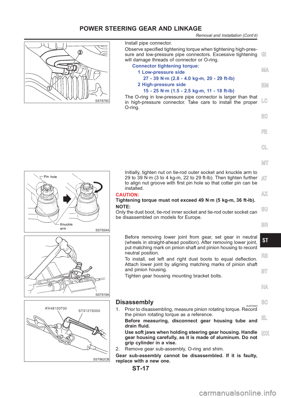
SST879C
Install pipe connector.
Observe specified tightening torque when tightening high-pres-
sure and low-pressure pipe connectors. Excessive tightening
will damage threads of connector or O-ring.
Connector tightening torque:
1 Low-pressure side
27 - 39 N·m (2.8 - 4.0 kg-m, 20 - 29 ft-lb)
2 High-pressure side
15 - 25 N·m (1.5 - 2.5 kg-m, 11 - 18 ft-lb)
The O-ring in low-pressure pipe connector is larger than that
in high-pressure connector. Take care to install the proper
O-ring.
SST824A
Initially, tighten nut on tie-rod outer socket and knuckle arm to
29 to 39 N·m (3 to 4 kg-m, 22 to 29 ft-lb). Then tighten further
to align nut groove with first pin hole so that cotter pin can be
installed.
CAUTION:
Tightening torque must not exceed 49 N·m (5 kg-m, 36 ft-lb).
NOTE:
Only the dust boot, tie-rod inner socket and tie-rod outer socket can
be disassembled on models for Europe.
SST819A
Before removing lower joint from gear, set gear in neutral
(wheels in straight-ahead position). After removing lower joint,
put matching mark on pinion shaft and pinion housing to record
neutral position.
To install, set left and right dust boots to equal deflection.
Attach lower joint by aligning matching marks of pinion shaft
and pinion housing.
Tighten gear housing mounting bracket bolts.
SST862CB
DisassemblyNJST00231. Prior to disassembling, measure pinion rotating torque. Record
the pinion rotating torque as a reference.
Before measuring, disconnect gear housing tube and
drain fluid.
Use soft jaws when holding steering gear housing. Handle
gear housing carefully, as it is made of aluminum. Do not
grip cylinder in a vise.
2. Remove gear sub-assembly, O-ring and shim.
Gear sub-assembly cannot be disassembled. If it is faulty,
replace with a new one.
GI
MA
EM
LC
EC
FE
CL
MT
AT
AX
SU
BR
RS
BT
HA
SC
EL
IDX
POWER STEERING GEAR AND LINKAGE
Removal and Installation (Cont’d)
ST-17
Page 3162 of 3189
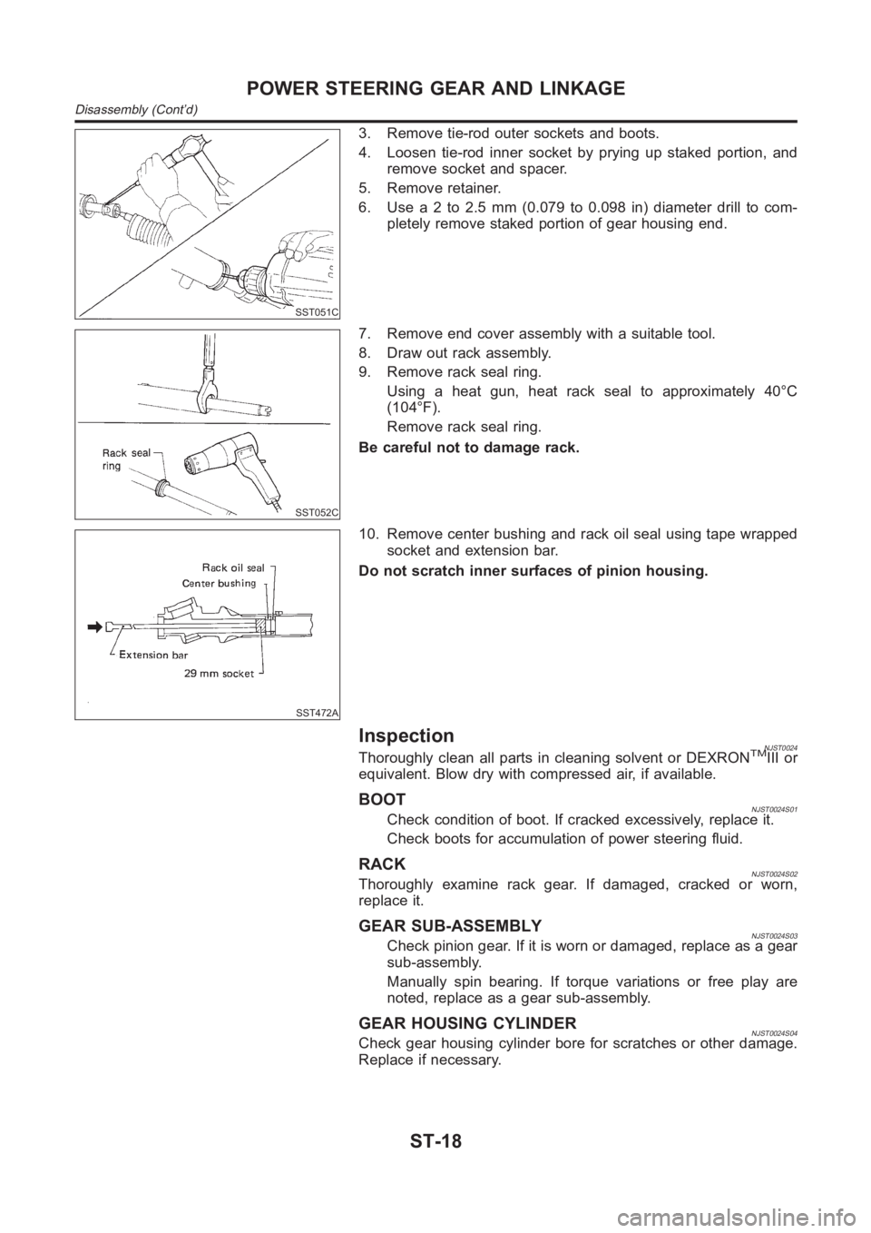
SST051C
3. Remove tie-rod outer sockets and boots.
4. Loosen tie-rod inner socket by prying up staked portion, and
remove socket and spacer.
5. Remove retainer.
6. Use a 2 to 2.5 mm (0.079 to 0.098 in) diameter drill to com-
pletely remove staked portion of gear housing end.
SST052C
7. Remove end cover assembly with a suitable tool.
8. Draw out rack assembly.
9. Remove rack seal ring.
Using a heat gun, heat rack seal to approximately 40°C
(104°F).
Remove rack seal ring.
Be careful not to damage rack.
SST472A
10. Remove center bushing and rack oil seal using tape wrapped
socket and extension bar.
Do not scratch inner surfaces of pinion housing.
InspectionNJST0024Thoroughly clean all parts in cleaning solvent or DEXRONTMIII or
equivalent. Blow dry with compressed air, if available.
BOOTNJST0024S01Check condition of boot. If cracked excessively, replace it.
Check boots for accumulation of power steering fluid.
RACKNJST0024S02Thoroughly examine rack gear. If damaged, cracked or worn,
replace it.
GEAR SUB-ASSEMBLYNJST0024S03Check pinion gear. If it is worn or damaged, replace as a gear
sub-assembly.
Manually spin bearing. If torque variations or free play are
noted, replace as a gear sub-assembly.
GEAR HOUSING CYLINDERNJST0024S04Check gear housing cylinder bore for scratches or other damage.
Replace if necessary.
POWER STEERING GEAR AND LINKAGE
Disassembly (Cont’d)
ST-18
Page 3163 of 3189
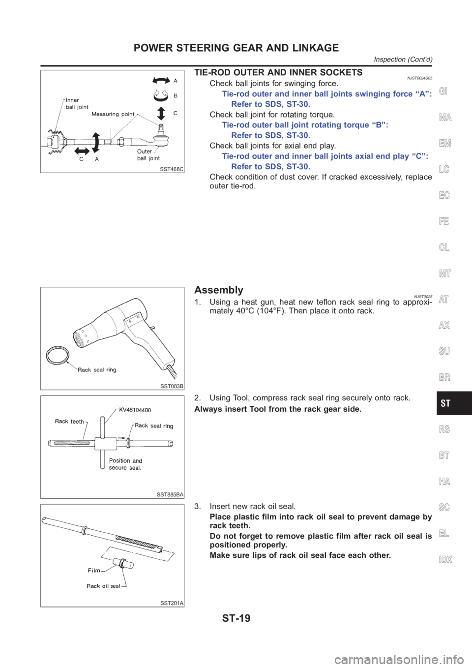
SST468C
TIE-ROD OUTER AND INNER SOCKETSNJST0024S05Check ball joints for swinging force.
Tie-rod outer and inner ball joints swinging force “A”:
Refer to SDS, ST-30.
Check ball joint for rotating torque.
Tie-rod outer ball joint rotating torque “B”:
Refer to SDS, ST-30.
Check ball joints for axial end play.
Tie-rod outer and inner ball joints axial end play “C”:
Refer to SDS, ST-30.
Check condition of dust cover. If cracked excessively, replace
outer tie-rod.
SST083B
AssemblyNJST00251. Using a heat gun, heat new teflon rack seal ring to approxi-
mately 40°C (104°F). Then place it onto rack.
SST885BA
2. Using Tool, compress rack seal ring securely onto rack.
Always insert Tool from the rack gear side.
SST201A
3. Insert new rack oil seal.
Place plastic film into rack oil seal to prevent damage by
rack teeth.
Do not forget to remove plastic film after rack oil seal is
positioned properly.
Make sure lips of rack oil seal face each other.
GI
MA
EM
LC
EC
FE
CL
MT
AT
AX
SU
BR
RS
BT
HA
SC
EL
IDX
POWER STEERING GEAR AND LINKAGE
Inspection (Cont’d)
ST-19
Page 3164 of 3189
SST863C
4. Install center bushing and rack oil seal with rack assembly.
SST321B
5. Insert rack oil seal and end cover assembly to rack. Then
tighten end cover assembly.
SST073B
6. Fasten end cover assembly to gear housing by staking.
SST086BA
7. Set rack gear in neutral position.
Rack stroke “S”:
Refer to SDS, ST-30.
SST880C
8. Install adjustment shims and O-rings to gear sub-assembly.
Install the same number of adjustment shims as before,
regardless of whether or not gear sub-assembly is replaced.
Discard old O-rings; replace with new ones.
9. Tighten gear subassembly securing bolts to specified tighten-
ing torque.
POWER STEERING GEAR AND LINKAGE
Assembly (Cont’d)
ST-20