Page 2226 of 3189
SBR219C
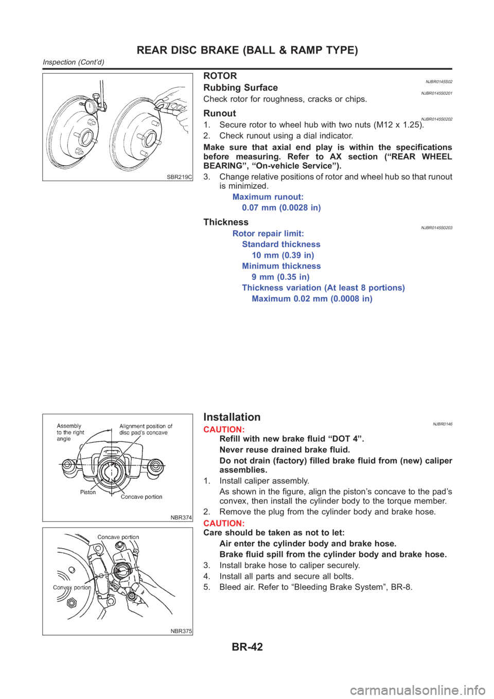
ROTORNJBR0145S02Rubbing SurfaceNJBR0145S0201Check rotor for roughness, cracks or chips.
RunoutNJBR0145S02021. Secure rotor to wheel hub with two nuts (M12 x 1.25).
2. Check runout using a dial indicator.
Make sure that axial end play is within the specifications
before measuring. Refer to AX section (“REAR WHEEL
BEARING”, “On-vehicle Service”).
3. Change relative positions of rotor and wheel hub so that runout
is minimized.
Maximum runout:
0.07 mm (0.0028 in)
ThicknessNJBR0145S0203Rotor repair limit:
Standard thickness
10 mm (0.39 in)
Minimum thickness
9 mm (0.35 in)
Thickness variation (At least 8 portions)
Maximum 0.02 mm (0.0008 in)
NBR374
NBR375
InstallationNJBR0146CAUTION:
Refill with new brake fluid “DOT 4”.
Never reuse drained brake fluid.
Do not drain (factory) filled brake fluid from (new) caliper
assemblies.
1. Install caliper assembly.
As shown in the figure, align the piston’s concave to the pad’s
convex, then install the cylinder body to the torque member.
2. Remove the plug from the cylinder body and brake hose.
CAUTION:
Care should be taken as not to let:
Air enter the cylinder body and brake hose.
Brake fluid spill from the cylinder body and brake hose.
3. Install brake hose to caliper securely.
4. Install all parts and secure all bolts.
5. Bleed air. Refer to “Bleeding Brake System”, BR-8.
REAR DISC BRAKE (BALL & RAMP TYPE)
Inspection (Cont’d)
BR-42
Page 2246 of 3189
YBR319
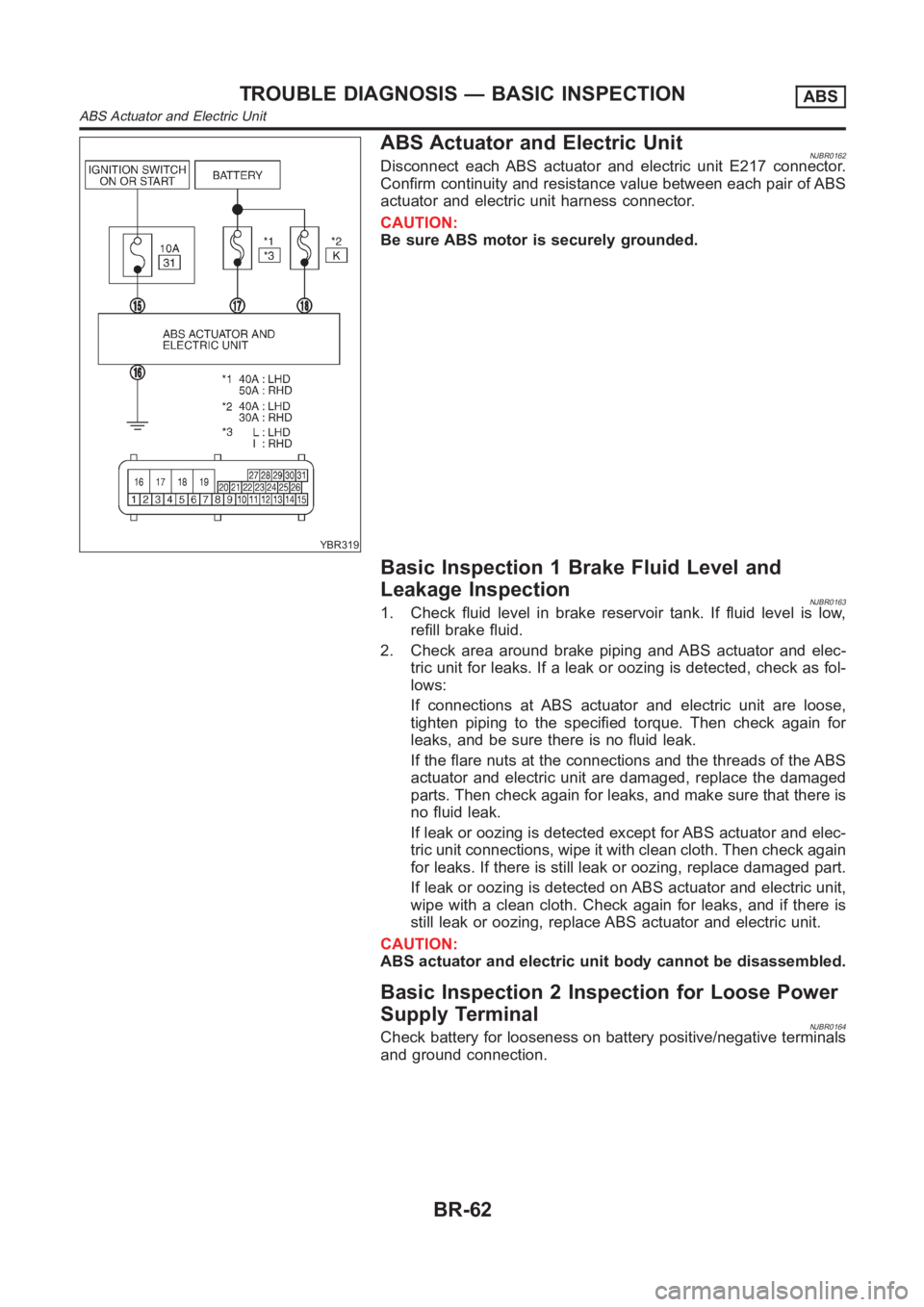
ABS Actuator and Electric UnitNJBR0162Disconnect each ABS actuator and electric unit E217 connector.
Confirm continuity and resistance value between each pair of ABS
actuator and electric unit harness connector.
CAUTION:
Be sure ABS motor is securely grounded.
Basic Inspection 1 Brake Fluid Level and
Leakage Inspection
NJBR01631. Check fluid level in brake reservoir tank. If fluid level is low,
refill brake fluid.
2. Check area around brake piping and ABS actuator and elec-
tric unit for leaks. If a leak or oozing is detected, check as fol-
lows:
If connections at ABS actuator and electric unit are loose,
tighten piping to the specified torque. Then check again for
leaks, and be sure there is no fluid leak.
If the flare nuts at the connections and the threads of the ABS
actuator and electric unit are damaged, replace the damaged
parts. Then check again for leaks, and make sure that there is
no fluid leak.
If leak or oozing is detected except for ABS actuator and elec-
tric unit connections, wipe it with clean cloth. Then check again
for leaks. If there is still leak or oozing, replace damaged part.
If leak or oozing is detected on ABS actuator and electric unit,
wipe with a clean cloth. Check again for leaks, and if there is
still leak or oozing, replace ABS actuator and electric unit.
CAUTION:
ABS actuator and electric unit body cannot be disassembled.
Basic Inspection 2 Inspection for Loose Power
Supply Terminal
NJBR0164Check battery for looseness on battery positive/negative terminals
and ground connection.
TROUBLE DIAGNOSIS — BASIC INSPECTIONABS
ABS Actuator and Electric Unit
BR-62
Page 2498 of 3189
SEL543TA
Removal and InstallationNJEL0060WIPER ARMSNJEL0060S011. Prior to wiper arm installation, turn on wiper switch to operate
wiper motor and then turn it “OFF” (Auto Stop).
2. Lift the blade up and then set it down onto glass surface to set
the blade center to clearance “L
1”&“L2” immediately before
tightening nut.
3. Eject washer fluid. Turn on wiper switch to operate wiper motor
and then turn it “OFF”.
4. Ensure that wiper blades stop within clearance “L
1”&“L2”.
Clearance “L1”:23-37mm(0.91-1.46in)
Clearance “L
2”:24-38mm(0.94-1.50in)
Tighten wiper arm nuts to specified torque.
Front wiper: 21 - 26 N·m (2.1 - 2.7 kg-m, 16 - 19 ft-lb)
SEL024J
Before reinstalling wiper arm, clean up the pivot area as
illustrated. This will reduce possibility of wiper arm loose-
ness.
WIPER LINKAGENJEL0060S02
NEL801
FRONT WIPER AND WASHER
Removal and Installation
EL-162
Page 2502 of 3189
SEL451XA
Removal and InstallationNJEL0301WIPER ARMSNJEL0301S011. Prior to wiper arm installation, turn on wiper switch to operate
wiper motor and then turn it “OFF” (Auto Stop).
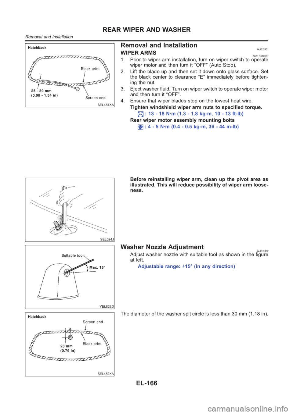
2. Lift the blade up and then set it down onto glass surface. Set
the black center to clearance “E” immediately before tighten-
ing the nut.
3. Eject washer fluid. Turn on wiper switch to operate wiper motor
and then turn it “OFF”.
4. Ensure that wiper blades stop on the lowest heat wire.
Tighten windshield wiper arm nuts to specified torque.
: 13 - 18 N·m (1.3 - 1.8 kg-m, 10 - 13 ft-lb)
Rear wiper motor assembly mounting bolts
: 4 - 5 N·m (0.4 - 0.5 kg-m, 36 - 44 in-lb)
SEL024J
Before reinstalling wiper arm, clean up the pivot area as
illustrated. This will reduce possibility of wiper arm loose-
ness.
YEL823D
Washer Nozzle AdjustmentNJEL0302Adjust washer nozzle with suitable tool as shown in the figure
at left.
Adjustable range:±15° (In any direction)
SEL452XA
The diameter of the washer spit circle is less than 30 mm (1.18 in).
REAR WIPER AND WASHER
Removal and Installation
EL-166
Page 2936 of 3189
Code Section Wiring Diagram Name
NAVI EL Navigation System
NONDTC AT Non-detectable Items
O2H1B1 EC Front Heated Oxygen Sensor Heater
(E-OBD)
O2H2B1 EC Rear Heated Oxygen Sensor Heater
(E-OBD)
O2S1B1 EC Front Heated Oxygen Sensor
(E-OBD)
O2S2B1 EC Rear Heated Oxygen Sensor
(E-OBD)
OVRCSV AT Overrun Clutch Solenoid Valve
PGC/V EC EVAP Canister Purge Volume Con-
trol Solenoid Valve
PHASE EC Camshaft Position Sensor (PHASE)
PNP/SW EC Park/Neutral Position Switch
PNP/SW AT Park/Neutral Position Switch
PNPSW1 EC Park/Neutral Position Switch
POS EC Crankshaft Position Sensor (POS)
POWER EL Power Supply Routing
PRGVLV EC EVAP Canister Purge Volume Con-
trol Solenoid Valve
PST/SW EC Power Steering Oil Pressure Switch
R/FOG EL Rear Fog Lamp
ROOM/L EL Interior Room Lamp
RP/SEN EC Refrigerant Pressure Sensor
RRO2 EC Rear Heated Oxygen Sensor (Non
E-OBD)
RRO2/H EC Rear Heated Oxygen Sensor Heater
(Non E-OBD)
S/SIG EC Start Signal
SHIFT AT A/T Shift Lock System
S/LOCK EL Power Door Lock — Super Lock —
SROOF EL Sunroof
SRS RS Supplemental Restraint System
SSV/A AT Shift Solenoid Valve A
SSV/B AT Shift Solenoid Valve B
START SC Starting System
STOP/L EL Stop Lamp
TAIL/L EL Parking, License and Tail Lamps
TCV AT Torque Converter Clutch Solenoid
Valve
TPS AT Throttle Position SensorCode Section Wiring Diagram Name
TPS EC Throttle Position Sensor
TURN EL Turn Signal and Hazard Warning
Lamps
VSS EC Vehicle Speed Sensor
VSSA/T AT Vehicle Speed Sensor A/T (Revolu-
tion Sensor)
VSSMTR AT Vehicle Speed Sensor MTR
WARN EL Warning Lamps
WINDOW EL Power Window
WIP/R EL Rear Wiper and Washer
WIPER EL Front Wiper and Washer
WIRING DIAGRAM CODES (CELL CODES)
EL-600
Page 2940 of 3189
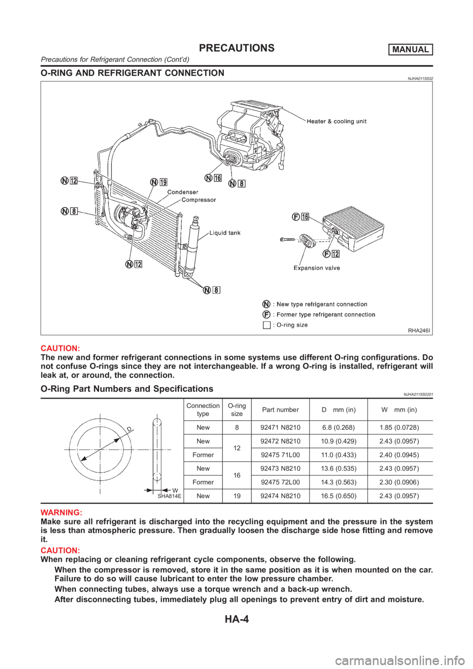
O-RING AND REFRIGERANT CONNECTIONNJHA0115S02
RHA246I
CAUTION:
The new and former refrigerant connections in some systems use different O-ring configurations. Do
not confuse O-rings since they are not interchangeable. If a wrong O-ring is installed, refrigerant will
leak at, or around, the connection.
O-Ring Part Numbers and SpecificationsNJHA0115S0201
SHA814E
Connection
typeO-ring
sizePart number D mm (in) W mm (in)
New 8 92471 N8210 6.8 (0.268) 1.85 (0.0728)
New
1292472 N8210 10.9 (0.429) 2.43 (0.0957)
Former 92475 71L00 11.0 (0.433) 2.40 (0.0945)
New
1692473 N8210 13.6 (0.535) 2.43 (0.0957)
Former 92475 72L00 14.3 (0.563) 2.30 (0.0906)
New 19 92474 N8210 16.5 (0.650) 2.43 (0.0957)
WARNING:
Make sure all refrigerant is discharged into the recycling equipment and the pressure in the system
is less than atmospheric pressure. Then gradually loosen the discharge side hose fitting and remove
it.
CAUTION:
When replacing or cleaning refrigerant cycle components, observe the following.
When the compressor is removed, store it in the same position as it is when mounted on the car.
Failure to do so will cause lubricant to enter the low pressure chamber.
When connecting tubes, always use a torque wrench and a back-up wrench.
After disconnecting tubes, immediately plug all openings to prevent entry of dirt and moisture.
PRECAUTIONSMANUAL
Precautions for Refrigerant Connection (Cont’d)
HA-4
Page 2941 of 3189
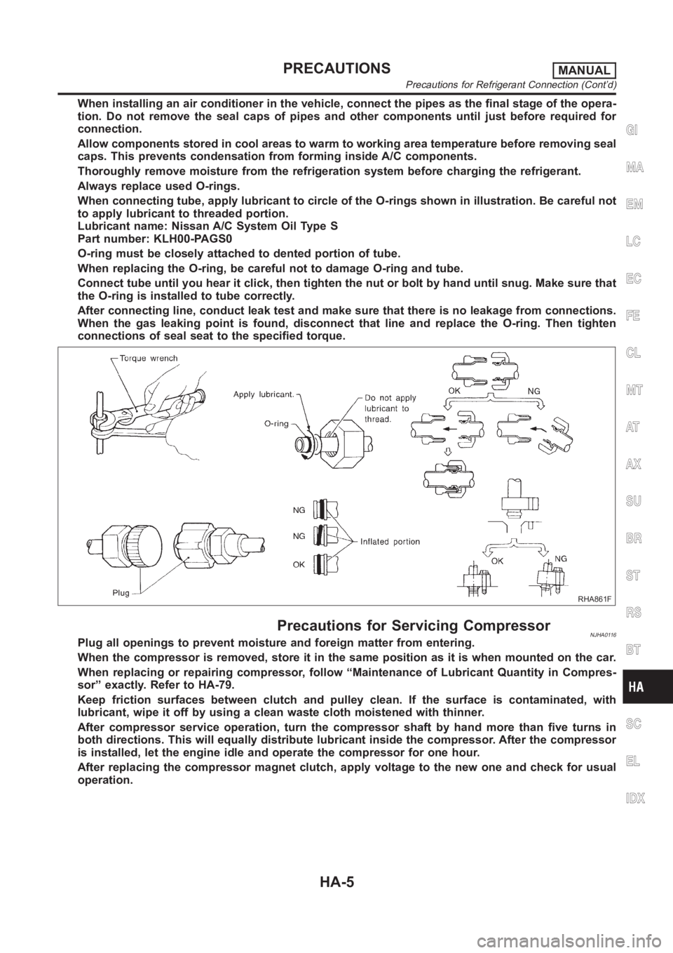
When installing an air conditioner in the vehicle, connect the pipes as thefinal stage of the opera-
tion. Do not remove the seal caps of pipes and other components until just before required for
connection.
Allow components stored in cool areas to warm to working area temperature before removing seal
caps. This prevents condensation from forming inside A/C components.
Thoroughly remove moisture from the refrigeration system before charging the refrigerant.
Always replace used O-rings.
When connecting tube, apply lubricant to circle of the O-rings shown in illustration. Be careful not
to apply lubricant to threaded portion.
Lubricant name: Nissan A/C System Oil Type S
Part number: KLH00-PAGS0
O-ring must be closely attached to dented portion of tube.
When replacing the O-ring, be careful not to damage O-ring and tube.
Connect tube until you hear it click, then tighten the nut or bolt by hand until snug. Make sure that
the O-ring is installed to tube correctly.
After connecting line, conduct leak test and make sure that there is no leakage from connections.
When the gas leaking point is found, disconnect that line and replace the O-ring. Then tighten
connections of seal seat to the specified torque.
RHA861F
Precautions for Servicing CompressorNJHA0116Plug all openings to prevent moisture and foreign matter from entering.
When the compressor is removed, store it in the same position as it is when mounted on the car.
When replacing or repairing compressor, follow “Maintenance of Lubricant Quantity in Compres-
sor” exactly. Refer to HA-79.
Keep friction surfaces between clutch and pulley clean. If the surface is contaminated, with
lubricant, wipe it off by using a clean waste cloth moistened with thinner.
After compressor service operation, turn the compressor shaft by hand more than five turns in
both directions. This will equally distribute lubricant inside the compressor. After the compressor
is installed, let the engine idle and operate the compressor for one hour.
After replacing the compressor magnet clutch, apply voltage to the new oneand check for usual
operation.
GI
MA
EM
LC
EC
FE
CL
MT
AT
AX
SU
BR
ST
RS
BT
SC
EL
IDX
PRECAUTIONSMANUAL
Precautions for Refrigerant Connection (Cont’d)
HA-5
Page 3022 of 3189
RHA143E
Install the pulley assembly using the installer and a hand
press, and then install the snap ring using snap ring pliers.
RHA127F
Install the clutch disc on the drive shaft, together with the
original shim(s). Press the clutch disc down by hand.
RHA086E
Using the holder to prevent clutch disc rotation, tighten the bolt
to 14 N·m (1.4 kg-m, 10 ft-lb) torque.
After tightening the bolt, check that the pulley rotates
smoothly.
RHA087E
Check clearance around the entire periphery of clutch disc.
Disc-to-pulley clearance:
0.3 - 0.6 mm (0.012 - 0.024 in)
If the specified clearance is not obtained, replace adjusting
spacer and readjust.
Break-in OperationNJHA0214S01When replacing compressor clutch assembly, always carry out the
break-in operation. This is done by engaging and disengaging the
clutch about thirty times. Break-in operation raises the level of
transmitted torque.
SERVICE PROCEDUREMANUAL
Compressor Clutch — CSV613 (CALSONIC make) (Cont’d)
HA-86