2003 NISSAN ALMERA N16 torque
[x] Cancel search: torquePage 1976 of 3189
![NISSAN ALMERA N16 2003 Electronic Repair Manual AT-520
[ALL]
SERVICE DATA AND SPECIFICATIONS (SDS)
TABLE FOR SELECTING DIFFERENTIAL SIDE BEARING ADJUSTING SHIMS (FOR RE4F03B)
Unit: mm (in)
Reduction Pinion GearECS007U3
BEARING PRELOAD
TURNING TORQU NISSAN ALMERA N16 2003 Electronic Repair Manual AT-520
[ALL]
SERVICE DATA AND SPECIFICATIONS (SDS)
TABLE FOR SELECTING DIFFERENTIAL SIDE BEARING ADJUSTING SHIMS (FOR RE4F03B)
Unit: mm (in)
Reduction Pinion GearECS007U3
BEARING PRELOAD
TURNING TORQU](/manual-img/5/57350/w960_57350-1975.png)
AT-520
[ALL]
SERVICE DATA AND SPECIFICATIONS (SDS)
TABLE FOR SELECTING DIFFERENTIAL SIDE BEARING ADJUSTING SHIMS (FOR RE4F03B)
Unit: mm (in)
Reduction Pinion GearECS007U3
BEARING PRELOAD
TURNING TORQUE
Dial indicator deflection Suitable shim(s)
0.31 - 0.35 (0.0122 - 0.0138)
0.35 - 0.39 (0.0138 - 0.0154)
0.39 - 0.43 (0.0154 - 0.0169)
0.43 - 0.47 (0.0169 - 0.0185)
0.47 - 0.51 (0.0185 - 0.0201)
0.51 - 0.55 (0.0201 - 0.0217)
0.55 - 0.59 (0.0217 - 0.0232)
0.59 - 0.63 (0.0232 - 0.0248)
0.63 - 0.67 (0.0248 - 0.0264)
0.67 - 0.71 (0.0264 - 0.0280)
0.71 - 0.75 (0.0280 - 0.0295)
0.75 - 0.79 (0.0295 - 0.0311)
0.79 - 0.83 (0.0311 - 0.0327)
0.83 - 0.87 (0.0327 - 0.0343)
0.87 - 0.91 (0.0343 - 0.0358)
0.91 - 0.95 (0.0358 - 0.0374)
0.95 - 0.99 (0.0374 - 0.0390)
0.99 - 1.03 (0.0390 - 0.0406)
1.03 - 1.07 (0.0406 - 0.0421)
1.07 - 1.11 (0.0421 - 0.0437)
1.11 - 1.15 (0.0437 - 0.0453)
1.15 - 1.19 (0.0453 - 0.0469)
1.19 - 1.23 (0.0469 - 0.0484)
1.23 - 1.27 (0.0484 - 0.0500)
1.27 - 1.31 (0.0500 - 0.0516)
1.31 - 1.35 (0.0516 - 0.0531)
1.35 - 1.39 (0.0531 - 0.0547)
1.39 - 1.43 (0.0547 - 0.0563)
1.43 - 1.47 (0.0563 - 0.0579)
1.47 - 1.51 (0.0579 - 0.0594)
1.51 - 1.55 (0.0594 - 0.0610)
1.55 - 1.59 (0.0610 - 0.0626)
1.59 - 1.63 (0.0626 - 0.0642)
1.63 - 1.67 (0.0642 - 0.0657)
1.67 - 1.71 (0.0657 - 0.0673)
1.71 - 1.75 (0.0673 - 0.0689)
1.75 - 1.79 (0.0689 - 0.0705)
1.79 - 1.83 (0.0705 - 0.0720)
1.83 - 1.87 (0.0720 - 0.0736)
1.87 - 1.91 (0.0736 - 0.0752)
1.91 - 1.95 (0.0752 - 0.0768)0.40 (0.0157)
0.44 (0.0173)
0.48 (0.0189)
0.52 (0.0205)
0.56 (0.0220)
0.60 (0.0236)
0.64 (0.0252)
0.68 (0.0268)
0.72 (0.0283)
0.76 (0.0299)
0.80 (0.0315)
0.84 (0.0331)
0.88 (0.0346)
0.92 (0.0362)
0.48 (0.0189) + 0.48 (0.0189)
0.48 (0.0189) + 0.52 (0.0205)
0.52 (0.0205) + 0.52 (0.0205)
0.52 (0.0205) + 0.56 (0.0220)
0.56 (0.0220) + 0.56 (0.0220)
0.56 (0.0220) + 0.60 (0.0236)
0.60 (0.0236) + 0.60 (0.0236)
0.60 (0.0236) + 0.64 (0.0252)
0.64 (0.0252) + 0.64 (0.0252)
0.64 (0.0252) + 0.68 (0.0268)
0.68 (0.0268) + 0.68 (0.0268)
0.68 (0.0268) + 0.72 (0.0283)
1.44 (0.0567)
0.72 (0.0283) + 0.76 (0.0299)
0.76 (0.0299) + 0.76 (0.0299)
0.76 (0.0299) + 0.80 (0.0315)
0.80 (0.0315) + 0.80 (0.0315)
0.80 (0.0315) + 0.84 (0.0331)
0.84 (0.0331) + 0.84 (0.0331)
0.84 (0.0331) + 0.88 (0.0346)
0.88 (0.0346) + 0.88 (0.0346)
0.88 (0.0346) + 0.92 (0.0362)
0.92 (0.0362) + 0.92 (0.0362)
0.92 (0.0362) + 0.96 (0.0378)
0.96 (0.0378) + 0.96 (0.0378)
0.52 (0.0205) + 1.44 (0.0567)
0.56 (0.0220) + 1.44 (0.0567)
Reduction pinion gear bearing preload 0.05 mm (0.0020 in)
Turning torque of reduction pinion gear 0.1 - 0.69 N-m (1.1 - 7.0 kg-cm, 0.95 - 6.08 in-lb)
Page 1980 of 3189
![NISSAN ALMERA N16 2003 Electronic Repair Manual AT-524
[ALL]
SERVICE DATA AND SPECIFICATIONS (SDS)
Band Servo
ECS007U9
RETURN SPRING
Unit: mm (in)
*: Always check with the Parts Department for the latest parts information.
Removal and InstallationE NISSAN ALMERA N16 2003 Electronic Repair Manual AT-524
[ALL]
SERVICE DATA AND SPECIFICATIONS (SDS)
Band Servo
ECS007U9
RETURN SPRING
Unit: mm (in)
*: Always check with the Parts Department for the latest parts information.
Removal and InstallationE](/manual-img/5/57350/w960_57350-1979.png)
AT-524
[ALL]
SERVICE DATA AND SPECIFICATIONS (SDS)
Band Servo
ECS007U9
RETURN SPRING
Unit: mm (in)
*: Always check with the Parts Department for the latest parts information.
Removal and InstallationECS007UA
Unit: mm (in)
Shift Solenoid ValvesECS007UB
Solenoid ValvesECS007UC
A/T Fluid Temperature SensorECS007UD
Remarks: Specification data are reference values.
Revolution SensorECS007UE
Dropping ResistorECS007UF
Return spring Free length Outer diameter Part number*
2nd servo return spring 32.5 (1.280) 25.9 (1.020) 31605-31X20
OD servo return spring 38.52 (1.5165) 22.0 (0.866) 31605-31X21
Distance between end of converter housing and torque converter 21.1 (0.831) or more
Gear Solenoid A Solenoid B
1st ON ON
2nd OFF ON
3rd OFF OFF
4th ON OFF
Solenoid valve Resistance (Approx.) Terminal number
Shift solenoid A 20 - 30Ω2
Shift solenoid B 5 - 20Ω1
Ovr. clutch sol. 20 - 30Ω3
Line pres. sol. 2.5 - 5Ω4
T/conv. clutch sol. 5 - 20Ω5
Monitor item Condition Specification (Approximately)
A/T fluid temperature sensorCold [20°C (68°F)]
↓
Hot [80°C (176°F)]1.5V
↓
0.5V2.5 kΩ
↓
0.3 kΩ
Condition Judgement standard
When moving at 20 km/h (12 MPH), use the CONSULT-II pulse frequency measuring func-
tion.*1
CAUTION:
Connect the diagnosis data link cable to the vehicle diagnosis connector.
*1: A circuit tester cannot be used to test this item.150 Hz (Approx.)
When vehicle parks.Under 1.3V or over 4.5V
Resistance10 - 15Ω
Page 1986 of 3189
ATC-6
PRECAUTIONS
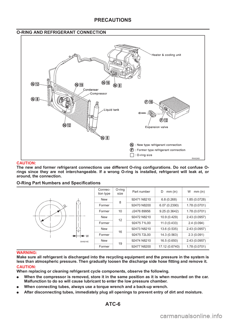
O-RING AND REFRIGERANT CONNECTION
CAUTION:
The new and former refrigerant connections use different O-ring configurations. Do not confuse O-
rings since they are not interchangeable. If a wrong O-ring is installed, refrigerant will leak at, or
around, the connection.
O-Ring Part Numbers and Specifications
WARNING:
Make sure all refrigerant is discharged into the recycling equipment and the pressure in the system is
less than atmospheric pressure. Then gradually loosen the discharge side hose fitting and remove it.
CAUTION:
When replacing or cleaning refrigerant cycle components, observe the following.
●When the compressor is removed, store it in the same position as it is when mounted on the car.
Malfunction to do so will cause lubricant to enter the low pressure chamber.
●When connecting tubes, always use a torque wrench and a back-up wrench.
●After disconnecting tubes, immediately plug all openings to prevent entry of dirt and moisture.
RHA246I
Connec-
tion typeO-ring
sizePart number D mm (in) W mm (in)
New
892471 N8210 6.8 (0.268) 1.85 (0.0728)
Former 92470 N8200 6.07 (0.2390) 1.78 (0.0701)
Former 10 J2476 89956 9.25 (0.3642) 1.78 (0.0701)
New
1292472 N8210 10.9 (0.429) 2.43 (0.0957)
Former 92475 71L00 11.0 (0.433) 2.4 (0.094)
New
1692473 N8210 13.6 (0.535) 2.43 (0.0957)
Former 92475 72L00 14.3 (0.563) 2.3 (0.091)
New
1992474 N8210 16.5 (0.650) 2.43 (0.0957)
Former 92477 N8200 17.12 (0.6740) 1.78 (0.0701)
SHA814E
Page 1987 of 3189
PRECAUTIONS
ATC-7
C
D
E
F
G
H
I
K
L
MA
B
AT C
●When installing an air conditioner in the vehicle, connect the pipes as the final stage of the opera-
tion. Do not remove the seal caps of pipes and other components until just before required for
connection.
●Allow components stored in cool areas to warm to working area temperature before removing seal
caps. This prevents condensation from forming inside A/C components.
●Thoroughly remove moisture from the refrigeration system before charging the refrigerant.
●Always replace used O-rings.
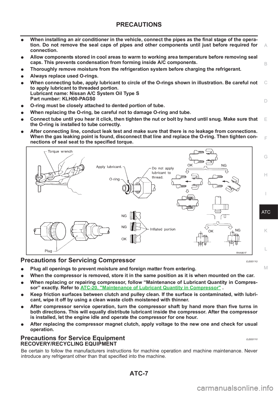
●When connecting tube, apply lubricant to circle of the O-rings shown in illustration. Be careful not
to apply lubricant to threaded portion.
Lubricant name: Nissan A/C System Oil Type S
Part number: KLH00-PAGS0
●O-ring must be closely attached to dented portion of tube.
●When replacing the O-ring, be careful not to damage O-ring and tube.
●Connect tube until you hear it click, then tighten the nut or bolt by hand until snug. Make sure that
the O-ring is installed to tube correctly.
●After connecting line, conduct leak test and make sure that there is no leakage from connections.
When the gas leaking point is found, disconnect that line and replace the O-ring. Then tighten con-
nections of seal seat to the specified torque.
Precautions for Servicing CompressorEJS001YU
●Plug all openings to prevent moisture and foreign matter from entering.
●When the compressor is removed, store it in the same position as it is when mounted on the car.
●When replacing or repairing compressor, follow “Maintenance of Lubricant Quantity in Compres-
sor” exactly. Refer to ATC-20, "
Maintenance of Lubricant Quantity in Compressor" .
●Keep friction surfaces between clutch and pulley clean. If the surface is contaminated, with lubri-
cant, wipe it off by using a clean waste cloth moistened with thinner.
●After compressor service operation, turn the compressor shaft by hand more than five turns in
both directions. This will equally distribute lubricant inside the compressor. After the compressor
is installed, let the engine idle and operate the compressor for one hour.
●After replacing the compressor magnet clutch, apply voltage to the new one and check for usual
operation.
Precautions for Service EquipmentEJS001YV
RECOVERY/RECYCLING EQUIPMENT
Be certain to follow the manufacturers instructions for machine operation and machine maintenance. Never
introduce any refrigerant other than that specified into the machine.
RHA861F
Page 2117 of 3189
REFRIGERANT LINES
ATC-137
C
D
E
F
G
H
I
K
L
MA
B
AT C
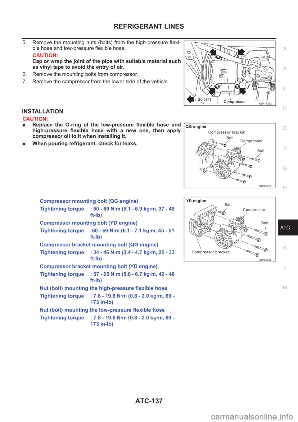
5. Remove the mounting nuts (bolts) from the high-pressure flexi-
ble hose and low-pressure flexible hose.
CAUTION:
Cap or wrap the joint of the pipe with suitable material such
as vinyl tape to avoid the entry of air.
6. Remove the mounting bolts from compressor.
7. Remove the compressor from the lower side of the vehicle.
INSTALLATION
CAUTION:
●Replace the O-ring of the low-pressure flexible hose and
high-pressure flexible hose with a new one, then apply
compressor oil to it when installing it.
●When pouring refrigerant, check for leaks.
RJIA1730E
RJIA0837E
Compressor mounting bolt (QG engine)
Tightening torque : 50 - 60 N·m (5.1 - 6.9 kg·m, 37 - 49
ft-lb)
Compressor mounting bolt (YD engine)
Tightening torque :60 - 69 N·m (6.1 - 7.1 kg·m, 45 - 51
ft-lb)
Compressor bracket mounting bolt (QG engine)
Tightening torque : 34 - 46 N·m (3.4 - 4.7 kg·m, 25 - 33
ft-lb)
Compressor bracket mounting bolt (YD engine)
Tightening torque : 57 - 65 N·m (5.8 - 6.7 kg·m, 42 - 48
ft-lb)
Nut (bolt) mounting the high-pressure flexible hose
Tightening torque : 7.8 - 19.6 N·m (0.8 - 2.0 kg·m, 69 -
173 in-lb)
Nut (bolt) mounting the low-pressure flexible hose
Tightening torque : 7.8 - 19.6 N·m (0.8 - 2.0 kg·m, 69 -
173 in-lb)
RJIA0838E
Page 2120 of 3189
ATC-140
REFRIGERANT LINES
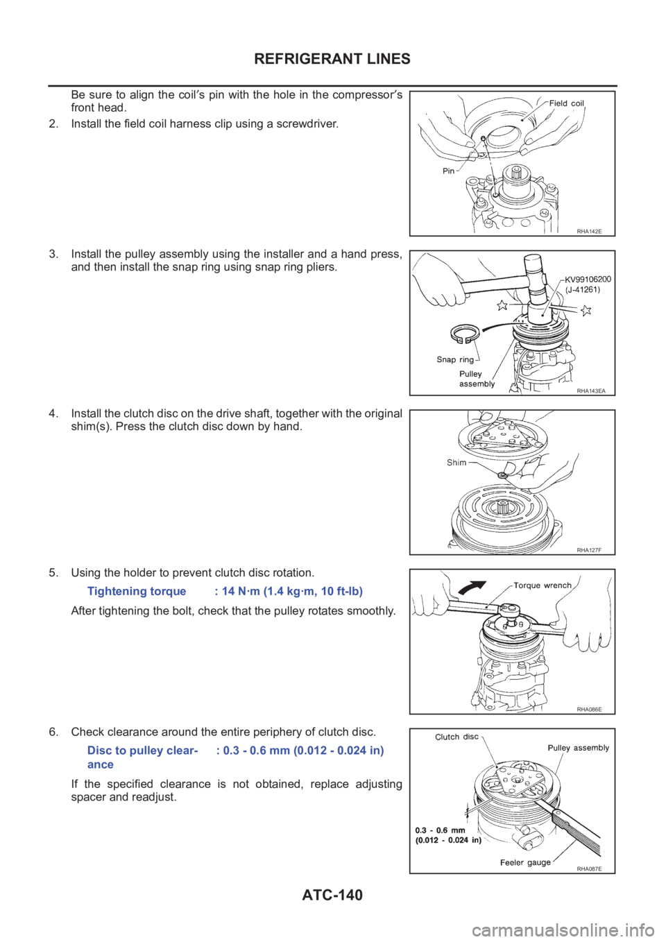
Be sure to align the coil′s pin with the hole in the compressor′s
front head.
2. Install the field coil harness clip using a screwdriver.
3. Install the pulley assembly using the installer and a hand press,
and then install the snap ring using snap ring pliers.
4. Install the clutch disc on the drive shaft, together with the original
shim(s). Press the clutch disc down by hand.
5. Using the holder to prevent clutch disc rotation.
After tightening the bolt, check that the pulley rotates smoothly.
6. Check clearance around the entire periphery of clutch disc.
If the specified clearance is not obtained, replace adjusting
spacer and readjust.
RHA142E
RHA143EA
RHA127F
Tightening torque : 14 N·m (1.4 kg·m, 10 ft-lb)
RHA086E
Disc to pulley clear-
ance: 0.3 - 0.6 mm (0.012 - 0.024 in)
RHA087E
Page 2121 of 3189
REFRIGERANT LINES
ATC-141
C
D
E
F
G
H
I
K
L
MA
B
AT C
Break-In Operation
When replacing compressor clutch assembly, always carry out the break-in operation. This is done by engag-
ing and disengaging the clutch about thirty times. Break-in operation raises the level of transmitted torque.
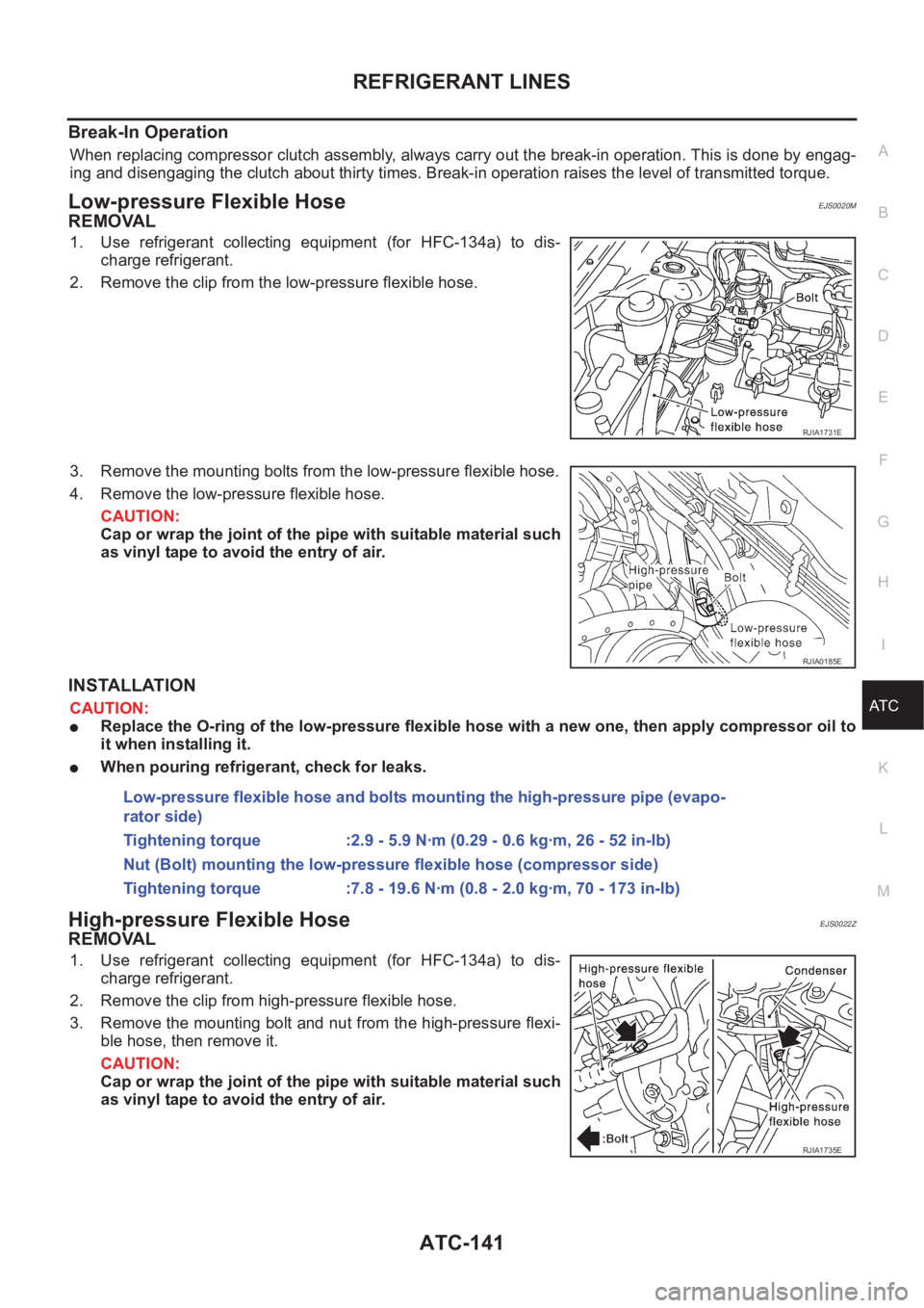
Low-pressure Flexible HoseEJS0020M
REMOVAL
1. Use refrigerant collecting equipment (for HFC-134a) to dis-
charge refrigerant.
2. Remove the clip from the low-pressure flexible hose.
3. Remove the mounting bolts from the low-pressure flexible hose.
4. Remove the low-pressure flexible hose.
CAUTION:
Cap or wrap the joint of the pipe with suitable material such
as vinyl tape to avoid the entry of air.
INSTALLATION
CAUTION:
●Replace the O-ring of the low-pressure flexible hose with a new one, then apply compressor oil to
it when installing it.
●When pouring refrigerant, check for leaks.
High-pressure Flexible HoseEJS0022Z
REMOVAL
1. Use refrigerant collecting equipment (for HFC-134a) to dis-
charge refrigerant.
2. Remove the clip from high-pressure flexible hose.
3. Remove the mounting bolt and nut from the high-pressure flexi-
ble hose, then remove it.
CAUTION:
Cap or wrap the joint of the pipe with suitable material such
as vinyl tape to avoid the entry of air.
RJIA1731E
RJIA0185E
Low-pressure flexible hose and bolts mounting the high-pressure pipe (evapo-
rator side)
Tightening torque :2.9 - 5.9 N·m (0.29 - 0.6 kg·m, 26 - 52 in-lb)
Nut (Bolt) mounting the low-pressure flexible hose (compressor side)
Tightening torque :7.8 - 19.6 N·m (0.8 - 2.0 kg·m, 70 - 173 in-lb)
RJIA1735E
Page 2122 of 3189
ATC-142
REFRIGERANT LINES
INSTALLATION
CAUTION:
●Replace the O-ring of the high-pressure flexible hose with a new one, then apply compressor oil to
it when installing it.
●When pouring refrigerant, check for leaks.
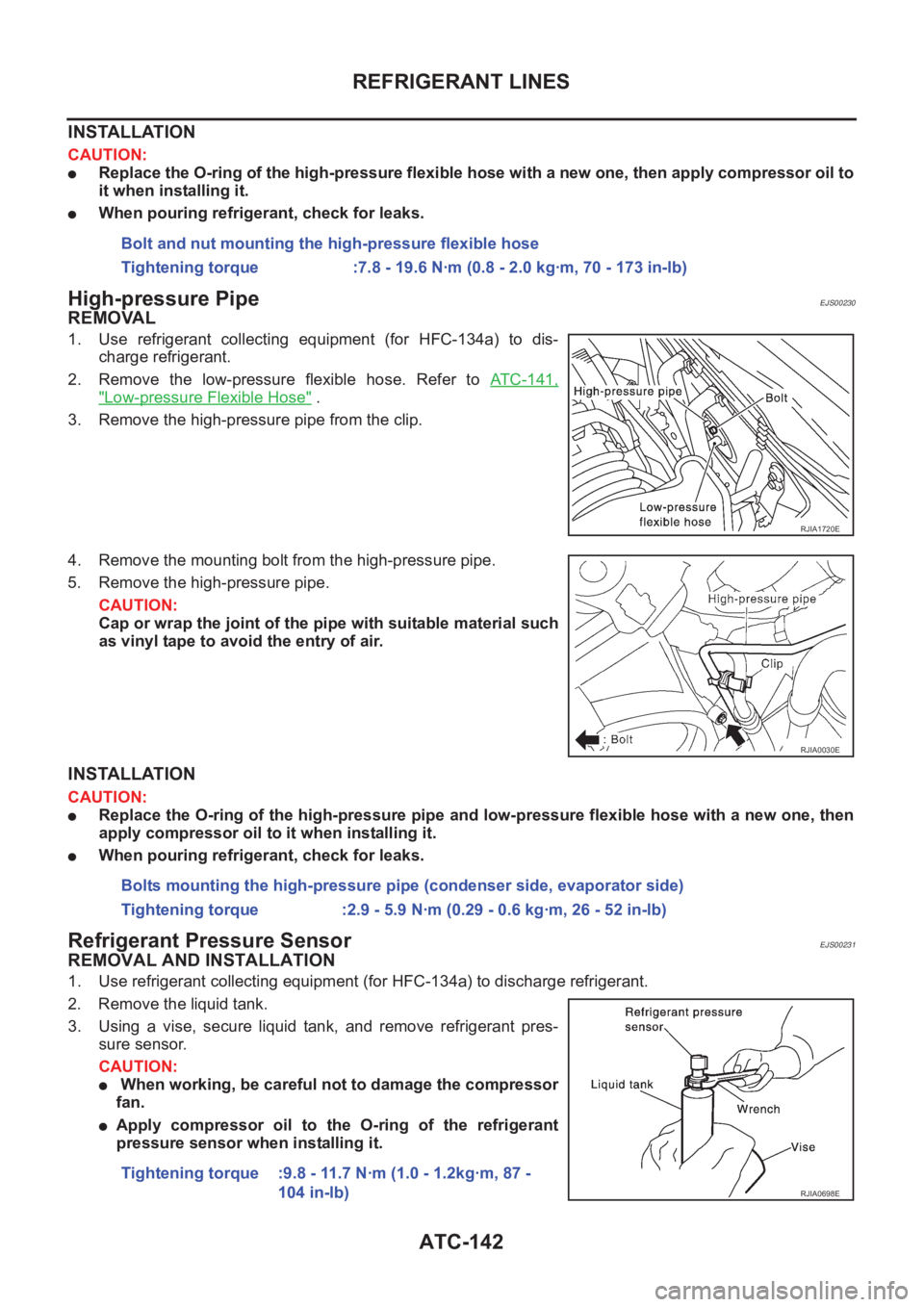
High-pressure PipeEJS00230
REMOVAL
1. Use refrigerant collecting equipment (for HFC-134a) to dis-
charge refrigerant.
2. Remove the low-pressure flexible hose. Refer to ATC-141,
"Low-pressure Flexible Hose" .
3. Remove the high-pressure pipe from the clip.
4. Remove the mounting bolt from the high-pressure pipe.
5. Remove the high-pressure pipe.
CAUTION:
Cap or wrap the joint of the pipe with suitable material such
as vinyl tape to avoid the entry of air.
INSTALLATION
CAUTION:
●Replace the O-ring of the high-pressure pipe and low-pressure flexible hose with a new one, then
apply compressor oil to it when installing it.
●When pouring refrigerant, check for leaks.
Refrigerant Pressure SensorEJS00231
REMOVAL AND INSTALLATION
1. Use refrigerant collecting equipment (for HFC-134a) to discharge refrigerant.
2. Remove the liquid tank.
3. Using a vise, secure liquid tank, and remove refrigerant pres-
sure sensor.
CAUTION:
● When working, be careful not to damage the compressor
fan.
●Apply compressor oil to the O-ring of the refrigerant
pressure sensor when installing it.Bolt and nut mounting the high-pressure flexible hose
Tightening torque :7.8 - 19.6 N·m (0.8 - 2.0 kg·m, 70 - 173 in-lb)
RJIA1720E
RJIA0030E
Bolts mounting the high-pressure pipe (condenser side, evaporator side)
Tightening torque :2.9 - 5.9 N·m (0.29 - 0.6 kg·m, 26 - 52 in-lb)
Tightening torque :9.8 - 11.7 N·m (1.0 - 1.2kg·m, 87 -
104 in-lb)
RJIA0698E