Page 3009 of 3189

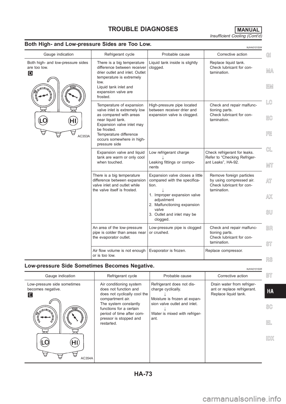
Both High- and Low-pressure Sides are Too Low.NJHA0151S04
Gauge indication Refrigerant cycle Probable cause Corrective action
Both high- and low-pressure sides
are too low.
AC353A
There is a big temperature
difference between receiver
drier outlet and inlet. Outlet
temperature is extremely
low.
Liquid tank inlet and
expansion valve are
frosted.Liquid tank inside is slightly
clogged.Replace liquid tank.
Check lubricant for con-
tamination.
Temperature of expansion
valve inlet is extremely low
as compared with areas
near liquid tank.
Expansion valve inlet may
be frosted.
Temperature difference
occurs somewhere in high-
pressure sideHigh-pressure pipe located
between receiver drier and
expansion valve is clogged.Check and repair malfunc-
tioning parts.
Check lubricant for con-
tamination.
Expansion valve and liquid
tank are warm or only cool
when touched.Low refrigerant charge
"
Leaking fittings or compo-
nentsCheck refrigerant for leaks.
Refer to “Checking Refriger-
ant Leaks”, HA-92.
There is a big temperature
difference between expansion
valve inlet and outlet while
the valve itself is frosted.Expansion valve closes a little
compared with the specifica-
tion.
"
1. Improper expansion valve
adjustment
2. Malfunctioning expansion
valve
3. Outlet and inlet may be
clogged.Remove foreign particles
by using compressed air.
Check lubricant for con-
tamination.
An area of the low-pressure
pipe is colder than areas near
the evaporator outlet.Low-pressure pipe is clogged
or crushed.Check and repair malfunc-
tioning parts.
Check lubricant for con-
tamination.
Air flow volume is not enough
or is too low.Evaporator is frozen. Replace compressor.
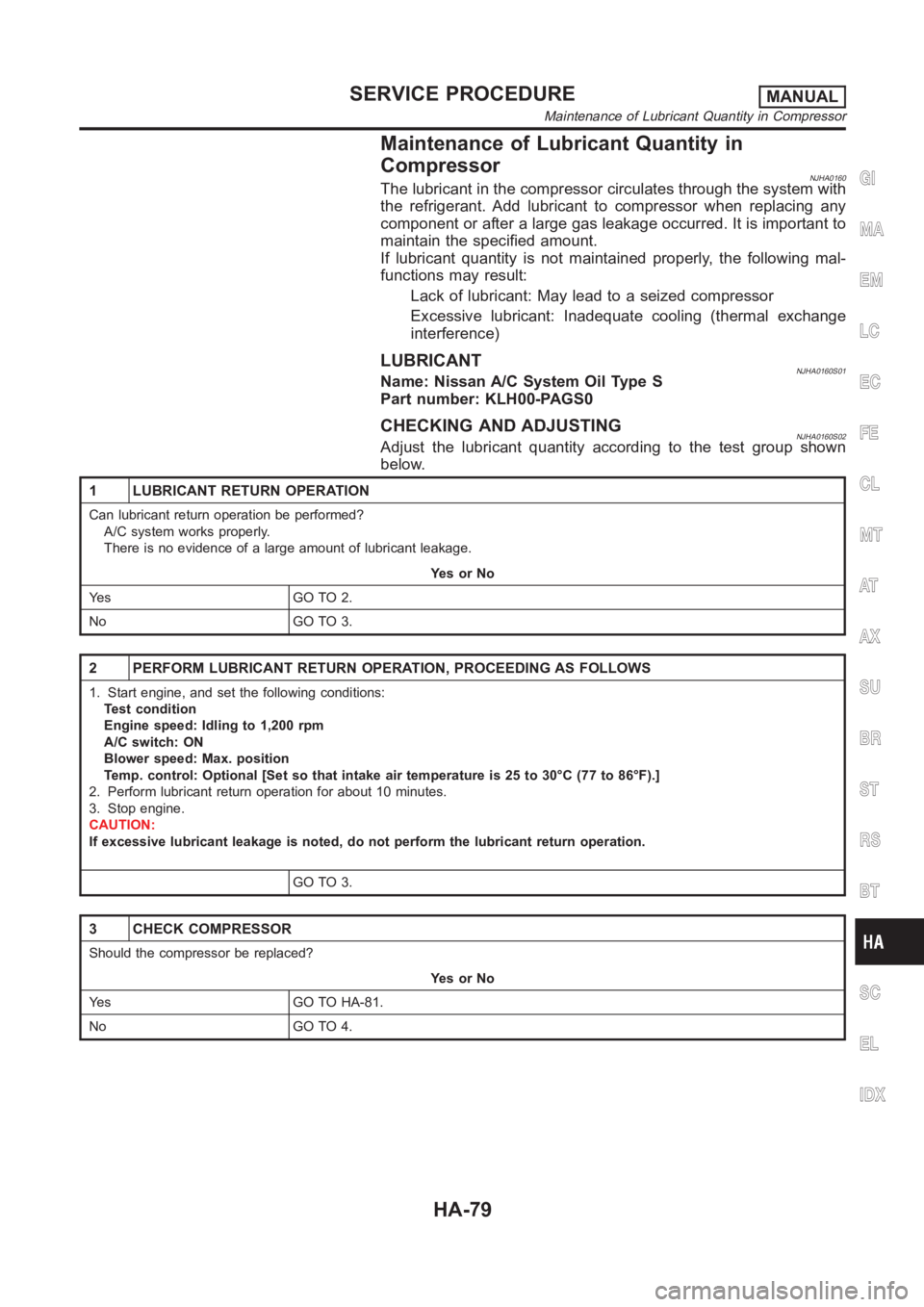
Low-pressure Side Sometimes Becomes Negative.NJHA0151S05
Gauge indication Refrigerant cycle Probable cause Corrective action
Low-pressure side sometimes
becomes negative.
AC354A
Air conditioning system
does not function and
does not cyclically cool the
compartment air.
The system constantly
functions for a certain
period of time after com-
pressor is stopped and
restarted.Refrigerant does not dis-
charge cyclically.
"
Moisture is frozen at expan-
sion valve outlet and inlet.
"
Water is mixed with refriger-
ant.Drain water from refriger-
ant or replace refrigerant.
Replace liquid tank.
GI
MA
EM
LC
EC
FE
CL
MT
AT
AX
SU
BR
ST
RS
BT
SC
EL
IDX
TROUBLE DIAGNOSESMANUAL
Insufficient Cooling (Cont’d)
HA-73
Page 3015 of 3189

Maintenance of Lubricant Quantity in
Compressor
NJHA0160The lubricant in the compressor circulates through the system with
the refrigerant. Add lubricant to compressor when replacing any
component or after a large gas leakage occurred. It is important to
maintain the specified amount.
If lubricant quantity is not maintained properly, the following mal-
functions may result:
Lack of lubricant: May lead to a seized compressor
Excessive lubricant: Inadequate cooling (thermal exchange
interference)
LUBRICANTNJHA0160S01Name: Nissan A/C System Oil Type S
Part number: KLH00-PAGS0
CHECKING AND ADJUSTINGNJHA0160S02Adjust the lubricant quantity according to the test group shown
below.
1 LUBRICANT RETURN OPERATION
Can lubricant return operation be performed?
A/C system works properly.
There is no evidence of a large amount of lubricant leakage.
YesorNo
Ye s G O T O 2 .
No GO TO 3.
2 PERFORM LUBRICANT RETURN OPERATION, PROCEEDING AS FOLLOWS
1. Start engine, and set the following conditions:
Test condition
Engine speed: Idling to 1,200 rpm
A/C switch: ON
Blower speed: Max. position
Temp. control: Optional [Set so that intake air temperature is 25 to 30°C (77 to 86°F).]
2. Perform lubricant return operation for about 10 minutes.
3. Stop engine.
CAUTION:
If excessive lubricant leakage is noted, do not perform the lubricant return operation.
GO TO 3.
3 CHECK COMPRESSOR
Should the compressor be replaced?
YesorNo
Yes GO TO HA-81.
No GO TO 4.
GI
MA
EM
LC
EC
FE
CL
MT
AT
AX
SU
BR
ST
RS
BT
SC
EL
IDX
SERVICE PROCEDUREMANUAL
Maintenance of Lubricant Quantity in Compressor
HA-79
Page 3030 of 3189

5. If a leak detector detects a leak, verify at least once by blow-
ing compressed air into area of suspected leak, then repeat
check as outlined above.
6. Do not stop when one leak is found. Continue to check for
additional leaks at all system components.
If no leaks are found, perform steps 7 - 10.
7. Start engine.
8. Set the heater A/C control as follows:
1) A/C switch ON.
2) Face mode
3) Recirculation position
4) Max cold temperature
5) Fan speed high
9. Run engine at 1,500 rpm for at least 2 minutes.
10. Turn engine off and perform leak check again following steps
4 through 6 above.
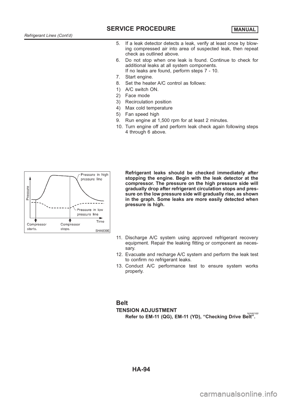
SHA839E
Refrigerant leaks should be checked immediately after
stopping the engine. Begin with the leak detector at the
compressor. The pressure on the high pressure side will
gradually drop after refrigerant circulation stops and pres-
sure on the low pressure side will gradually rise, as shown
in the graph. Some leaks are more easily detected when
pressure is high.
11. Discharge A/C system using approved refrigerant recovery
equipment. Repair the leaking fitting or component as neces-
sary.
12. Evacuate and recharge A/C system and perform the leak test
to confirm no refrigerant leaks.
13. Conduct A/C performance test to ensure system works
properly.
Belt
TENSION ADJUSTMENTNJHA0169Refer to EM-11 (QG), EM-11 (YD), “Checking Drive Belt”.
SERVICE PROCEDUREMANUAL
Refrigerant Lines (Cont’d)
HA-94
Page 3115 of 3189
![NISSAN ALMERA N16 2003 Electronic Repair Manual Fig. 2 INITIAL CHARGING CURRENT SETTING (Slow charge)
CON-
VERTED
SPECIFIC
GRAVITYBATTERY TYPE
28B19R(L)
34B19R(L)
46B24R(L)
55B24R(L)
50D23R(L)
55D23R(L)
025 [YUASA type code]
027 [YUASA type code]
6 NISSAN ALMERA N16 2003 Electronic Repair Manual Fig. 2 INITIAL CHARGING CURRENT SETTING (Slow charge)
CON-
VERTED
SPECIFIC
GRAVITYBATTERY TYPE
28B19R(L)
34B19R(L)
46B24R(L)
55B24R(L)
50D23R(L)
55D23R(L)
025 [YUASA type code]
027 [YUASA type code]
6](/manual-img/5/57350/w960_57350-3114.png)
Fig. 2 INITIAL CHARGING CURRENT SETTING (Slow charge)
CON-
VERTED
SPECIFIC
GRAVITYBATTERY TYPE
28B19R(L)
34B19R(L)
46B24R(L)
55B24R(L)
50D23R(L)
55D23R(L)
025 [YUASA type code]
027 [YUASA type code]
65D26R(L)
80D26R(L)
063 [YUASA type code]
067 [YUASA type code]
096 [YUASA type code]
75D31R(L)
95D31R(L)
115D31R(L)
110D26R(L)
95E41R(L)
065 [YUASA type code]
075 [YUASA type code]
096L [YUASA type code]
010S [YUASA type code]
130E41R(L)
Below 1.100 4.0 (A) 5.0 (A) 7.0 (A) 8.0 (A)8.5
(A)9.0
(A)10.0 (A) 11.0 (A)14.0
(A)
Check battery type and determine the specified current using the table shown above.
After starting charging, adjustment of charging current is not necessary.
Fig. 3 ADDITIONAL CHARGE (Slow charge)
SEL757W
*: SC-7
CAUTION:
Set charging current to value specified in Fig. 2. If charger is not capableof producing specified
current value, set its charging current as close to that value as possible.
Keep battery away from open flame while it is being charged.
When connecting charger, connect leads first, then turn on charger. Do notturn on charger first,
as this may cause a spark.
If battery temperature rises above 60°C (140°F), stop charging. Always charge battery when its
temperature is below 60°C (140°F).
GI
MA
EM
LC
EC
FE
CL
MT
AT
AX
SU
BR
ST
RS
BT
HA
EL
IDX
BATTERY
Battery Test and Charging Chart (Cont’d)
SC-9
Page 3118 of 3189
![NISSAN ALMERA N16 2003 Electronic Repair Manual Fig. 6 INITIAL CHARGING CURRENT SETTING AND CHARGING TIME (Quick charge)
BATTERY
TYPE
28B19R(L)
34B19R(L)
46B24R(L)
55B24R(L)
50D23R(L)
55D23R(L)
65D26R(L)
80D26R(L)
025 [YUASA type code]
027 [YUASA t NISSAN ALMERA N16 2003 Electronic Repair Manual Fig. 6 INITIAL CHARGING CURRENT SETTING AND CHARGING TIME (Quick charge)
BATTERY
TYPE
28B19R(L)
34B19R(L)
46B24R(L)
55B24R(L)
50D23R(L)
55D23R(L)
65D26R(L)
80D26R(L)
025 [YUASA type code]
027 [YUASA t](/manual-img/5/57350/w960_57350-3117.png)
Fig. 6 INITIAL CHARGING CURRENT SETTING AND CHARGING TIME (Quick charge)
BATTERY
TYPE
28B19R(L)
34B19R(L)
46B24R(L)
55B24R(L)
50D23R(L)
55D23R(L)
65D26R(L)
80D26R(L)
025 [YUASA type code]
027 [YUASA type code]
063 [YUASA type code]
067 [YUASA type code]
096 [YUASA type code]
065 [YUASA type code]
075 [YUASA type code]
096L [YUASA type code]
010S [YUASA type code]
75D31R(L)
95D31R(L)
115D31R(L)
110D26R(L)
95E41R(L)
130E41R(L)
CURRENT
[A]10 (A) 15 (A) 20 (A) 25 (A) 30 (A)40
(A)
CONVERTED SPECIFIC GRAVITY
1.100 -
1.1302.5 hours
1.130 -
1.1602.0 hours
1.160 -
1.1901.5 hours
1.190 -
1.2201.0 hours
Above
1.2200.75 hours (45 min.)
Check battery type and determine the specified current using the table shown above.
After starting charging, adjustment of charging current is not necessary.
CAUTION:
Do not use quick charge method on a battery whose specific gravity is less than 1.100.
Set initial charging current to value specified in Fig. 6. If charger is notcapable of producing
specified current value, set its charging current as close to that value aspossible.
Keep battery away from open flame while it is being charged.
When connecting charger, connect leads first, then turn on charger. Do notturn on charger first,
as this may cause a spark.
Be careful of a rise in battery temperature because a large current flow is required during quick-
charge operation.
If battery temperature rises above 60°C (140°F), stop charging. Always charge battery when its
temperature is below 60°C (140°F).
Do not exceed the charging time specified in Fig. 6, because charging battery over the charging
time can cause deterioration of the battery.
BATTERY
Battery Test and Charging Chart (Cont’d)
SC-12
Page 3127 of 3189
MKIA0009E
1. Bushing
2. Gear case
3. Magnetic switch assembly
4. Stopper clip
5. Pinion stopper6. Bushing
7. Pinion assembly
8. Shift lever
9. Armature
10. Packing11 . Yo k e
12. Brush holder
13. Rear cover
14. Bushing
15. Cap
GI
MA
EM
LC
EC
FE
CL
MT
AT
AX
SU
BR
ST
RS
BT
HA
EL
IDX
STARTING SYSTEM
Construction (Cont’d)
SC-21
Page 3128 of 3189
MKIA0010E
1. Gear case
2. Bushing
3. Magnetic switch assembly
4. Stopper clip
5. Pinion stopper6. Bushing
7. Pinion assembly
8. Shift lever
9. Armature
10. Packing11 . Yo k e
12. Brush holder
13. Bushing
14. Rear cover
SEL909TA
Removal and InstallationNJSC0007REMOVALNJSC0007S011. Remove intake air duct and air cleaner assembly.
2. Disconnect starter harness.
3. Remove starter bolts (two).
4. Remove starter.
MEL137L
INSTALLATIONNJSC0007S02To install, reverse the removal procedure.
STARTING SYSTEM
Construction (Cont’d)
SC-22
Page 3132 of 3189
SEL026Z
PINION PROTRUSION LENGTH ADJUSTMENTNJSC0020S01Clearance (QG engine models)NJSC0020S0101With pinion driven out by magnetic switch, push pinion back to
remove slack and measure clearance “�” between the front edge
of the pinion and the pinion stopper.
Clearance “�”:
Refer to SDS (SC-37).
MEL140L
Movement (YD engine models)NJSC0020S0102Compare movement “�” in height of pinion when it is pushed out
with magnetic switch energized and when it is pulled out by hand
until it touches stopper.
Movement “�”:
Refer to SDS (SC-37).
SEL633BA
Not in the specified value ... Adjust by adjusting plate.
STARTING SYSTEM
Assembly (Cont’d)
SC-26