2003 NISSAN ALMERA N16 stop start
[x] Cancel search: stop startPage 2127 of 3189
REFRIGERANT LINES
ATC-147
C
D
E
F
G
H
I
K
L
MA
B
AT C
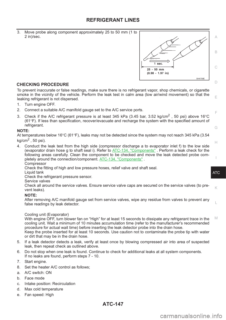
3. Move probe along component approximately 25 to 50 mm (1 to
2 in)/sec.
CHECKING PROCEDURE
To prevent inaccurate or false readings, make sure there is no refrigerant vapor, shop chemicals, or cigarette
smoke in the vicinity of the vehicle. Perform the leak test in calm area (low air/wind movement) so that the
leaking refrigerant is not dispersed.
1. Turn engine OFF.
2. Connect a suitable A/C manifold gauge set to the A/C service ports.
3. Check if the A/C refrigerant pressure is at least 345 kPa (3.45 bar, 3.52 kg/cm
2 , 50 psi) above 16°C
(61°F). If less than specification, recover/evacuate and recharge the system with the specified amount of
refrigerant.
NOTE:
At temperatures below 16°C (61°F), leaks may not be detected since the system may not reach 345 kPa (3.54
kg/cm
2 , 50 psi).
4. Conduct the leak test from the high side (compressor discharge a to evaporator inlet f) to the low side
(evaporator drain hose g to shaft seal i). Refer to AT C - 1 3 4 , "
Components" . Perform a leak check for the
following areas carefully. Clean the component to be checked and move the leak detected probe com-
pletely around the connection/component. ATC-134, "
Components" .
Compressor
Check the fitting of high and low pressure hoses, relief valve and shaft seal.
Liquid tank
Check the refrigerant pressure sensor.
Service valves
Check all around the service valves. Ensure service valve caps are secured on the service valves (to pre-
vent leaks).
NOTE:
After removing A/C manifold gauge set from service valves, wipe any residue from valves to prevent any
false readings by leak detector.
Cooling unit (Evaporator)
With engine OFF, turn blower fan on “High” for at least 15 seconds to dissipate any refrigerant trace in the
cooling unit. Wait a minimum of 10 minutes accumulation time (refer to the manufacturer′s recommended
procedure for actual wait time) before inserting the leak detector probe into the drain hose.
Keep the probe inserted for at least 10 seconds. Use caution not to contaminate the probe tip with water
or dirt that may be in the drain hose.
5. If a leak detector detects a leak, verify at least once by blowing compressed air into area of suspected
leak, then repeat check as outlined above.
6. Do not stop when one leak is found. Continue to check for additional leaks at all system components.
If no leaks are found, perform steps 7 - 10.
7. Start engine.
8. Set the heater A/C control as follows;
a. A/C switch: ON
b. Face mode
c. Intake position: Recirculation
d. Max cold temperature
e. Fan speed: High
SHA708E
Page 2204 of 3189
SBR002A
SBR365AA
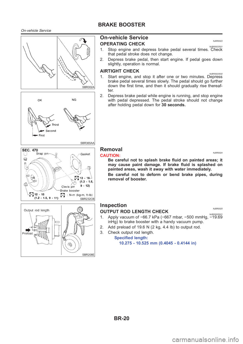
On-vehicle ServiceNJBR0023OPERATING CHECKNJBR0023S011. Stop engine and depress brake pedal several times. Check
that pedal stroke does not change.
2. Depress brake pedal, then start engine. If pedal goes down
slightly, operation is normal.
AIRTIGHT CHECKNJBR0023S021. Start engine, and stop it after one or two minutes. Depress
brake pedal several times slowly. The pedal should go further
down the first time, and then it should gradually rise thereaf-
ter.
2. Depress brake pedal while engine is running, and stop engine
with pedal depressed. The pedal stroke should not change
after holding pedal down for30 seconds.
SBR232CB
RemovalNJBR0024CAUTION:
Be careful not to splash brake fluid on painted areas; it
may cause paint damage. If brake fluid is splashed on
painted areas, wash it away with water immediately.
Be careful not to deform or bend brake pipes, during
removal of booster.
SBR208E
InspectionNJBR0025OUTPUT ROD LENGTH CHECKNJBR0025S011. Apply vacuum of −66.7 kPa (−667 mbar, −500 mmHg, −19.69
inHg) to brake booster with a handy vacuum pump.
2. Add preload of 19.6 N (2 kg, 4.4 lb) to output rod.
3. Check output rod length.
Specified length:
10.275 - 10.525 mm (0.4045 - 0.4144 in)
BRAKE BOOSTER
On-vehicle Service
BR-20
Page 2238 of 3189
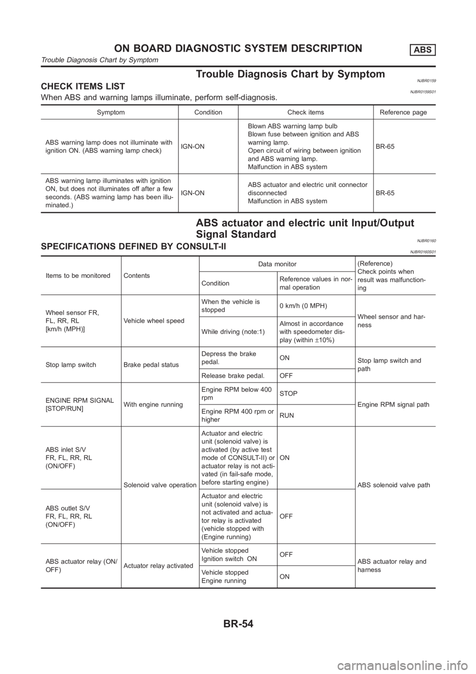
Trouble Diagnosis Chart by SymptomNJBR0159CHECK ITEMS LISTNJBR0159S01When ABS and warning lamps illuminate, perform self-diagnosis.
Symptom Condition Check items Reference page
ABS warning lamp does not illuminate with
ignition ON. (ABS warning lamp check)IGN-ONBlown ABS warning lamp bulb
Blown fuse between ignition and ABS
warning lamp.
Open circuit of wiring between ignition
and ABS warning lamp.
Malfunction in ABS systemBR-65
ABS warning lamp illuminates with ignition
ON, but does not illuminates off after a few
seconds. (ABS warning lamp has been illu-
minated.)IGN-ONABS actuator and electric unit connector
disconnected
Malfunction in ABS systemBR-65
ABS actuator and electric unit Input/Output
Signal Standard
NJBR0160SPECIFICATIONS DEFINED BY CONSULT-IINJBR0160S01
Items to be monitored ContentsData monitor(Reference)
Check points when
result was malfunction-
ing ConditionReference values in nor-
mal operation
Wheel sensor FR,
FL, RR, RL
[km/h (MPH)]Vehicle wheel speedWhen the vehicle is
stopped0 km/h (0 MPH)
Wheel sensor and har-
ness
While driving (note:1)Almost in accordance
with speedometer dis-
play (within±10%)
Stop lamp switch Brake pedal statusDepress the brake
pedal.ON
Stop lamp switch and
path
Release brake pedal. OFF
ENGINE RPM SIGNAL
[STOP/RUN]With engine runningEngine RPM below 400
rpmSTOP
Engine RPM signal path
Engine RPM 400 rpm or
higherRUN
ABS inlet S/V
FR, FL, RR, RL
(ON/OFF)
Solenoid valve operationActuator and electric
unit (solenoid valve) is
activated (by active test
mode of CONSULT-II) or
actuator relay is not acti-
vated (in fail-safe mode,
before starting engine)ON
ABS solenoid valve path
ABS outlet S/V
FR, FL, RR, RL
(ON/OFF)Actuator and electric
unit (solenoid valve) is
not activated and actua-
tor relay is activated
(vehicle stopped with
(Engine running)OFF
ABS actuator relay (ON/
OFF)Actuator relay activatedVehicle stopped
Ignition switch ONOFF
ABS actuator relay and
harness
Vehicle stopped
Engine runningON
ON BOARD DIAGNOSTIC SYSTEM DESCRIPTIONABS
Trouble Diagnosis Chart by Symptom
BR-54
Page 2239 of 3189
Items to be monitored ContentsData monitor(Reference)
Check points when
result was malfunction-
ing ConditionReference values in nor-
mal operation
ABS motor relay
(ON/OFF)Motor relay and motor
activated(Ignition switch ON or
engine is running): ABS
inactiveOFF
ABS motor and motor
relay harness
(Ignition switch ON or
engine is running): ABS
activeON
Warning lamp
(ON/OFF)ABS warning lamp ON
condition (Note 2)ABS warning lamp ON ON
ABS warning lamp and
path ABS warning lamp OFF
conditionOFF
POWER VOLTAGE (V)Battery voltage supplied
to control moduleIgnition switch ON Approx. 10 - 16 VControl unit power sup-
ply circuit
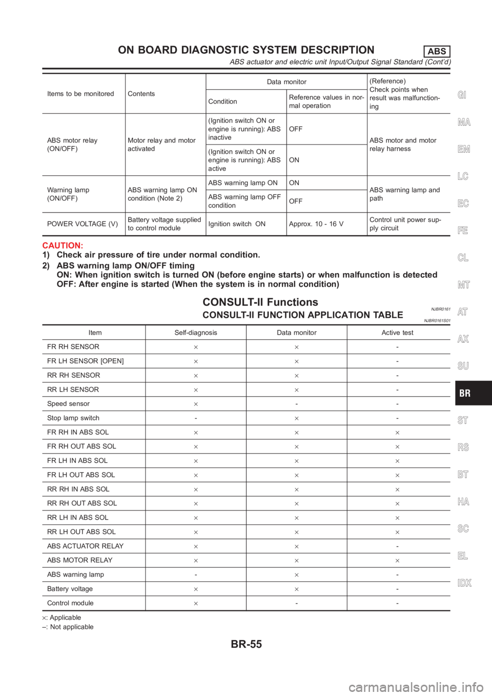
CAUTION:
1) Check air pressure of tire under normal condition.
2) ABS warning lamp ON/OFF timing
ON: When ignition switch is turned ON (before engine starts) or when malfunction is detected
OFF: After engine is started (When the system is in normal condition)
CONSULT-II FunctionsNJBR0161CONSULT-II FUNCTION APPLICATION TABLENJBR0161S01
Item Self-diagnosis Data monitor Active test
FR RH SENSOR××-
FR LH SENSOR [OPEN]××-
RR RH SENSOR××-
RR LH SENSOR××-
Speed sensor×--
Stop lamp switch -×-
FR RH IN ABS SOL×××
FR RH OUT ABS SOL×××
FR LH IN ABS SOL×××
FR LH OUT ABS SOL×××
RR RH IN ABS SOL×××
RR RH OUT ABS SOL×××
RR LH IN ABS SOL×××
RR LH OUT ABS SOL×××
ABS ACTUATOR RELAY××-
ABS MOTOR RELAY×××
ABS warning lamp -×-
Battery voltage××-
Control module×--
×: Applicable
–: Not applicable
GI
MA
EM
LC
EC
FE
CL
MT
AT
AX
SU
ST
RS
BT
HA
SC
EL
IDX
ON BOARD DIAGNOSTIC SYSTEM DESCRIPTIONABS
ABS actuator and electric unit Input/Output Signal Standard (Cont’d)
BR-55
Page 2240 of 3189
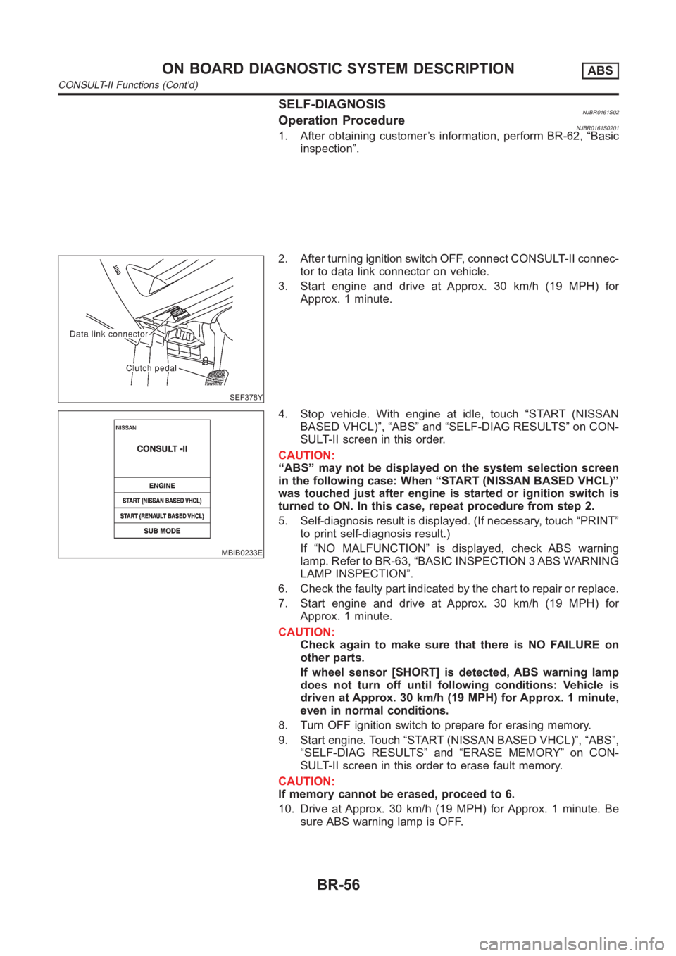
SELF-DIAGNOSISNJBR0161S02Operation ProcedureNJBR0161S02011. After obtaining customer’s information, perform BR-62, “Basic
inspection”.
SEF378Y
2. After turning ignition switch OFF, connect CONSULT-II connec-
tor to data link connector on vehicle.
3. Start engine and drive at Approx. 30 km/h (19 MPH) for
Approx. 1 minute.
MBIB0233E
4. Stop vehicle. With engine at idle, touch “START (NISSAN
BASED VHCL)”, “ABS” and “SELF-DIAG RESULTS” on CON-
SULT-II screen in this order.
CAUTION:
“ABS” may not be displayed on the system selection screen
in the following case: When “START (NISSAN BASED VHCL)”
was touched just after engine is started or ignition switch is
turned to ON. In this case, repeat procedure from step 2.
5. Self-diagnosis result is displayed. (If necessary, touch “PRINT”
to print self-diagnosis result.)
If “NO MALFUNCTION” is displayed, check ABS warning
lamp. Refer to BR-63, “BASIC INSPECTION 3 ABS WARNING
LAMP INSPECTION”.
6. Check the faulty part indicated by the chart to repair or replace.
7. Start engine and drive at Approx. 30 km/h (19 MPH) for
Approx. 1 minute.
CAUTION:
Check again to make sure that there is NO FAILURE on
other parts.
If wheel sensor [SHORT] is detected, ABS warning lamp
does not turn off until following conditions: Vehicle is
driven at Approx. 30 km/h (19 MPH) for Approx. 1 minute,
even in normal conditions.
8. Turn OFF ignition switch to prepare for erasing memory.
9. Start engine. Touch “START (NISSAN BASED VHCL)”, “ABS”,
“SELF-DIAG RESULTS” and “ERASE MEMORY” on CON-
SULT-II screen in this order to erase fault memory.
CAUTION:
If memory cannot be erased, proceed to 6.
10. Drive at Approx. 30 km/h (19 MPH) for Approx. 1 minute. Be
sure ABS warning lamp is OFF.
ON BOARD DIAGNOSTIC SYSTEM DESCRIPTIONABS
CONSULT-II Functions (Cont’d)
BR-56
Page 2243 of 3189
PBR385C
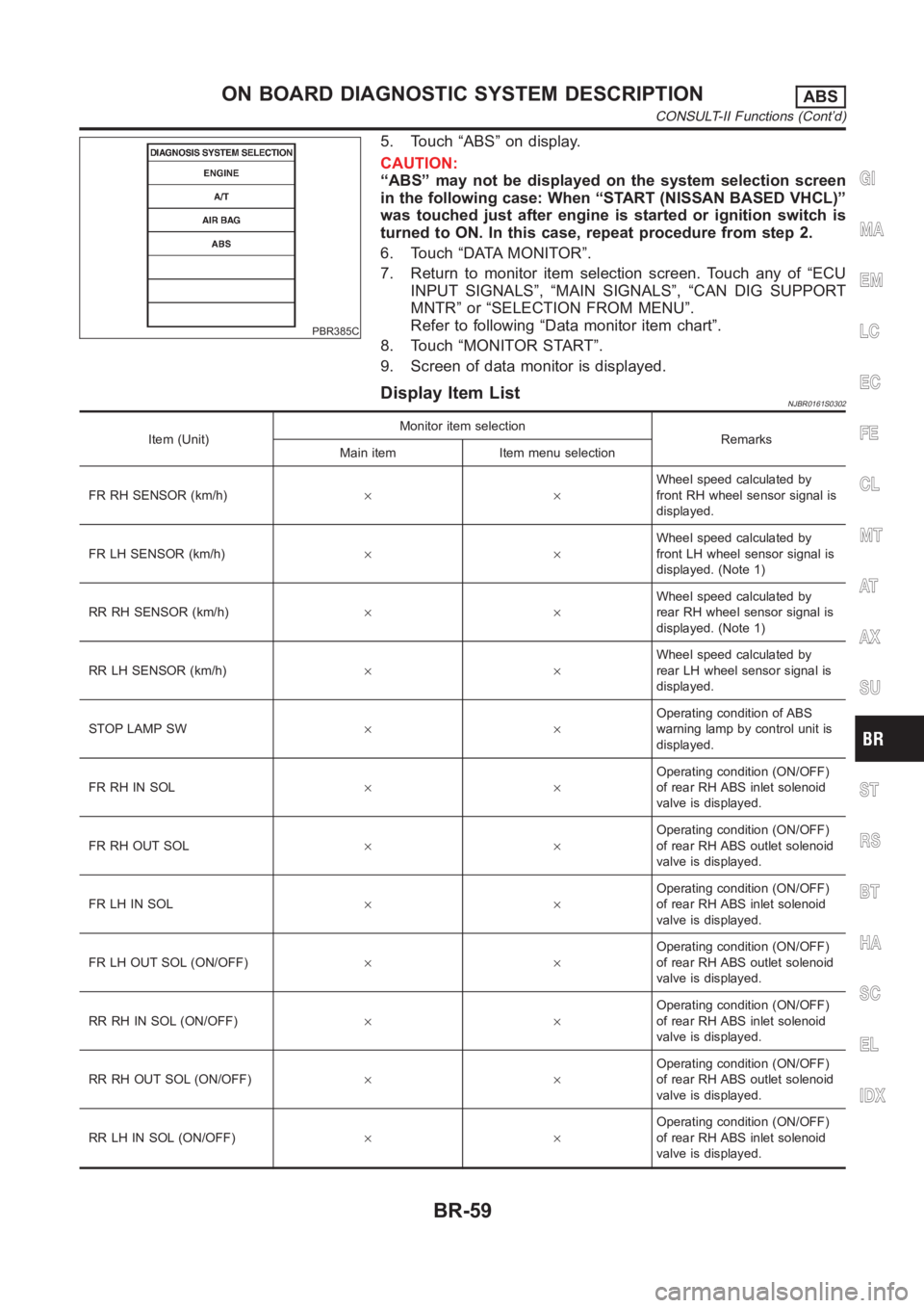
5. Touch “ABS” on display.
CAUTION:
“ABS” may not be displayed on the system selection screen
in the following case: When “START (NISSAN BASED VHCL)”
was touched just after engine is started or ignition switch is
turned to ON. In this case, repeat procedure from step 2.
6. Touch “DATA MONITOR”.
7. Return to monitor item selection screen. Touch any of “ECU
INPUT SIGNALS”, “MAIN SIGNALS”, “CAN DIG SUPPORT
MNTR” or “SELECTION FROM MENU”.
Refer to following “Data monitor item chart”.
8. Touch “MONITOR START”.
9. Screen of data monitor is displayed.
Display Item ListNJBR0161S0302
Item (Unit)Monitor item selection
Remarks
Main item Item menu selection
FR RH SENSOR (km/h)××Wheel speed calculated by
front RH wheel sensor signal is
displayed.
FR LH SENSOR (km/h)××Wheel speed calculated by
front LH wheel sensor signal is
displayed. (Note 1)
RR RH SENSOR (km/h)××Wheel speed calculated by
rear RH wheel sensor signal is
displayed. (Note 1)
RR LH SENSOR (km/h)××Wheel speed calculated by
rear LH wheel sensor signal is
displayed.
STOP LAMP SW××Operating condition of ABS
warning lamp by control unit is
displayed.
FR RH IN SOL××Operating condition (ON/OFF)
of rear RH ABS inlet solenoid
valve is displayed.
FR RH OUT SOL××Operating condition (ON/OFF)
of rear RH ABS outlet solenoid
valve is displayed.
FR LH IN SOL××Operating condition (ON/OFF)
of rear RH ABS inlet solenoid
valve is displayed.
FR LH OUT SOL (ON/OFF)××Operating condition (ON/OFF)
of rear RH ABS outlet solenoid
valve is displayed.
RR RH IN SOL (ON/OFF)××Operating condition (ON/OFF)
of rear RH ABS inlet solenoid
valve is displayed.
RR RH OUT SOL (ON/OFF)××Operating condition (ON/OFF)
of rear RH ABS outlet solenoid
valve is displayed.
RR LH IN SOL (ON/OFF)××Operating condition (ON/OFF)
of rear RH ABS inlet solenoid
valve is displayed.
GI
MA
EM
LC
EC
FE
CL
MT
AT
AX
SU
ST
RS
BT
HA
SC
EL
IDX
ON BOARD DIAGNOSTIC SYSTEM DESCRIPTIONABS
CONSULT-II Functions (Cont’d)
BR-59
Page 2245 of 3189
SFIA0395E
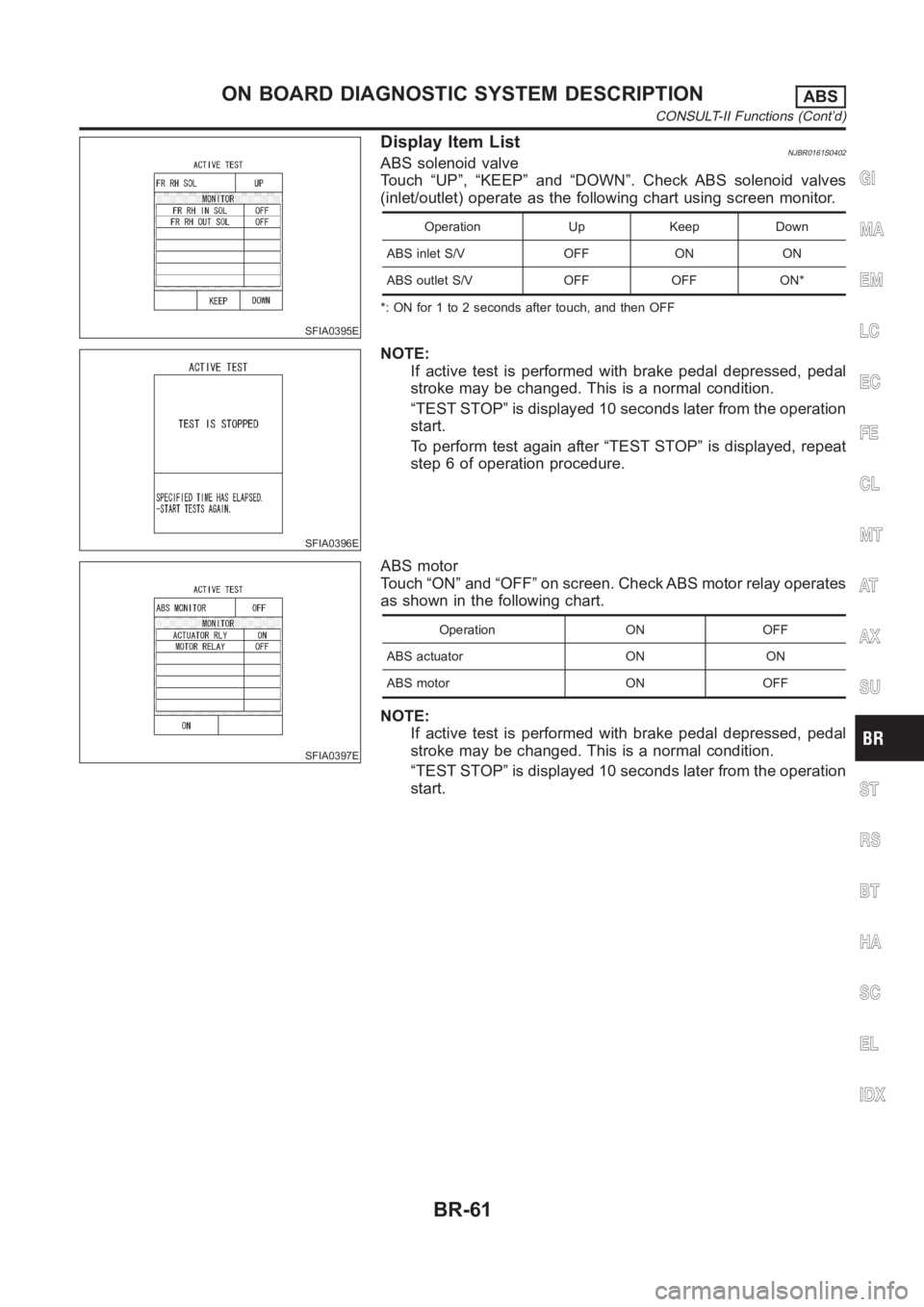
Display Item ListNJBR0161S0402ABS solenoid valve
Touch “UP”, “KEEP” and “DOWN”. Check ABS solenoid valves
(inlet/outlet) operate as the following chart using screen monitor.
Operation Up Keep Down
ABS inlet S/V OFF ON ON
ABS outlet S/V OFF OFF ON*
*: ON for 1 to 2 seconds after touch, and then OFF
SFIA0396E
NOTE:
If active test is performed with brake pedal depressed, pedal
stroke may be changed. This is a normal condition.
“TEST STOP” is displayed 10 seconds later from the operation
start.
To perform test again after “TEST STOP” is displayed, repeat
step 6 of operation procedure.
SFIA0397E
ABS motor
Touch “ON” and “OFF” on screen. Check ABS motor relay operates
as shown in the following chart.
Operation ON OFF
ABS actuator ON ON
ABS motor ON OFF
NOTE:
If active test is performed with brake pedal depressed, pedal
stroke may be changed. This is a normal condition.
“TEST STOP” is displayed 10 seconds later from the operation
start.
GI
MA
EM
LC
EC
FE
CL
MT
AT
AX
SU
ST
RS
BT
HA
SC
EL
IDX
ON BOARD DIAGNOSTIC SYSTEM DESCRIPTIONABS
CONSULT-II Functions (Cont’d)
BR-61
Page 2251 of 3189
5 WHEEL SENSOR INSPECTION
Check the wheel sensor system.
Sensor mounting inspection
Sensor pick-up inspection for iron chips
Sensor rotor inspection (e.g. Number of teeth, damaged teeth)
Sensor connector engagement inspection
Is inspection result OK?
OK Normal
NG Wheel sensor and rotor lines repair
3. Longer Stopping DistanceNJBR0172
1 INSPECTION START
Check that the stopping distance when braking becomes longer only on a snowy or gravel road.
Does the stopping distance when braking become longer only on a snowy or gravel road?
Yes It may be longer than that of vehicle without ABS.
No GO TO 2.
2 PERFORMANCE CHECK
Disconnect the actuator relay box to deactivate the ABS function.
Is the stopping distance still longer?
Yes Brake line air bleeding
Brake line inspection
No GO TO 3.
3 ABS WARNING LAMP INDICATOR INSPECTION
Check that the ABS warning lamp illuminates.
Does the ABS warning lamp illuminate?
Yes Perform the self-diagnosis.
No GO TO 4.
4 WHEEL SENSOR INSPECTION
Check the wheel sensor system.
Sensor mounting inspection
Sensor pick-up inspection for iron chips
Sensor rotor inspection (e.g. Number of teeth, damaged teeth)
Sensor connector engagement inspection
OK or NG
OK Normal
NG Wheel sensor and rotor lines repair
GI
MA
EM
LC
EC
FE
CL
MT
AT
AX
SU
ST
RS
BT
HA
SC
EL
IDX
TROUBLE DIAGNOSES FOR SYMPTOMSABS
2. Unexpected Pedal Action (Cont’d)
BR-67