2003 NISSAN ALMERA N16 stop start
[x] Cancel search: stop startPage 2387 of 3189
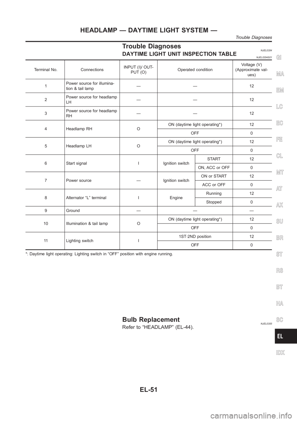
Trouble DiagnosesNJEL0354DAYTIME LIGHT UNIT INSPECTION TABLENJEL0354S01
Terminal No. ConnectionsINPUT (I)/ OUT-
PUT (O)Operated conditionVoltage (V)
(Approximate val-
ues)
1Power source for illumina-
tion & tail lamp——12
2Power source for headlamp
LH——12
3Power source for headlamp
RH——12
4 Headlamp RH OON (daytime light operating*) 12
OFF 0
5 Headlamp LH OON (daytime light operating*) 12
OFF 0
6 Start signal I Ignition switchSTART 12
ON, ACC or OFF 0
7 Power source — Ignition switchON or START 12
ACC or OFF 0
8 Alternator “L” terminal I EngineRunning 12
Stopped 0
9 Ground — — —
10 Illumination & tail lamp OON (daytime light operating*) 12
OFF 0
11 Lighting switch I1ST·2ND position 12
OFF 0
*: Daytime light operating: Lighting switch in “OFF” position with enginerunning.
Bulb ReplacementNJEL0355Refer to “HEADLAMP” (EL-44).
GI
MA
EM
LC
EC
FE
CL
MT
AT
AX
SU
BR
ST
RS
BT
HA
SC
IDX
HEADLAMP — DAYTIME LIGHT SYSTEM —
Trouble Diagnoses
EL-51
Page 2494 of 3189
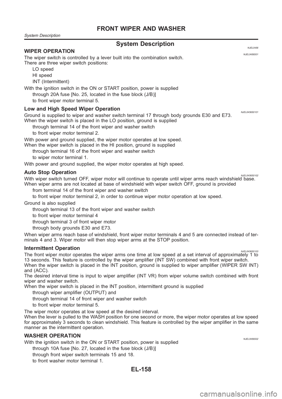
System DescriptionNJEL0456WIPER OPERATIONNJEL0456S01The wiper switch is controlled by a lever built into the combination switch.
There are three wiper switch positions:
LO speed
HI speed
INT (Intermittent)
With the ignition switch in the ON or START position, power is supplied
through 20A fuse [No. 25, located in the fuse block (J/B)]
to front wiper motor terminal 5.
Low and High Speed Wiper OperationNJEL0456S0101Ground is supplied to wiper and washer switch terminal 17 through body grounds E30 and E73.
When the wiper switch is placed in the LO position, ground is supplied
through terminal 14 of the front wiper and washer switch
to front wiper motor terminal 2.
With power and ground supplied, the wiper motor operates at low speed.
When the wiper switch is placed in the HI position, ground is supplied
through terminal 16 of the front wiper and washer switch
to wiper motor terminal 1.
With power and ground supplied, the wiper motor operates at high speed.
Auto Stop OperationNJEL0456S0102With wiper switch turned OFF, wiper motor will continue to operate until wiper arms reach windshield base.
When wiper arms are not located at base of windshield with wiper switch OFF,ground is provided
from terminal 14 of the front wiper and washer switch
to front wiper motor terminal 2, in order to continue wiper motor operationat low speed.
Ground is also supplied
through terminal 13 of the front wiper and washer switch
to front wiper motor terminal 4
through terminal 3 of front wiper motor
through body grounds E30 and E73.
When wiper arms reach base of windshield, front wiper motor terminals 4 and5 are connected instead of ter-
minals 4 and 3. Wiper motor will then stop wiper arms at the STOP position.
Intermittent OperationNJEL0456S0103The front wiper motor operates the wiper arms one time at low speed at a set interval of approximately 1 to
13 seconds. This feature is controlled by the wiper amplifier (INT SW) combined with front wiper switch.
When the wiper switch is placed in the INT position, ground is supplied to wiper amplifier (WIPER SW INT)
and (ACC).
The desired interval time is input to wiper amplifier (INT VR) from wiper volume switch combined with front
wiper and washer switch.
When the wiper switch is placed in the INT position, intermittent ground issupplied
through wiper amplifier (OUTPUT) and
through terminal 14 of front wiper and washer switch
to front wiper motor terminal 5.
The wiper motor operates at low speed at the desired interval.
When the lever is pulled to the WASH position for one second or more, the wiper motor operates at low speed
for approximately 3 seconds to clean windshield. This feature is controlled by the wiper amplifier in the same
manner as the intermittent operation.
WASHER OPERATIONNJEL0456S02With the ignition switch in the ON or START position, power is supplied
through 10A fuse [No. 27, located in the fuse block (J/B)]
through front wiper switch terminals 15 and 18.
to front washer motor terminal 1.
FRONT WIPER AND WASHER
System Description
EL-158
Page 2771 of 3189
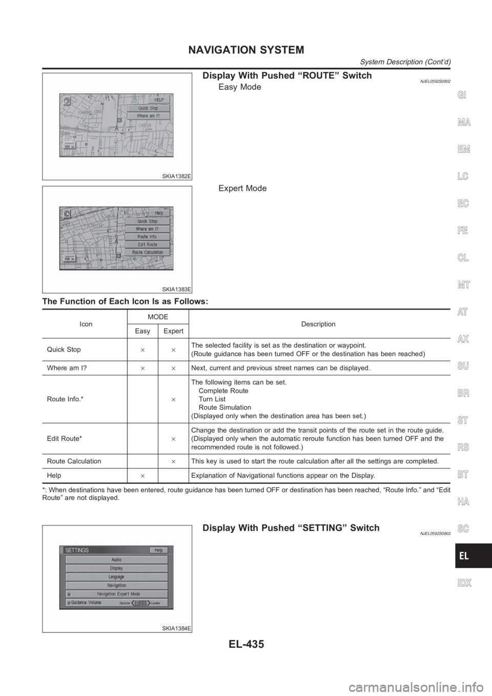
SKIA1382E
Display With Pushed “ROUTE” SwitchNJEL0592S0802Easy Mode
SKIA1383E
Expert Mode
The Function of Each Icon Is as Follows:
IconMODE
Description
Easy Expert
Quick Stop××The selected facility is set as the destination or waypoint.
(Route guidance has been turned OFF or the destination has been reached)
Where am I?××Next, current and previous street names can be displayed.
Route Info.*×The following items can be set.
Complete Route
Turn List
Route Simulation
(Displayed only when the destination area has been set.)
Edit Route*×Change the destination or add the transit points of the route set in the route guide.
(Displayed only when the automatic reroute function has been turned OFF andthe
recommended route is not followed.)
Route Calculation×This key is used to start the route calculation after all the settings are completed.
Help×Explanation of Navigational functions appear on the Display.
*: When destinations have been entered, route guidance has been turned OFFor destination has been reached, “Route Info.” and “Edit
Route” are not displayed.
SKIA1384E
Display With Pushed “SETTING” SwitchNJEL0592S0803
GI
MA
EM
LC
EC
FE
CL
MT
AT
AX
SU
BR
ST
RS
BT
HA
SC
IDX
NAVIGATION SYSTEM
System Description (Cont’d)
EL-435
Page 2833 of 3189
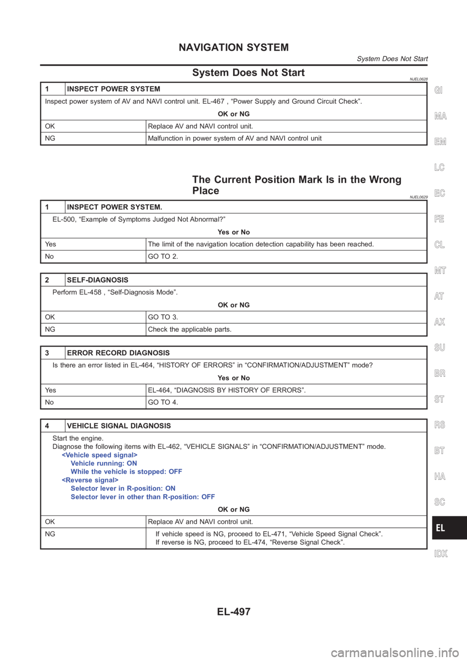
System Does Not StartNJEL0628
1 INSPECT POWER SYSTEM
Inspect power system of AV and NAVI control unit. EL-467 , “Power Supply andGround Circuit Check”.
OK or NG
OK Replace AV and NAVI control unit.
NG Malfunction in power system of AV and NAVI control unit
The Current Position Mark Is in the Wrong
Place
NJEL0629
1 INSPECT POWER SYSTEM.
EL-500, “Example of Symptoms Judged Not Abnormal?”
YesorNo
Yes The limit of the navigation location detection capability has been reached.
No GO TO 2.
2 SELF-DIAGNOSIS
Perform EL-458 , “Self-Diagnosis Mode”.
OK or NG
OK GO TO 3.
NG Check the applicable parts.
3 ERROR RECORD DIAGNOSIS
Is there an error listed in EL-464, “HISTORY OF ERRORS” in “CONFIRMATION/ADJUSTMENT” mode?
YesorNo
Yes EL-464, “DIAGNOSIS BY HISTORY OF ERRORS”.
No GO TO 4.
4 VEHICLE SIGNAL DIAGNOSIS
Start the engine.
Diagnose the following items with EL-462, “VEHICLE SIGNALS” in “CONFIRMATION/ADJUSTMENT” mode.
Vehicle running: ON
While the vehicle is stopped: OFF
Selector lever in R-position: ON
Selector lever in other than R-position: OFF
OK or NG
OK Replace AV and NAVI control unit.
NG If vehicle speed is NG, proceed to EL-471, “Vehicle Speed Signal Check”.
If reverse is NG, proceed to EL-474, “Reverse Signal Check”.
GI
MA
EM
LC
EC
FE
CL
MT
AT
AX
SU
BR
ST
RS
BT
HA
SC
IDX
NAVIGATION SYSTEM
System Does Not Start
EL-497
Page 2834 of 3189
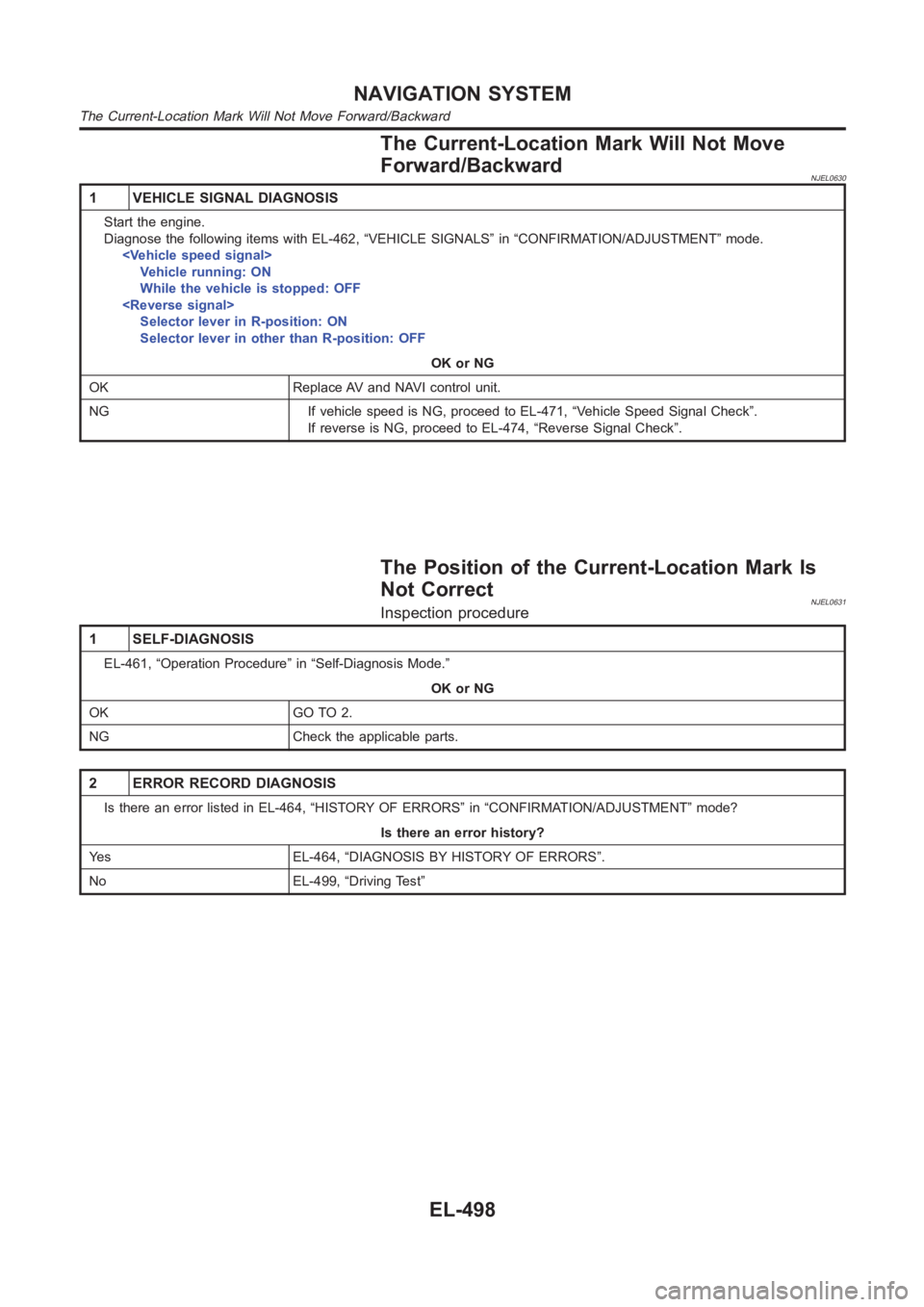
The Current-Location Mark Will Not Move
Forward/Backward
NJEL0630
1 VEHICLE SIGNAL DIAGNOSIS
Start the engine.
Diagnose the following items with EL-462, “VEHICLE SIGNALS” in “CONFIRMATION/ADJUSTMENT” mode.
Vehicle running: ON
While the vehicle is stopped: OFF
Selector lever in R-position: ON
Selector lever in other than R-position: OFF
OK or NG
OK Replace AV and NAVI control unit.
NG If vehicle speed is NG, proceed to EL-471, “Vehicle Speed Signal Check”.
If reverse is NG, proceed to EL-474, “Reverse Signal Check”.
The Position of the Current-Location Mark Is
Not Correct
NJEL0631Inspection procedure
1 SELF-DIAGNOSIS
EL-461, “Operation Procedure” in “Self-Diagnosis Mode.”
OK or NG
OK GO TO 2.
NG Check the applicable parts.
2 ERROR RECORD DIAGNOSIS
Is there an error listed in EL-464, “HISTORY OF ERRORS” in “CONFIRMATION/ADJUSTMENT” mode?
Is there an error history?
Yes EL-464, “DIAGNOSIS BY HISTORY OF ERRORS”.
No EL-499, “Driving Test”
NAVIGATION SYSTEM
The Current-Location Mark Will Not Move Forward/Backward
EL-498
Page 2837 of 3189
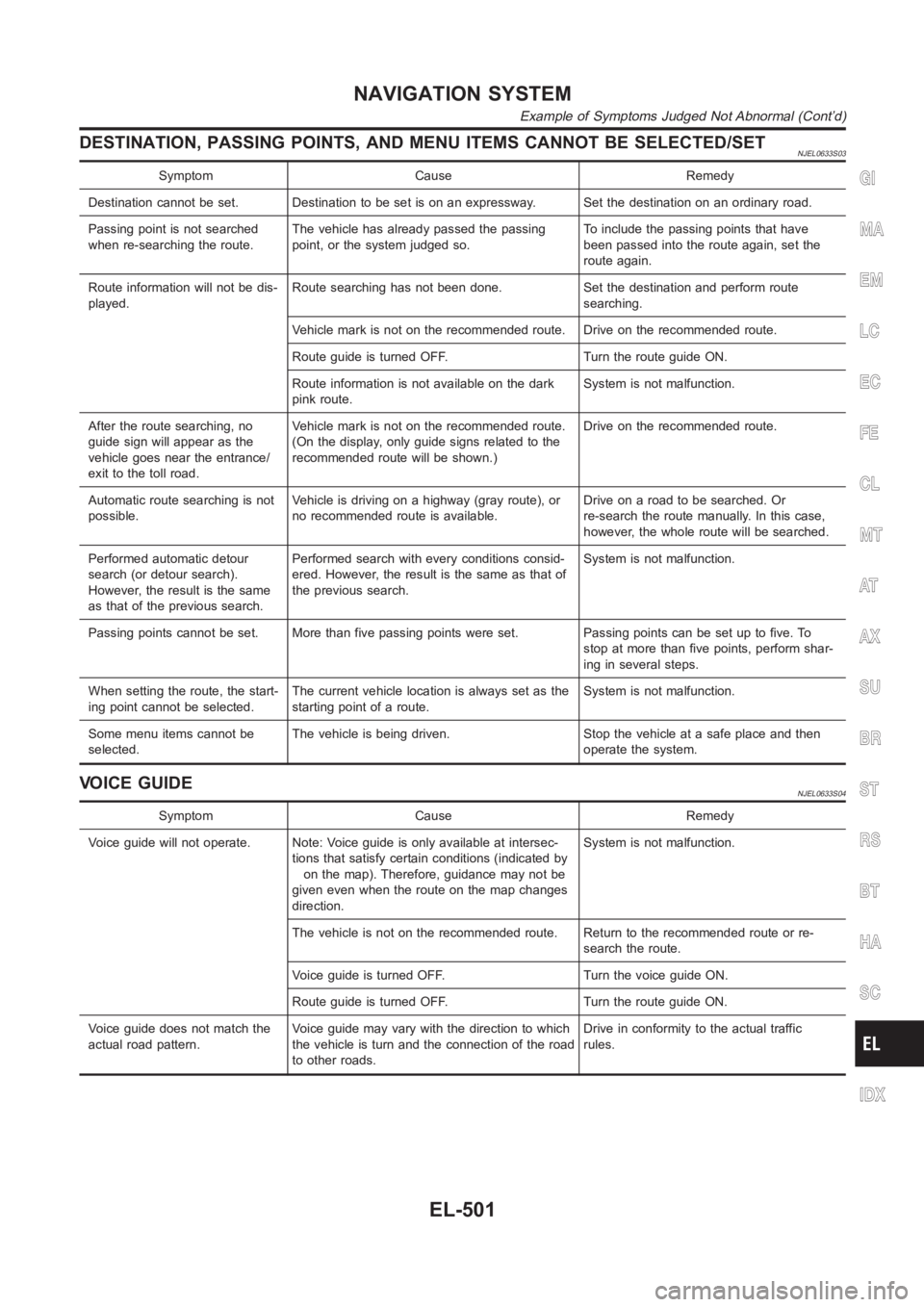
DESTINATION, PASSING POINTS, AND MENU ITEMS CANNOT BE SELECTED/SETNJEL0633S03
Symptom Cause Remedy
Destination cannot be set. Destination to be set is on an expressway. Set the destination on an ordinary road.
Passing point is not searched
when re-searching the route.The vehicle has already passed the passing
point, or the system judged so.To include the passing points that have
been passed into the route again, set the
route again.
Route information will not be dis-
played.Route searching has not been done. Set the destination and perform route
searching.
Vehicle mark is not on the recommended route. Drive on the recommended route.
Route guide is turned OFF. Turn the route guide ON.
Route information is not available on the dark
pink route.System is not malfunction.
After the route searching, no
guide sign will appear as the
vehicle goes near the entrance/
exit to the toll road.Vehicle mark is not on the recommended route.
(On the display, only guide signs related to the
recommended route will be shown.)Drive on the recommended route.
Automatic route searching is not
possible.Vehicle is driving on a highway (gray route), or
no recommended route is available.Drive on a road to be searched. Or
re-search the route manually. In this case,
however, the whole route will be searched.
Performed automatic detour
search (or detour search).
However, the result is the same
as that of the previous search.Performed search with every conditions consid-
ered. However, the result is the same as that of
the previous search.System is not malfunction.
Passing points cannot be set. More than five passing points were set. Passing points can be set up to five. To
stop at more than five points, perform shar-
ing in several steps.
When setting the route, the start-
ing point cannot be selected.The current vehicle location is always set as the
starting point of a route.System is not malfunction.
Some menu items cannot be
selected.The vehicle is being driven. Stop the vehicle at a safe place and then
operate the system.
VOICE GUIDENJEL0633S04
Symptom Cause Remedy
Voice guide will not operate. Note: Voice guide is only available at intersec-
tions that satisfy certain conditions (indicated by
on the map). Therefore, guidance may not be
given even when the route on the map changes
direction.System is not malfunction.
The vehicle is not on the recommended route. Return to the recommended routeorre-
search the route.
Voice guide is turned OFF. Turn the voice guide ON.
Route guide is turned OFF. Turn the route guide ON.
Voice guide does not match the
actual road pattern.Voice guide may vary with the direction to which
the vehicle is turn and the connection of the road
to other roads.Drive in conformity to the actual traffic
rules.
GI
MA
EM
LC
EC
FE
CL
MT
AT
AX
SU
BR
ST
RS
BT
HA
SC
IDX
NAVIGATION SYSTEM
Example of Symptoms Judged Not Abnormal (Cont’d)
EL-501
Page 2842 of 3189
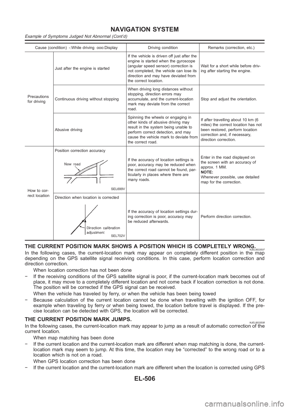
Cause (condition) -:While driving ooo:Display Driving condition Remarks (correction, etc.)
Precautions
for drivingJust after the engine is startedIf the vehicle is driven off just after the
engine is started when the gyroscope
(angular speed sensor) correction is
not completed, the vehicle can lose its
direction and may have deviated from
the correct location.Wait for a short while before driv-
ing after starting the engine.
Continuous driving without stoppingWhen driving long distances without
stopping, direction errors may
accumulate, and the current-location
mark may deviate from the correct
road.Stop and adjust the orientation.
Abusive drivingSpinning the wheels or engaging in
other kinds of abusive driving may
result in the system being unable to
perform correct detection, and may
cause the vehicle mark to deviate from
the correct road.If after travelling about 10 km (6
miles) the correct location has not
been restored, perform location
correction and, if necessary,
direction correction.
How to cor-
rect locationPosition correction accuracy
SEL699V
If the accuracy of location settings is
poor, accuracy may be reduced when
the correct road cannot be found, par-
ticularly in places where there are
many roads.Enter in the road displayed on
the screen with an accuracy of
approx. 1 MM.
NOTE:
Whenever possible, use detailed
map for the correction.
Direction when location is corrected
SEL702V
If the accuracy of location settings dur-
ing correction is poor, accuracy may
be reduced afterwards.Perform direction correction.
THE CURRENT POSITION MARK SHOWS A POSITION WHICH IS COMPLETELY WRONG.NJEL0633S07In the following cases, the current-location mark may appear on completely different position in the map
depending on the GPS satellite signal receiving conditions. In this case,perform location correction and
direction correction.
When location correction has not been done
− If the receiving conditions of the GPS satellite signal is poor, if the current-location mark becomes out of
place, it may move to a completely different location and not come back if location correction is not done.
The position will be corrected if the GPS signal can be received.
When the vehicle has traveled by ferry, or when the vehicle has been being towed
− Because calculation of the current location cannot be done when travelling with the ignition OFF, for
example when traveling by ferry or when being towed, the location before travel is displayed. If the pre-
cise location can be detected with GPS, the location will be corrected.
THE CURRENT POSITION MARK JUMPS.NJEL0633S08In the following cases, the current-location mark may appear to jump as a result of automatic correction of the
current location.
When map matching has been done
− If the current location and the current-location mark are different whenmap matching is done, the current-
location mark may seem to jump. At this time, the location may be “corrected” to the wrong road or to a
location which is not on a road.
When GPS location correction has been done
− If the current location and the current-location mark are different whenthe location is corrected using GPS
NAVIGATION SYSTEM
Example of Symptoms Judged Not Abnormal (Cont’d)
EL-506
Page 2936 of 3189
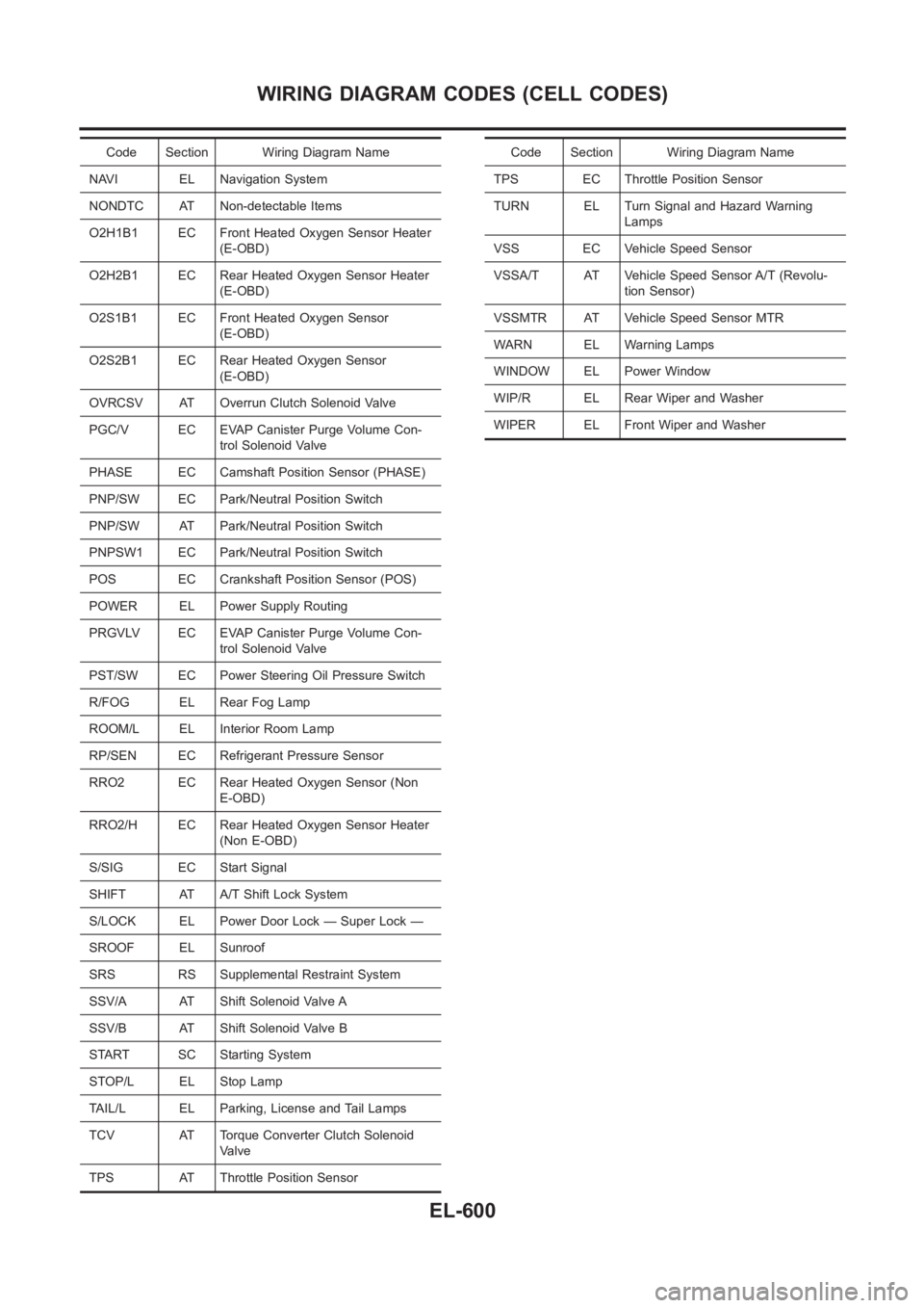
Code Section Wiring Diagram Name
NAVI EL Navigation System
NONDTC AT Non-detectable Items
O2H1B1 EC Front Heated Oxygen Sensor Heater
(E-OBD)
O2H2B1 EC Rear Heated Oxygen Sensor Heater
(E-OBD)
O2S1B1 EC Front Heated Oxygen Sensor
(E-OBD)
O2S2B1 EC Rear Heated Oxygen Sensor
(E-OBD)
OVRCSV AT Overrun Clutch Solenoid Valve
PGC/V EC EVAP Canister Purge Volume Con-
trol Solenoid Valve
PHASE EC Camshaft Position Sensor (PHASE)
PNP/SW EC Park/Neutral Position Switch
PNP/SW AT Park/Neutral Position Switch
PNPSW1 EC Park/Neutral Position Switch
POS EC Crankshaft Position Sensor (POS)
POWER EL Power Supply Routing
PRGVLV EC EVAP Canister Purge Volume Con-
trol Solenoid Valve
PST/SW EC Power Steering Oil Pressure Switch
R/FOG EL Rear Fog Lamp
ROOM/L EL Interior Room Lamp
RP/SEN EC Refrigerant Pressure Sensor
RRO2 EC Rear Heated Oxygen Sensor (Non
E-OBD)
RRO2/H EC Rear Heated Oxygen Sensor Heater
(Non E-OBD)
S/SIG EC Start Signal
SHIFT AT A/T Shift Lock System
S/LOCK EL Power Door Lock — Super Lock —
SROOF EL Sunroof
SRS RS Supplemental Restraint System
SSV/A AT Shift Solenoid Valve A
SSV/B AT Shift Solenoid Valve B
START SC Starting System
STOP/L EL Stop Lamp
TAIL/L EL Parking, License and Tail Lamps
TCV AT Torque Converter Clutch Solenoid
Valve
TPS AT Throttle Position SensorCode Section Wiring Diagram Name
TPS EC Throttle Position Sensor
TURN EL Turn Signal and Hazard Warning
Lamps
VSS EC Vehicle Speed Sensor
VSSA/T AT Vehicle Speed Sensor A/T (Revolu-
tion Sensor)
VSSMTR AT Vehicle Speed Sensor MTR
WARN EL Warning Lamps
WINDOW EL Power Window
WIP/R EL Rear Wiper and Washer
WIPER EL Front Wiper and Washer
WIRING DIAGRAM CODES (CELL CODES)
EL-600