Page 1609 of 3189
![NISSAN ALMERA N16 2003 Electronic Repair Manual DTC P0734 A/T 4TH GEAR FUNCTION
AT-153
[EURO-OBD]
D
E
F
G
H
I
J
K
L
MA
B
AT
3. Select “4TH GR FNCTN P0734” of “DTC WORK SUPPORT”
mode for “A/T” with CONSULT-II and touch “START� NISSAN ALMERA N16 2003 Electronic Repair Manual DTC P0734 A/T 4TH GEAR FUNCTION
AT-153
[EURO-OBD]
D
E
F
G
H
I
J
K
L
MA
B
AT
3. Select “4TH GR FNCTN P0734” of “DTC WORK SUPPORT”
mode for “A/T” with CONSULT-II and touch “START�](/manual-img/5/57350/w960_57350-1608.png)
DTC P0734 A/T 4TH GEAR FUNCTION
AT-153
[EURO-OBD]
D
E
F
G
H
I
J
K
L
MA
B
AT
3. Select “4TH GR FNCTN P0734” of “DTC WORK SUPPORT”
mode for “A/T” with CONSULT-II and touch “START”.
4. Accelerate vehicle to 55 to 65 km/h (34 to 40 MPH) under the
following condition and release the accelerator pedal com-
pletely.
THROTTLE POSI: Less than 5.5/8 (at all times during step 4)
Selector lever: D position (OD “ON”)
●Check that “GEAR” shows “3” after releasing pedal.
5. Depress accelerator pedal steadily with 1.0/8 - 2.0/8 of “THROT-
TLE POSI” from a speed of 55 to 65 km/h (34 to 40 MPH) until
“TESTING” has turned to “STOP VEHICLE” or “COMPLETED”.
(It will take approximately 3 seconds.)
If the check result NG appears on CONSULT-II screen, go to AT-155, "
Diagnostic Procedure" .
If “STOP VEHICLE” appears on CONSULT-II screen, go to following step.
●Check that “GEAR” shows “4” when depressing accelerator pedal with 1.0/8 - 2.0/8 of “THROTTLE
POSI”.
●If “TESTING” does not appear on CONSULT-II for a long time, select “SELF-DIAGNOSIS” for
“ENGINE”. In case a 1st trip DTC other than P0734 is shown, refer to applicable “TROUBLE DIAG-
NOSIS FOR DTC”.
6. Stop vehicle.
7. Follow the instruction displayed. (Check for normal shifting referring to the table below.)
8. Make sure that “OK” is displayed. (If “NG” is displayed, go to AT-155, "
Diagnostic Procedure" .)
Refer to AT- 5 1 5 , "
Shift Schedule" .
With GST
Follow the procedure “With CONSULT-II”.
Vehicle conditionGear on actual transmission shift pattern when
screen is changed to 1 → 2 → 3 → 4
No malfunction exists 1 → 2 → 3 → 4
Malfunction for P0734 exists. 1 → 2 → 2 → 1
SAT971J
Page 1717 of 3189
TROUBLE DIAGNOSIS — BASIC INSPECTION
AT-261
[EXC.F/EURO-OBD]
D
E
F
G
H
I
J
K
L
MA
B
AT
TROUBLE DIAGNOSIS — BASIC INSPECTIONPFP:00000
A/T Fluid CheckECS007QR
FLUID LEAKAGE CHECK
1. Clean area suspected of leaking. — for example, mating surface
of converter housing and transmission case.
2. Start engine, apply foot brake, place selector lever in “D” posi-
tion and wait a few minutes.
3. Stop engine.
4. Check for fluid leakage.
FLUID CONDITION CHECK
FLUID LEVEL CHECK
Refer to AT- 2 6 1 , "A/T Fluid Check" .
SAT767B
SAT288G
Fluid color Suspected problem
Dark or black with burned odor Wear of frictional material
Milky pink Water contamination — Road water
entering through filler tube or breather
Varnished fluid, light to dark brown and
tackyOxidation — Over or under filling, —
Overheating
SAT638A
Page 1724 of 3189
![NISSAN ALMERA N16 2003 Electronic Repair Manual AT-268
[EXC.F/EURO-OBD]
TROUBLE DIAGNOSIS — BASIC INSPECTION
1. CHECK BEFORE ENGINE IS STARTED
1. CHECK O/D OFF INDICATOR LAMP
1. Park vehicle on flat surface.
2. Turn ignition switch to “OFF” p NISSAN ALMERA N16 2003 Electronic Repair Manual AT-268
[EXC.F/EURO-OBD]
TROUBLE DIAGNOSIS — BASIC INSPECTION
1. CHECK BEFORE ENGINE IS STARTED
1. CHECK O/D OFF INDICATOR LAMP
1. Park vehicle on flat surface.
2. Turn ignition switch to “OFF” p](/manual-img/5/57350/w960_57350-1723.png)
AT-268
[EXC.F/EURO-OBD]
TROUBLE DIAGNOSIS — BASIC INSPECTION
1. CHECK BEFORE ENGINE IS STARTED
1. CHECK O/D OFF INDICATOR LAMP
1. Park vehicle on flat surface.
2. Turn ignition switch to “OFF” position.
3. Move selector lever to “P” position.
4. Set overdrive control switch to “ON” position.
5. Turn ignition switch to “ON” position. (Do not start engine.)
6. Does O/D OFF indicator lamp come on for about 2 seconds?
Ye s o r N o
Yes >> GO TO 2
No >> Stop ROAD TEST. GO TO AT- 3 0 9 , "
1. O/D OFF Indica-
tor Lamp Does Not Come On" .
2. CHECK O/D OFF INDICATOR LAMP
Does O/D OFF indicator lamp flicker for about 8 seconds?
Ye s o r N o
Yes >> Perform self-diagnosis and check NG items on the
DIAGNOSTIC WORKSHEET. Refer to AT- 2 5 6
and AT-
250, "SELF-DIAGNOSTIC PROCEDURE (WITHOUT
CONSULT-II)" .
No >> 1. Turn ignition switch to “OFF” position.
2. Perform self-diagnosis and note NG items.
Refer to AT- 2 5 0 , "
SELF-DIAGNOSTIC PROCEDURE
(WITHOUT CONSULT-II)" .
3. GO TO AT-269, "
2. CHECK AT IDLE" .
SAT774B
MCIA3103E
MCIA3103E
Page 1856 of 3189
![NISSAN ALMERA N16 2003 Electronic Repair Manual AT-400
[ALL]
A/T SHIFT LOCK SYSTEM
Diagnostic Procedure
ECS007SV
SYMPTOM 1:
●Selector lever cannot be moved from “P” position with key in ON position and brake pedal
applied.
●Selec NISSAN ALMERA N16 2003 Electronic Repair Manual AT-400
[ALL]
A/T SHIFT LOCK SYSTEM
Diagnostic Procedure
ECS007SV
SYMPTOM 1:
●Selector lever cannot be moved from “P” position with key in ON position and brake pedal
applied.
●Selec](/manual-img/5/57350/w960_57350-1855.png)
AT-400
[ALL]
A/T SHIFT LOCK SYSTEM
Diagnostic Procedure
ECS007SV
SYMPTOM 1:
●Selector lever cannot be moved from “P” position with key in ON position and brake pedal
applied.
●Selector lever can be moved from “P” position with key in ON position and brake pedal released.
●Selector lever can be moved from “P” position when key is removed from key cylinder.
SYMPTOM 2:
Ignition key cannot be removed when selector lever is set to “P” position. It can be removed when
selector lever is set to any position except “P”.
1. CHECK KEY INTERLOCK CABLE
Check key interlock cable for damage.
OK or NG
OK >> GO TO 2
NG >> Repair key interlock cable. Refer to AT- 4 0 4 , "
KEY INTERLOCK CABLE" .
2. CHECK SELECTOR LEVER POSITION
Check selector lever position for damage.
OK or NG
OK >> GO TO 3
NG >> Check selector lever. Refer to AT- 4 0 8 , "
Park/Neutral Position (PNP) Switch Adjustment" .
3. CHECK POWER SOURCE
1. Turn ignition switch to “ON” position.
(Do not start engine.)
2. Check voltage between stop lamp switch harness terminal 1 and ground.
OK or NG
OK >> GO TO 4
NG >> Check the following items:
1. Harness for short or open between battery and stop
lamp switch harness terminal 1
2. Fuse
3. Ignition switch (Refer to EL-11, "POWER SUPPLY
ROUTING".) Voltage: Battery voltage
MCIB0003E
Page 1857 of 3189
![NISSAN ALMERA N16 2003 Electronic Repair Manual A/T SHIFT LOCK SYSTEM
AT-401
[ALL]
D
E
F
G
H
I
J
K
L
MA
B
AT
4.CHECK INPUT SIGNAL (A/T DEVICE)
Turn ignition switch to “ON” position.
(Do not start engine.)
●Check voltage between A/T device har NISSAN ALMERA N16 2003 Electronic Repair Manual A/T SHIFT LOCK SYSTEM
AT-401
[ALL]
D
E
F
G
H
I
J
K
L
MA
B
AT
4.CHECK INPUT SIGNAL (A/T DEVICE)
Turn ignition switch to “ON” position.
(Do not start engine.)
●Check voltage between A/T device har](/manual-img/5/57350/w960_57350-1856.png)
A/T SHIFT LOCK SYSTEM
AT-401
[ALL]
D
E
F
G
H
I
J
K
L
MA
B
AT
4.CHECK INPUT SIGNAL (A/T DEVICE)
Turn ignition switch to “ON” position.
(Do not start engine.)
●Check voltage between A/T device harness terminal 2 and ground.
OK or NG
OK >> GO TO 5
NG >> Check the following items:
1. Harness for short and open between battery and stop
lamp switch harness connector 1.
2. Harness for short or open between stop lamp switch harness connector 2 and A/T device har-
ness connector 2.
3. Fuse
4. Stop lamp switch (Refer to AT-403, "
A/T DEVICE CHECK" .)
5.CHECK GROUND CIRCUIT
1. Turn ignition switch to “OFF” position.
2. Disconnect A/T device harness connector.
3. Check continuity between A/T device harness terminal 3 and ground.
If OK, check harness for short to ground and short to power.
OK or NG
OK >> GO TO 6
NG >> Repair open circuit or short to ground or short to power
in harness or connectors. Voltage:
Brake pedal depressed:
Battery voltage
Brake pedal released:
0V
MCIB0004E
Continuity should exist.
SAT009K
Page 2000 of 3189

ATC-20
LUBRICANT
LUBRICANT
PFP:KLG00
Maintenance of Lubricant Quantity in CompressorEJS001Z4
The lubricant in the compressor circulates through the system with the refrigerant. Add lubricant to compres-
sor when replacing any component or after a large gas leakage occurred. It is important to maintain the speci-
fied amount.
If lubricant quantity is not maintained properly, the following malfunctions may result:
●Lack of lubricant: May lead to a seized compressor
●Excessive lubricant: Inadequate cooling (thermal exchange interference)
LUBRICANT
LUBRICANT RETURN OPERATION
Adjust the lubricant quantity according to the test group shown below.
1. CHECK LUBRICANT RETURN OPERATION
Can lubricant return operation be performed?
●A/C system works properly.
●There is no evidence of a large amount of lubricant leakage.
Ye s o r N o
Yes >> GO TO 2.
No >> GO TO 3.
2. PERFORM LUBRICANT RETURN OPERATION, PROCEEDING AS FOLLOWS:
1. Start engine, and set the following conditions:
–Test condition
Engine speed: Idling to 1,200 rpm
A/C or AUTO switch: ON
Blower speed: Max. position
Temp. control: Optional [Set so that intake air temperature is 25 to 30°C (77 to 86°F).]
Intake position: Recirculation (REC)
2. Perform lubricant return operation for about 10 minutes.
3. Stop engine.
CAUTION:
If excessive lubricant leakage is noted, do not perform the lubricant return operation.
>> GO TO 3.
3. CHECK COMPRESSOR
Should the compressor be replaced?
Ye s o r N o
Ye s > > G o t o AT C - 2 1 , "LUBRICANT ADJUSTING PROCEDURE FOR COMPRESSOR REPLACE-
MENT" .
No >> GO TO 4.Name Nissan A/C System Oil Type S
Part number KLH00-PAGS0
Page 2003 of 3189

AIR CONDITIONER CONTROL
ATC-23
C
D
E
F
G
H
I
K
L
MA
B
AT C
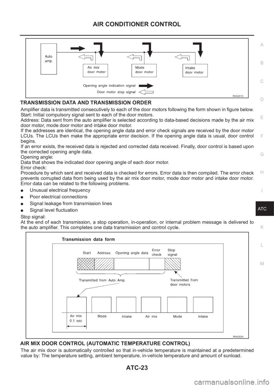
TRANSMISSION DATA AND TRANSMISSION ORDER
Amplifier data is transmitted consecutively to each of the door motors following the form shown in figure below.
Start: Initial compulsory signal sent to each of the door motors.
Address: Data sent from the auto amplifier is selected according to data-based decisions made by the air mix
door motor, mode door motor and intake door motor.
If the addresses are identical, the opening angle data and error check signals are received by the door motor
LCUs. The LCUs then make the appropriate error decision. If the opening angle data is usual, door control
begins.
If an error exists, the received data is rejected and corrected data received. Finally, door control is based upon
the corrected opening angle data.
Opening angle:
Data that shows the indicated door opening angle of each door motor.
Error check:
Procedure by which sent and received data is checked for errors. Error data is then compiled. The error check
prevents corrupted data from being used by the air mix door motor, mode door motor and intake door motor.
Error data can be related to the following problems.
●Unusual electrical frequency
●Poor electrical connections
●Signal leakage from transmission lines
●Signal level fluctuation
Stop signal:
At the end of each transmission, a stop operation, in-operation, or internal problem message is delivered to
the auto amplifier. This completes one data transmission and control cycle.
AIR MIX DOOR CONTROL (AUTOMATIC TEMPERATURE CONTROL)
The air mix door is automatically controlled so that in-vehicle temperature is maintained at a predetermined
value by: The temperature setting, ambient temperature, in-vehicle temperature and amount of sunload.
RHA351H
RHA352H
Page 2074 of 3189

ATC-94
TROUBLE DIAGNOSIS
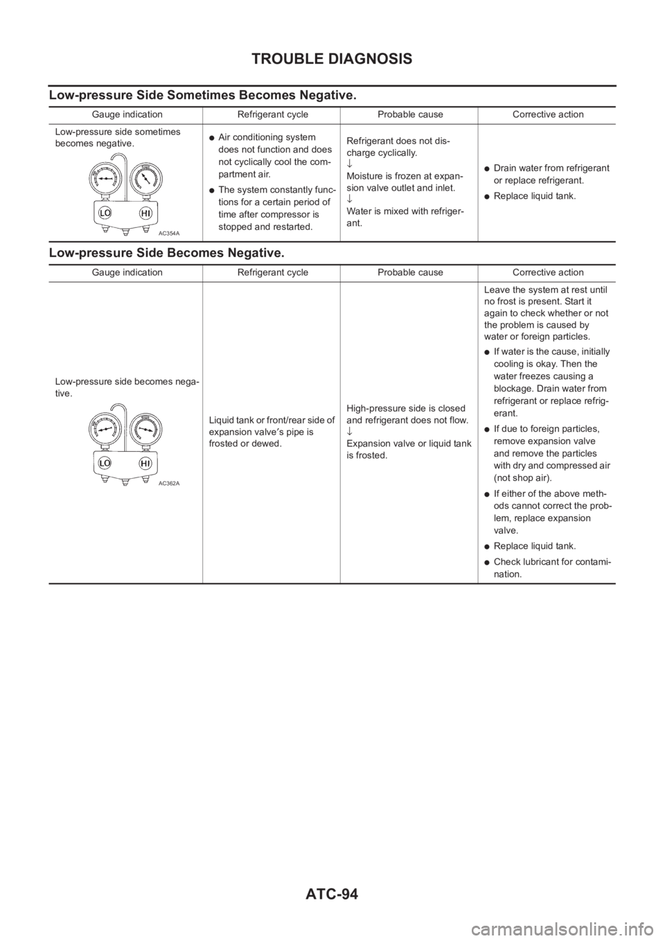
Low-pressure Side Sometimes Becomes Negative.
Low-pressure Side Becomes Negative.
Gauge indication Refrigerant cycle Probable cause Corrective action
Low-pressure side sometimes
becomes negative.
●Air conditioning system
does not function and does
not cyclically cool the com-
partment air.
●The system constantly func-
tions for a certain period of
time after compressor is
stopped and restarted.Refrigerant does not dis-
charge cyclically.
↓
Moisture is frozen at expan-
sion valve outlet and inlet.
↓
Water is mixed with refriger-
ant.
●Drain water from refrigerant
or replace refrigerant.
●Replace liquid tank.
AC354A
Gauge indication Refrigerant cycle Probable cause Corrective action
Low-pressure side becomes nega-
tive.
Liquid tank or front/rear side of
expansion valve′s pipe is
frosted or dewed.High-pressure side is closed
and refrigerant does not flow.
↓
Expansion valve or liquid tank
is frosted.Leave the system at rest until
no frost is present. Start it
again to check whether or not
the problem is caused by
water or foreign particles.
●If water is the cause, initially
cooling is okay. Then the
water freezes causing a
blockage. Drain water from
refrigerant or replace refrig-
erant.
●If due to foreign particles,
remove expansion valve
and remove the particles
with dry and compressed air
(not shop air).
●If either of the above meth-
ods cannot correct the prob-
lem, replace expansion
valve.
●Replace liquid tank.
●Check lubricant for contami-
nation.
AC362A