2003 LEXUS LS430 brake sensor
[x] Cancel search: brake sensorPage 2487 of 4500
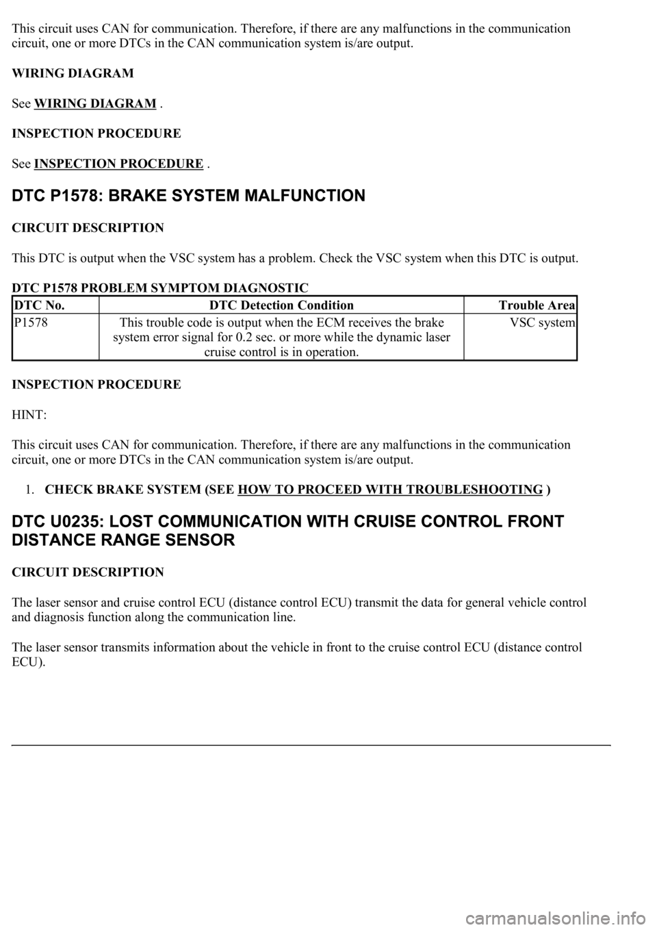
This circuit uses CAN for communication. Therefore, if there are any malfunctions in the communication
circuit, one or more DTCs in the CAN communication system is/are output.
WIRING DIAGRAM
See WIRING DIAGRAM
.
INSPECTION PROCEDURE
See INSPECTION PROCEDURE
.
CIRCUIT DESCRIPTION
This DTC is output when the VSC system has a problem. Check the VSC system when this DTC is output.
DTC P1578 PROBLEM SYMPTOM DIAGNOSTIC
INSPECTION PROCEDURE
HINT:
This circuit uses CAN for communication. Therefore, if there are any malfunctions in the communication
circuit, one or more DTCs in the CAN communication system is/are output.
1.CHECK BRAKE SYSTEM (SEE HOW TO PROCEED WITH TROUBLESHOOTING
)
CIRCUIT DESCRIPTION
The laser sensor and cruise control ECU (distance control ECU) transmit the data for general vehicle control
and diagnosis function along the communication line.
The laser sensor transmits information about the vehicle in front to the cruise control ECU (distance control
ECU).
DTC No.DTC Detection ConditionTrouble Area
P1578This trouble code is output when the ECM receives the brake
system error signal for 0.2 sec. or more while the dynamic laser
cruise control is in operation.VSC system
Page 2526 of 4500
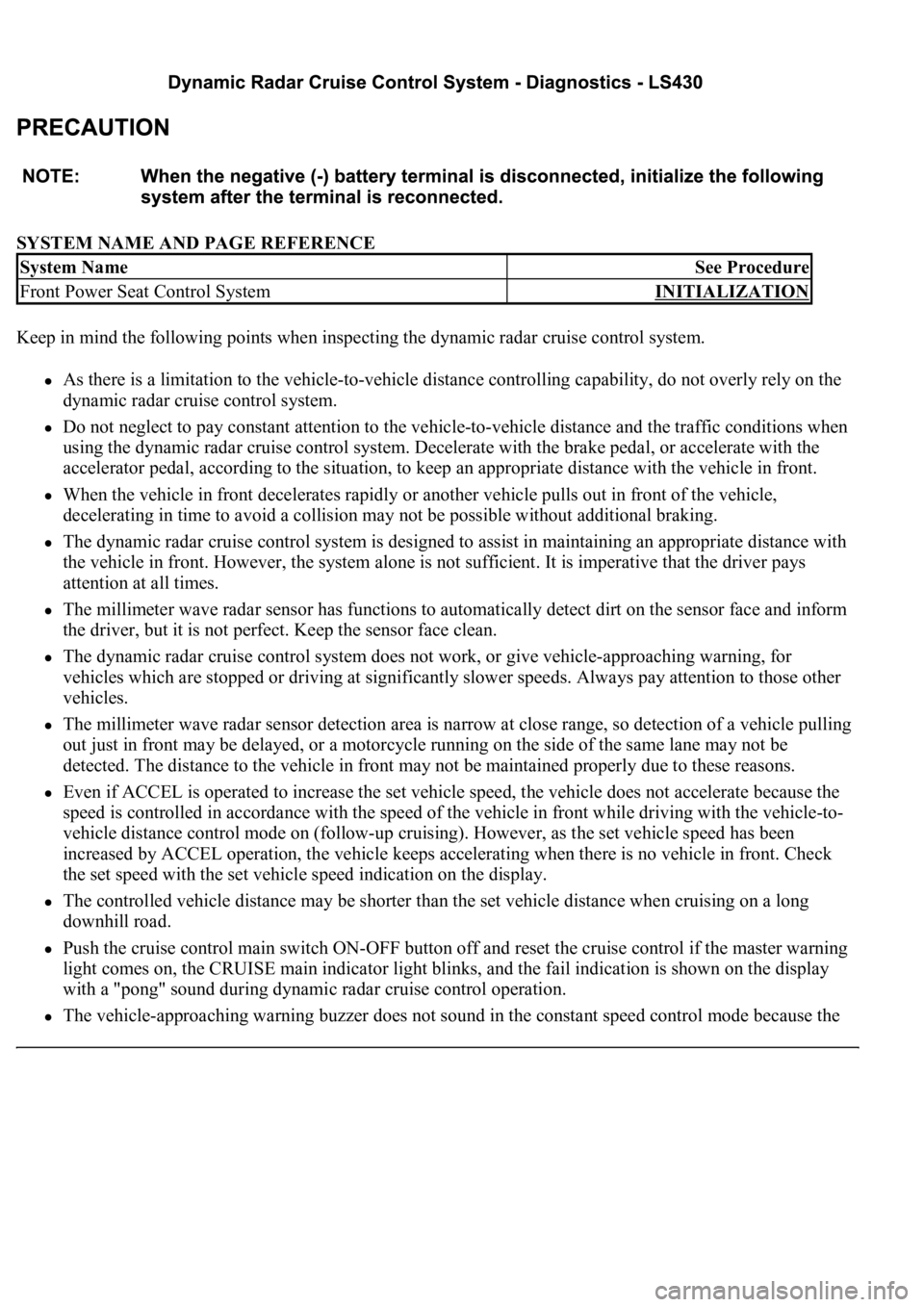
SYSTEM NAME AND PAGE REFERENCE
Keep in mind the following points when inspecting the dynamic radar cruise control system.
As there is a limitation to the vehicle-to-vehicle distance controlling capability, do not overly rely on the
dynamic radar cruise control system.
Do not neglect to pay constant attention to the vehicle-to-vehicle distance and the traffic conditions when
using the dynamic radar cruise control system. Decelerate with the brake pedal, or accelerate with the
accelerator pedal, according to the situation, to keep an appropriate distance with the vehicle in front.
When the vehicle in front decelerates rapidly or another vehicle pulls out in front of the vehicle,
decelerating in time to avoid a collision may not be possible without additional braking.
The dynamic radar cruise control system is designed to assist in maintaining an appropriate distance with
the vehicle in front. However, the system alone is not sufficient. It is imperative that the driver pays
attention at all times.
The millimeter wave radar sensor has functions to automatically detect dirt on the sensor face and inform
the driver, but it is not perfect. Keep the sensor face clean.
The dynamic radar cruise control system does not work, or give vehicle-approaching warning, for
vehicles which are stopped or driving at significantly slower speeds. Always pay attention to those other
vehicles.
The millimeter wave radar sensor detection area is narrow at close range, so detection of a vehicle pulling
out just in front may be delayed, or a motorcycle running on the side of the same lane may not be
detected. The distance to the vehicle in front may not be maintained properly due to these reasons.
Even if ACCEL is operated to increase the set vehicle speed, the vehicle does not accelerate because the
speed is controlled in accordance with the speed of the vehicle in front while driving with the vehicle-to-
vehicle distance control mode on (follow-up cruising). However, as the set vehicle speed has been
increased by ACCEL operation, the vehicle keeps accelerating when there is no vehicle in front. Check
the set speed with the set vehicle speed indication on the display.
The controlled vehicle distance may be shorter than the set vehicle distance when cruising on a long
downhill road.
Push the cruise control main switch ON-OFF button off and reset the cruise control if the master warning
light comes on, the CRUISE main indicator light blinks, and the fail indication is shown on the display
with a "pong" sound during dynamic radar cruise control operation.
The vehicle-approaching warning buzzer does not sound in the constant speed control mode because the
System NameSee Procedure
Front Power Seat Control SystemINITIALIZATION
Page 2532 of 4500
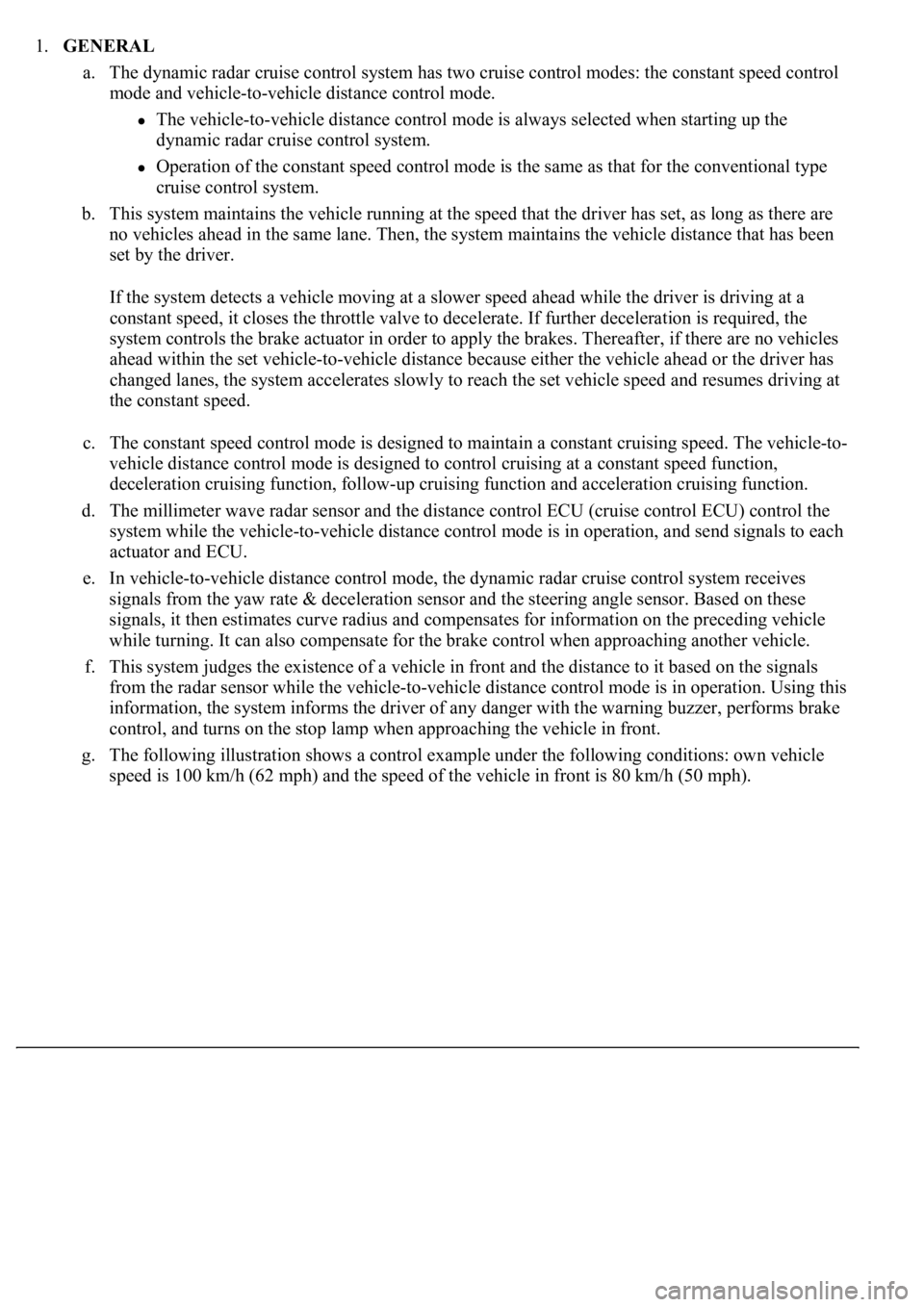
1.GENERAL
a. The dynamic radar cruise control system has two cruise control modes: the constant speed control
mode and vehicle-to-vehicle distance control mode.
The vehicle-to-vehicle distance control mode is always selected when starting up the
dynamic radar cruise control system.
Operation of the constant speed control mode is the same as that for the conventional type
cruise control system.
b. This system maintains the vehicle running at the speed that the driver has set, as long as there are
no vehicles ahead in the same lane. Then, the system maintains the vehicle distance that has been
set by the driver.
If the system detects a vehicle moving at a slower speed ahead while the driver is driving at a
constant speed, it closes the throttle valve to decelerate. If further deceleration is required, the
system controls the brake actuator in order to apply the brakes. Thereafter, if there are no vehicles
ahead within the set vehicle-to-vehicle distance because either the vehicle ahead or the driver has
changed lanes, the system accelerates slowly to reach the set vehicle speed and resumes driving at
the constant speed.
c. The constant speed control mode is designed to maintain a constant cruising speed. The vehicle-to-
vehicle distance control mode is designed to control cruising at a constant speed function,
deceleration cruising function, follow-up cruising function and acceleration cruising function.
d. The millimeter wave radar sensor and the distance control ECU (cruise control ECU) control the
system while the vehicle-to-vehicle distance control mode is in operation, and send signals to each
actuator and ECU.
e. In vehicle-to-vehicle distance control mode, the dynamic radar cruise control system receives
signals from the yaw rate & deceleration sensor and the steering angle sensor. Based on these
signals, it then estimates curve radius and compensates for information on the preceding vehicle
while turning. It can also compensate for the brake control when approaching another vehicle.
f. This system judges the existence of a vehicle in front and the distance to it based on the signals
from the radar sensor while the vehicle-to-vehicle distance control mode is in operation. Using this
information, the system informs the driver of any danger with the warning buzzer, performs brake
control, and turns on the stop lamp when approaching the vehicle in front.
g. The following illustration shows a control example under the following conditions: own vehicle
speed is 100 km/h (62 mph) and the speed of the vehicle in front is 80 km/h (50 mph).
Page 2537 of 4500
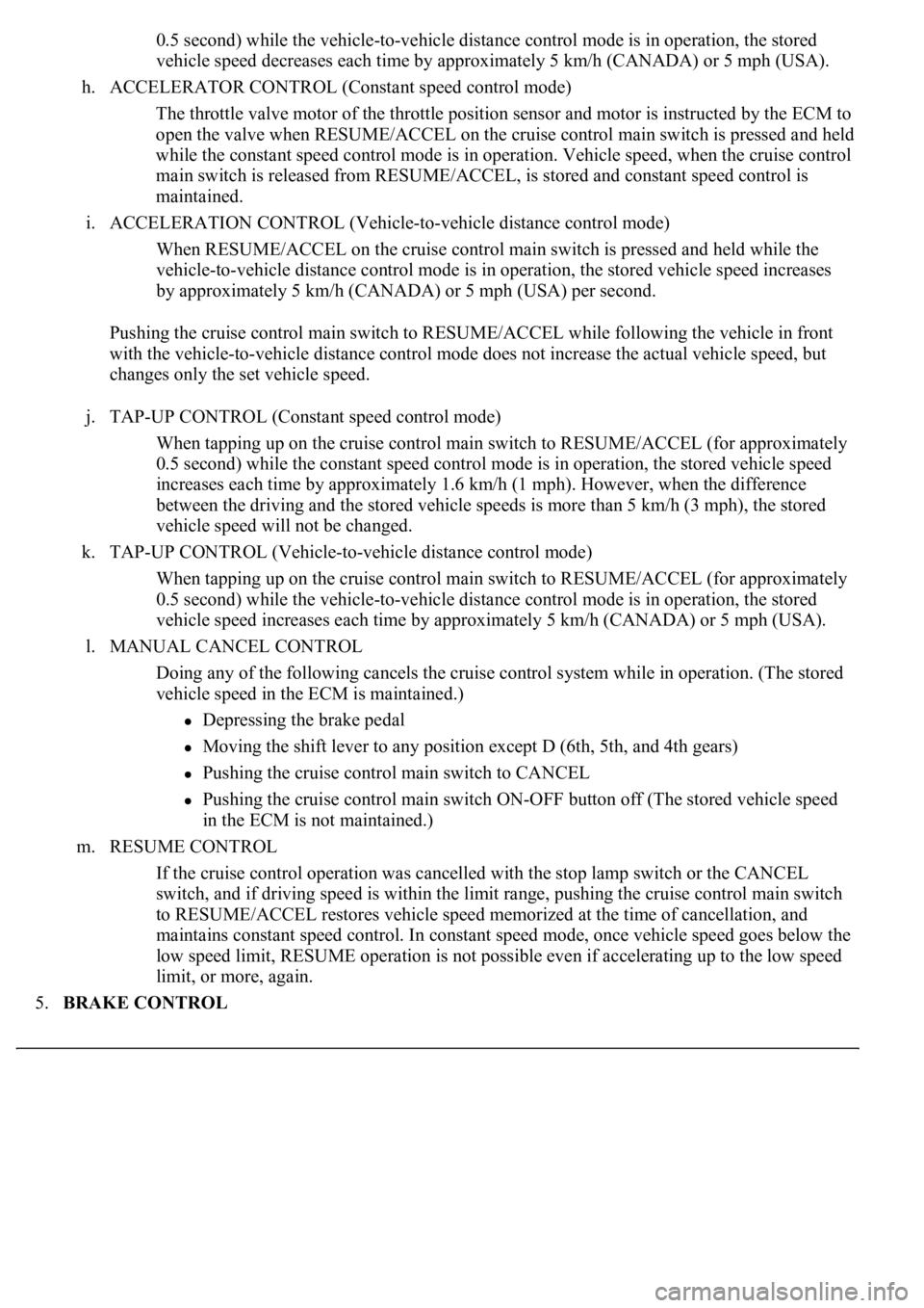
0.5 second) while the vehicle-to-vehicle distance control mode is in operation, the stored
vehicle speed decreases each time by approximately 5 km/h (CANADA) or 5 mph (USA).
h. ACCELERATOR CONTROL (Constant speed control mode)
The throttle valve motor of the throttle position sensor and motor is instructed by the ECM to
open the valve when RESUME/ACCEL on the cruise control main switch is pressed and held
while the constant speed control mode is in operation. Vehicle speed, when the cruise control
main switch is released from RESUME/ACCEL, is stored and constant speed control is
maintained.
i. ACCELERATION CONTROL (Vehicle-to-vehicle distance control mode)
When RESUME/ACCEL on the cruise control main switch is pressed and held while the
vehicle-to-vehicle distance control mode is in operation, the stored vehicle speed increases
by approximately 5 km/h (CANADA) or 5 mph (USA) per second.
Pushing the cruise control main switch to RESUME/ACCEL while following the vehicle in front
with the vehicle-to-vehicle distance control mode does not increase the actual vehicle speed, but
changes only the set vehicle speed.
j. TAP-UP CONTROL (Constant speed control mode)
When tapping up on the cruise control main switch to RESUME/ACCEL (for approximately
0.5 second) while the constant speed control mode is in operation, the stored vehicle speed
increases each time by approximately 1.6 km/h (1 mph). However, when the difference
between the driving and the stored vehicle speeds is more than 5 km/h (3 mph), the stored
vehicle speed will not be changed.
k. TAP-UP CONTROL (Vehicle-to-vehicle distance control mode)
When tapping up on the cruise control main switch to RESUME/ACCEL (for approximately
0.5 second) while the vehicle-to-vehicle distance control mode is in operation, the stored
vehicle speed increases each time by approximately 5 km/h (CANADA) or 5 mph (USA).
l. MANUAL CANCEL CONTROL
<00270052004c0051004a000300440051005c00030052004900030057004b0048000300490052004f004f0052005a004c0051004a000300460044005100460048004f005600030057004b00480003004600550058004c005600480003004600520051005700
550052004f00030056005c00560057004800500003005a004b[ile in operation. (The stored
vehicle speed in the ECM is maintained.)
Depressing the brake pedal
<003000520059004c0051004a00030057004b004800030056004b004c004900570003004f0048005900480055000300570052000300440051005c0003005300520056004c0057004c0052005100030048005b0046004800530057000300270003000b001900
57004b000f000300180057004b000f00030044005100470003[4th gears)
Pushing the cruise control main switch to CANCEL
Pushing the cruise control main switch ON-OFF button off (The stored vehicle speed
in the ECM is not maintained.)
m. RESUME CONTROL
If the cruise control operation was cancelled with the stop lamp switch or the CANCEL
switch, and if driving speed is within the limit range, pushing the cruise control main switch
to RESUME/ACCEL restores vehicle speed memorized at the time of cancellation, and
maintains constant speed control. In constant speed mode, once vehicle speed goes below the
low speed limit, RESUME operation is not possible even if accelerating up to the low speed
limit, or more, again.
5.BRAKE CONTROL
Page 2570 of 4500
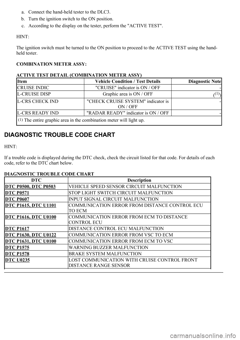
a. Connect the hand-held tester to the DLC3.
b. Turn the ignition switch to the ON position.
c. According to the display on the tester, perform the "ACTIVE TEST".
HINT:
The ignition switch must be turned to the ON position to proceed to the ACTIVE TEST using the hand-
held tester.
COMBINATION METER ASSY:
ACTIVE TEST DETAIL (COMBINATION METER ASSY)
HINT:
If a trouble code is displayed during the DTC check, check the circuit listed for that code. For details of each
code, refer to the DTC chart below.
DIAGNOSTIC TROUBLE CODE CHART
ItemVehicle Condition / Test DetailsDiagnostic Note
CRUISE INDIC"CRUISE" indicator is ON / OFF-
L-CRUISE DISPGraphic area is ON / OFF((1))
L-CRS CHECK IND"CHECK CRUISE SYSTEM" indicator is
ON / OFF-
L-CRS READY IND"RADAR READY" indicator is ON / OFF-
(1)The entire graphic area in the combination meter will light up.
DTCDescription
DTC P0500, DTC P0503VEHICLE SPEED SENSOR CIRCUIT MALFUNCTION
DTC P0571STOP LIGHT SWITCH CIRCUIT MALFUNCTION
DTC P0607INPUT SIGNAL CIRCUIT MALFUNCTION
DTC P1615, DTC U1101COMMUNICATION ERROR FROM DISTANCE CONTROL ECU
TO ECM
DTC P1616, DTC U0100COMMUNICATION ERROR FROM ECM TO DISTANCE
CONTROL ECU
DTC P1617DISTANCE CONTROL ECU MALFUNCTION
DTC P1630, DTC U0122COMMUNICATION ERROR FROM VSC TO ECM
DTC P1631, DTC U0100COMMUNICATION ERROR FROM ECM TO VSC
DTC P1575WARNING BUZZER MALFUNCTION
DTC P1578BRAKE SYSTEM MALFUNCTION
DTC U0235LOST COMMUNICATION WITH CRUISE CONTROL FRONT
DISTANCE RANGE SENSOR
Page 2583 of 4500
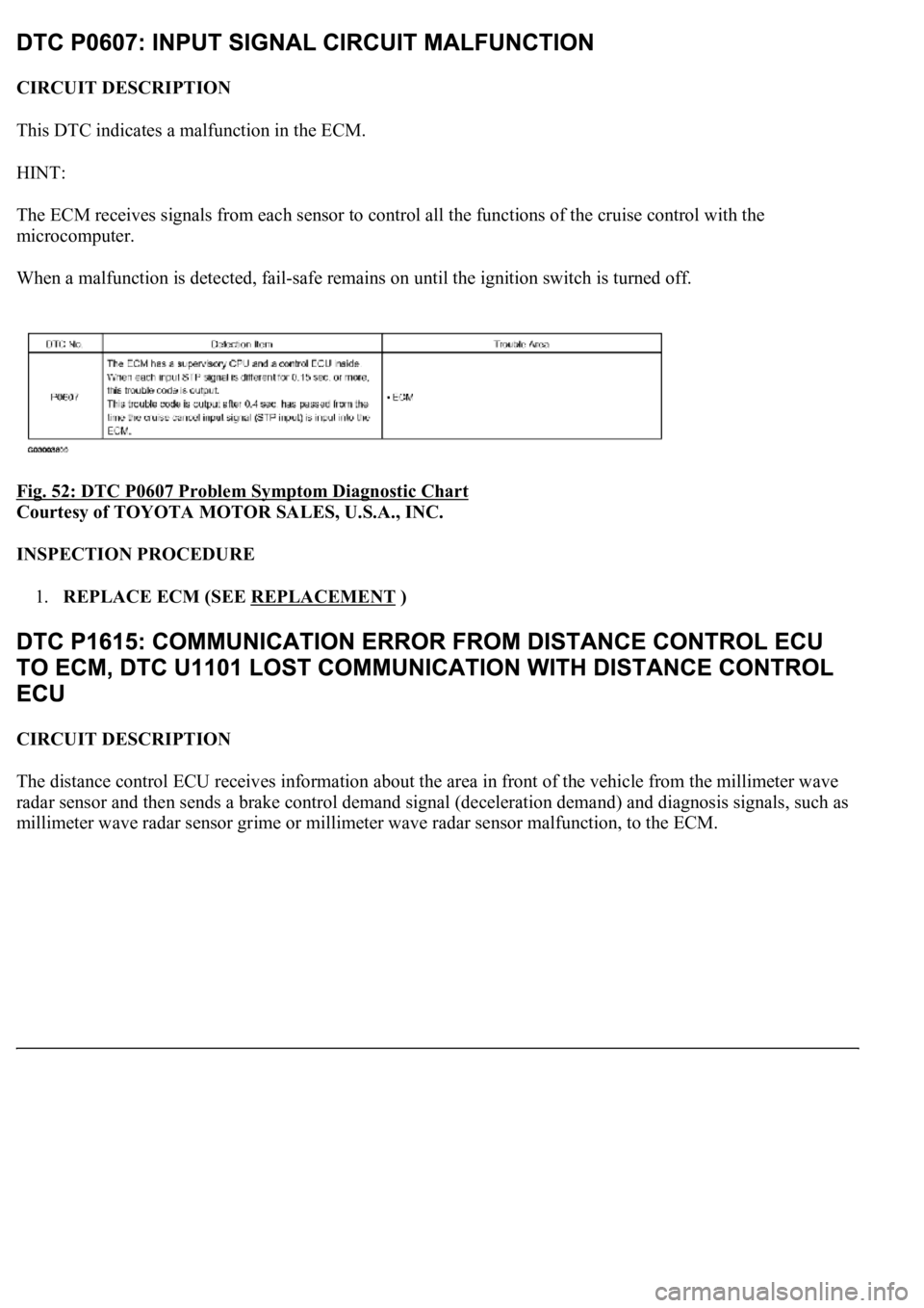
CIRCUIT DESCRIPTION
This DTC indicates a malfunction in the ECM.
HINT:
The ECM receives signals from each sensor to control all the functions of the cruise control with the
microcomputer.
When a malfunction is detected, fail-safe remains on until the ignition switch is turned off.
Fig. 52: DTC P0607 Problem Symptom Diagnostic Chart
Courtesy of TOYOTA MOTOR SALES, U.S.A., INC.
INSPECTION PROCEDURE
1.REPLACE ECM (SEE REPLACEMENT
)
CIRCUIT DESCRIPTION
The distance control ECU receives information about the area in front of the vehicle from the millimeter wave
radar sensor and then sends a brake control demand signal (deceleration demand) and diagnosis signals, such as
millimeter wave radar sensor grime or millimeter wave radar sensor malfunction, to the ECM.
Page 2589 of 4500
circuit, one or more DTCs in the CAN communication system is/are output.
1.CHECK BRAKE SYSTEM (SEE HOW TO PROCEED WITH TROUBLESHOOTING
)
CIRCUIT DESCRIPTION
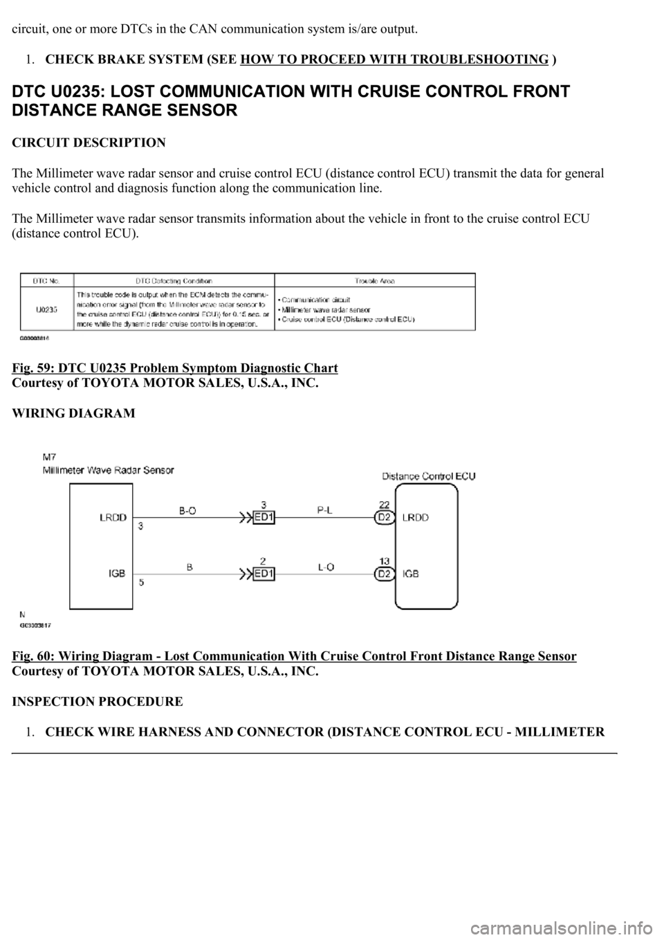
The Millimeter wave radar sensor and cruise control ECU (distance control ECU) transmit the data for general
vehicle control and diagnosis function along the communication line.
The Millimeter wave radar sensor transmits information about the vehicle in front to the cruise control ECU
(distance control ECU).
Fig. 59: DTC U0235 Problem Symptom Diagnostic Chart
Courtesy of TOYOTA MOTOR SALES, U.S.A., INC.
WIRING DIAGRAM
Fig. 60: Wiring Diagram
- Lost Communication With Cruise Control Front Distance Range Sensor
Courtesy of TOYOTA MOTOR SALES, U.S.A., INC.
INSPECTION PROCEDURE
1.CHECK WIRE HARNESS AND CONNECTOR (DISTANCE CONTROL ECU - MILLIMETER
Page 2634 of 4500
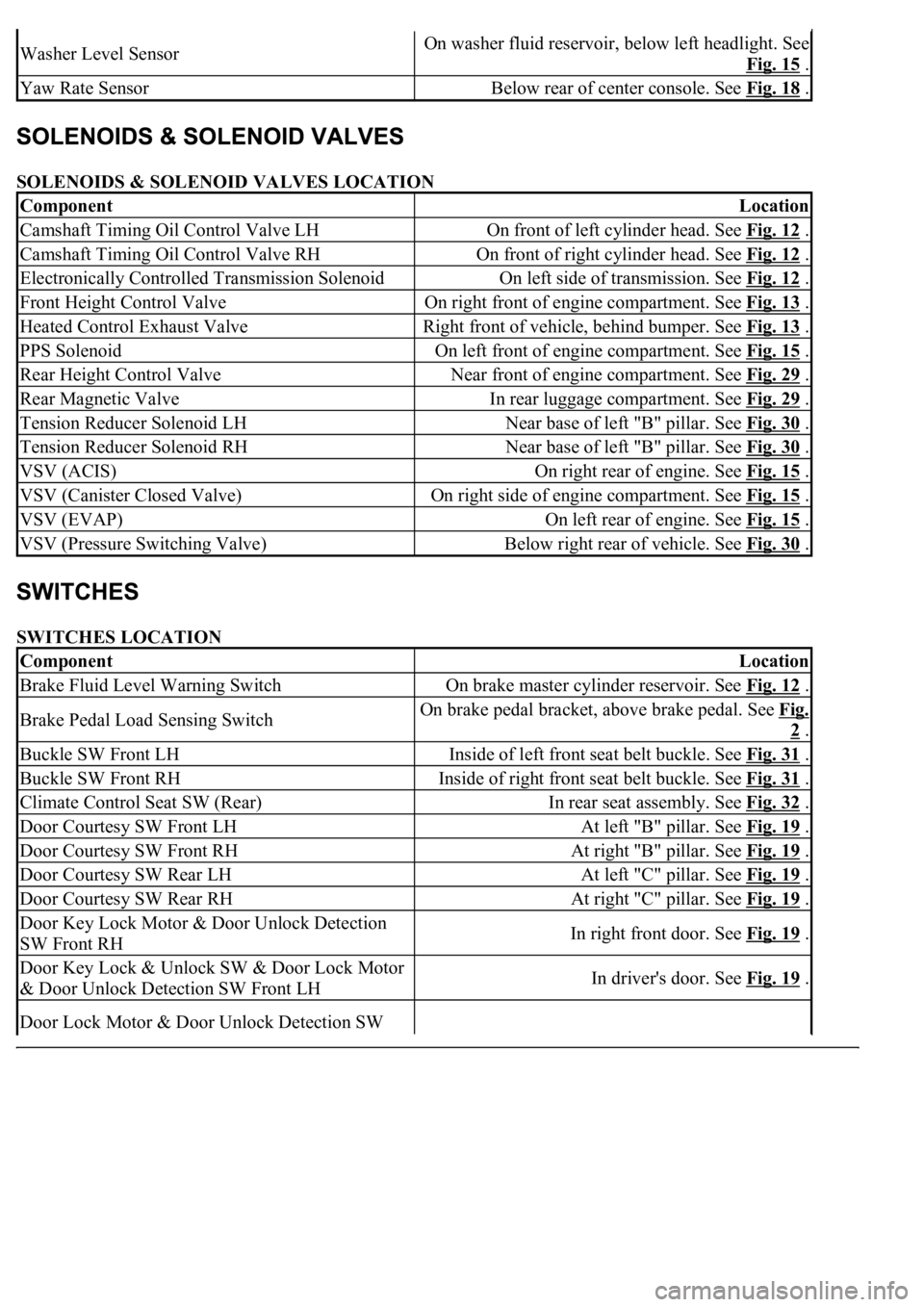
SOLENOIDS & SOLENOID VALVES LOCATION
SWITCHES LOCATION
Washer Level SensorOn washer fluid reservoir, below left headlight. See
Fig. 15
.
Yaw Rate SensorBelow rear of center console. See Fig. 18 .
ComponentLocation
Camshaft Timing Oil Control Valve LHOn front of left cylinder head. See Fig. 12 .
Camshaft Timing Oil Control Valve RHOn front of right cylinder head. See Fig. 12 .
Electronically Controlled Transmission SolenoidOn left side of transmission. See Fig. 12 .
Front Height Control ValveOn right front of engine compartment. See Fig. 13 .
Heated Control Exhaust ValveRight front of vehicle, behind bumper. See Fig. 13 .
PPS SolenoidOn left front of engine compartment. See Fig. 15 .
Rear Height Control ValveNear front of engine compartment. See Fig. 29 .
Rear Magnetic ValveIn rear luggage compartment. See Fig. 29 .
Tension Reducer Solenoid LHNear base of left "B" pillar. See Fig. 30 .
Tension Reducer Solenoid RHNear base of left "B" pillar. See Fig. 30 .
VSV (ACIS)On right rear of engine. See Fig. 15 .
VSV (Canister Closed Valve)On right side of engine compartment. See Fig. 15 .
VSV (EVAP)On left rear of engine. See Fig. 15 .
VSV (Pressure Switching Valve)Below right rear of vehicle. See Fig. 30 .
ComponentLocation
Brake Fluid Level Warning SwitchOn brake master cylinder reservoir. See Fig. 12 .
Brake Pedal Load Sensing SwitchOn brake pedal bracket, above brake pedal. See Fig.
2 .
Buckle SW Front LHInside of left front seat belt buckle. See Fig. 31 .
Buckle SW Front RHInside of right front seat belt buckle. See Fig. 31 .
Climate Control Seat SW (Rear)In rear seat assembly. See Fig. 32 .
Door Courtesy SW Front LHAt left "B" pillar. See Fig. 19 .
Door Courtesy SW Front RHAt right "B" pillar. See Fig. 19 .
Door Courtesy SW Rear LHAt left "C" pillar. See Fig. 19 .
Door Courtesy SW Rear RHAt right "C" pillar. See Fig. 19 .
Door Key Lock Motor & Door Unlock Detection
SW Front RHIn right front door. See Fig. 19 .
Door Key Lock & Unlock SW & Door Lock Motor
& Door Unlock Detection SW Front LHIn driver's door. See Fig. 19 .
Door Lock Motor & Door Unlock Detection SW