Page 1905 of 4500

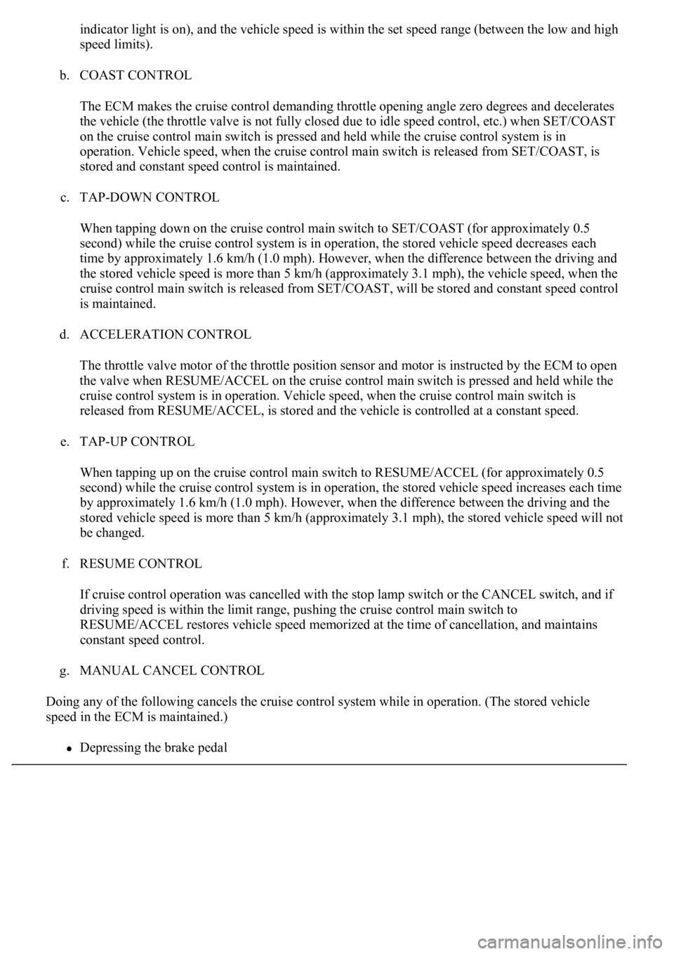
indicator light is on), and the vehicle speed is within the set speed range (between the low and high
speed limits).
b. COAST CONTROL
The ECM makes the cruise control demanding throttle opening angle zero degrees and decelerates
the vehicle (the throttle valve is not fully closed due to idle speed control, etc.) when SET/COAST
on the cruise control main switch is pressed and held while the cruise control system is in
operation. Vehicle speed, when the cruise control main switch is released from SET/COAST, is
stored and constant speed control is maintained.
c. TAP-DOWN CONTROL
When tapping down on the cruise control main switch to SET/COAST (for approximately 0.5
second) while the cruise control system is in operation, the stored vehicle speed decreases each
time by approximately 1.6 km/h (1.0 mph). However, when the difference between the driving and
the stored vehicle speed is more than 5 km/h (approximately 3.1 mph), the vehicle speed, when the
cruise control main switch is released from SET/COAST, will be stored and constant speed control
is maintained.
d. ACCELERATION CONTROL
The throttle valve motor of the throttle position sensor and motor is instructed by the ECM to open
<0057004b0048000300590044004f005900480003005a004b00480051000300350028003600380030002800120024002600260028002f00030052005100030057004b00480003004600550058004c005600480003004600520051005700550052004f000300
500044004c005100030056005a004c00570046004b0003004c[s pressed and held while the
cruise control system is in operation. Vehicle speed, when the cruise control main switch is
released from RESUME/ACCEL, is stored and the vehicle is controlled at a constant speed.
e. TAP-UP CONTROL
When tapping up on the cruise control main switch to RESUME/ACCEL (for approximately 0.5
second) while the cruise control system is in operation, the stored vehicle speed increases each time
by approximately 1.6 km/h (1.0 mph). However, when the difference between the driving and the
stored vehicle speed is more than 5 km/h (approximately 3.1 mph), the stored vehicle speed will not
be changed.
f. RESUME CONTROL
If cruise control operation was cancelled with the stop lamp switch or the CANCEL switch, and if
driving speed is within the limit range, pushing the cruise control main switch to
RESUME/ACCEL restores vehicle speed memorized at the time of cancellation, and maintains
constant speed control.
g. MANUAL CANCEL CONTROL
Doing any of the following cancels the cruise control system while in operation. (The stored vehicle
speed in the ECM is maintained.)
Depressing the brake pedal
Page 1948 of 4500
3. With the brake pedal depressed, push the cruise control main switch to RES/ACC 3 times within 3
seconds. Check that the VSC buzzer sounds at this time.
REPLACEMENT
1.SEPARATE BATTERY NEGATIVE TERMINAL
2.REMOVE ENGINE UNDER COVER NO. 1 (See REPLACEMENT
)
3.REMOVE FRONT WHEEL OPENING EXTENSION PAD LH (See REPLACEMENT
)
4.REMOVE FRONT FENDER LINER LH (See REPLACEMENT
)
5.REMOVE FRONT WHEEL OPENING EXTENSION PAD RH (See REPLACEMENT
)
6.REMOVE FRONT FENDER LINER RH (See REPLACEMENT
)
7.REMOVE FRONT BUMPER COVER (See step 5 in REPLACEMENT
)
8.REMOVE FRONT BUMPER REINFORCEMENT SUB-ASSY (See step 9 in REPLACEMENT
)
9.REMOVE LASER SENSOR
a. Disconnect the connector and remove the laser sensor.
Page 2033 of 4500

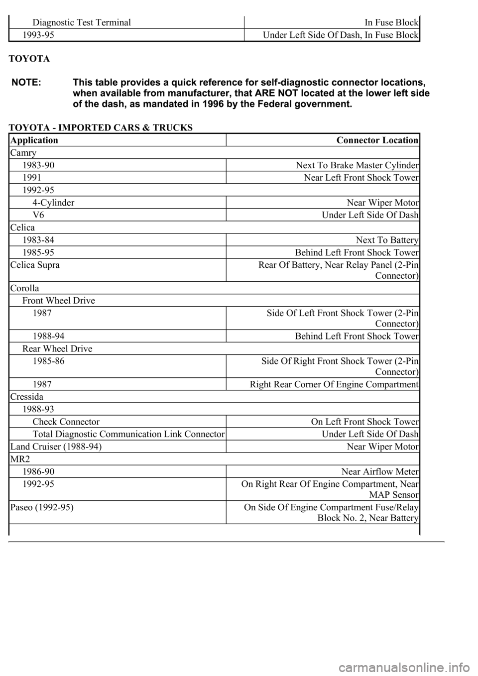
TOYOTA
TOYOTA - IMPORTED CARS & TRUCKS
Diagnostic Test TerminalIn Fuse Block
1993-95Under Left Side Of Dash, In Fuse Block
ApplicationConnector Location
Camry
1983-90Next To Brake Master Cylinder
1991Near Left Front Shock Tower
1992-95
4-CylinderNear Wiper Motor
V6Under Left Side Of Dash
Celica
1983-84Next To Battery
1985-95Behind Left Front Shock Tower
Celica SupraRear Of Battery, Near Relay Panel (2-Pin
Connector)
Corolla
Front Wheel Drive
1987Side Of Left Front Shock Tower (2-Pin
Connector)
1988-94Behind Left Front Shock Tower
Rear Wheel Drive
1985-86Side Of Right Front Shock Tower (2-Pin
Connector)
1987Right Rear Corner Of Engine Compartment
Cressida
1988-93
Check ConnectorOn Left Front Shock Tower
Total Diagnostic Communication Link ConnectorUnder Left Side Of Dash
Land Cruiser (1988-94)Near Wiper Motor
MR2
1986-90Near Airflow Meter
1992-95On Right Rear Of Engine Compartment, Near
MAP Sensor
Paseo (1992-95)On Side Of Engine Compartment Fuse/Relay
Block No. 2, Near Battery
Page 2356 of 4500
Fig. 51: Installing Disc Brake Caliper Bolts
Courtesy of TOYOTA MOTOR SALES, U.S.A., INC.
13.INSTALL SKID CONTROL SENSOR WIRE
a. Connect the connector.
14.INSTALL FRONT WHEELS
Torque: 103 N.m (1,050 kgf.cm, 76 ft.lbf)
15.INSPECT AND ADJUST FRONT WHEEL ALIGNMENT (See ADJUSTMENT
)
16.CHECK ABS SPEED SENSOR SIGNAL (See TEST MODE PROCEDURE
)
REPLACEMENT
HINT:
Page 2357 of 4500
See COMPONENTS
Use the same procedures for the RH side and LH side.
The procedures listed below are for the LH side.
1.REMOVE FRONT WHEELS
2.REMOVE FRONT DISC BRAKE CALIPER ASSY LH (See REPLACEMENT
)
3.REMOVE FRONT DISC (See OVERHAUL
)
4.SEPARATE SKID CONTROL SENSOR WIRE
a. Remove the bolt and separate the speed sensor from the steering knuckle.
b. Disconnect the connector.
Page 2362 of 4500
Fig. 56: Installing Skid Control Sensor Wire
Courtesy of TOYOTA MOTOR SALES, U.S.A., INC.
10.INSTALL FRONT DISC (See step 15 on OVERHAUL
)
11.INSTALL FRONT DISC BRAKE CALIPER ASSY LH (See REPLACEMENT
)
12.INSTALL FRONT WHEELS
Torque: 103 N.m (1,050 kgf.cm, 76 ft.lbf)
13.INSPECT AND ADJUST FRONT WHEEL ALIGNMENT (See ADJUSTMENT
)
14.CHECK ABS SPEED SENSOR SIGNAL (See TEST MODE PROCEDURE
)
Page 2371 of 4500
Fig. 65: Removing Speed Sensor Rear LH Bolt
Courtesy of TOYOTA MOTOR SALES, U.S.A., INC.
9.REMOVE REAR DISC BRAKE CALIPER ASSY LH
a. Remove the 2 bolts and separate the rear brake caliper from the rear axle carrier.
Page 2384 of 4500
Fig. 78: Installing Rear Disc Brake Caliper Assy LH Bolts
Courtesy of TOYOTA MOTOR SALES, U.S.A., INC.
26.INSTALL SPEED SENSOR REAR LH
a. Install the speed sensor to the rear axle carrier with the bolt.
Torque: 8.0 N.m (82 kgf.cm, 71 in.lbf)