Page 1734 of 4500
Courtesy of TOYOTA MOTOR SALES, U.S.A., INC.
p.INSPECT REAR SEATBACK HEATER ASSY RH
a. Measure the resistance between the terminals of the rear seatback heater RH.
Standard:
TESTER CONNECTION AND SPECIFIED CONDITION
If the result is not as specified, replace the rear seatback heater assy RH.
Fig. 100: Identifying Rear Seatback Heater RH Connector Terminals
Courtesy of TOYOTA MOTOR SALES, U.S.A., INC.
Tester ConnectionConditionSpecified Condition
A2 - A420°C (68°F)5.4 to 6.6 ohms
S61-4 - A220°C (68°F)5.4 to 6.6 ohms
S61-2 - A420°C (68°F)5.4 to 6.6 ohms
S61-1 - A1AlwaysBelow 1 ohms
S61-3 - A3AlwaysBelow 1 ohms
Page 1737 of 4500
Fig. 2: Identifying Components Locations (1 Of 3)
Courtesy of TOYOTA MOTOR SALES, U.S.A., INC.
Page 1738 of 4500
Fig. 3: Identifying Components Locations (2 Of 3)
Courtesy of TOYOTA MOTOR SALES, U.S.A., INC.
Page 1739 of 4500
Fig. 4: Identifying Components Locations (3 Of 3)
Courtesy of TOYOTA MOTOR SALES, U.S.A., INC.
Page 1745 of 4500

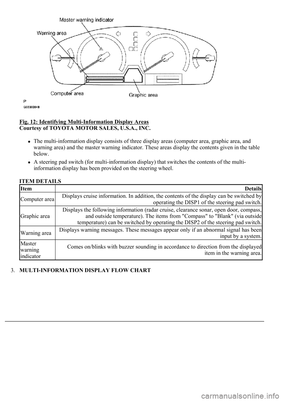
Fig. 12: Identifying Multi-Information Display Areas
Courtesy of TOYOTA MOTOR SALES, U.S.A., INC.
The multi-information display consists of three display areas (computer area, graphic area, and
warning area) and the master warning indicator. These areas display the contents given in the table
below.
A steering pad switch (for multi-information display) that switches the contents of the multi-
<004c0051004900520055005000440057004c0052005100030047004c00560053004f0044005c0003004b004400560003004500480048005100030053005500520059004c00470048004700030052005100030057004b004800030056005700480048005500
4c0051004a0003005a004b00480048004f001100030003[
ITEM DETAILS
3.MULTI-INFORMATION DISPLAY FLOW CHART
ItemDetails
Computer areaDisplays cruise information. In addition, the contents of the display can be switched by
operating the DISP1 of the steering pad switch.
Graphic area
Displays the following information (radar cruise, clearance sonar, open door, compass,
and outside temperature). The items from "Compass" to "Blank" (via outside
temperature) can be switched by operating the DISP2 of the steering pad switch.
Warning areaDisplays warning messages. These messages appear only if an abnormal signal has been
input by a system.
Master
warning
indicatorComes on/blinks with buzzer sounding in accordance to direction from the displayed
item in the warning area.
Page 1755 of 4500
Fig. 19: Identifying Zone Setting Number
Courtesy of TOYOTA MOTOR SALES, U.S.A., INC.
8.CALIBRATION SETTING MODE
a. Keep pressing the "RESET" for 6 sec. after selection of the compass display mode will activate the
calibration setting mode.
b. Drive the vehicle at a slow speed of 8 km/h (5 MPH) or less in the circular direction.
c. Driving round the circle 1 to 3 times will display the azimuthal direction on the display, completing
the calibration.
d. To finish the calibration mode, press the DISP2 switch long when the calibration is finished or
during the calibration.
HINT:
Page 1762 of 4500
Fig. 26: Identifying Terminals Of ECU (Combination Meter Assy)
Courtesy of TOYOTA MOTOR SALES, U.S.A., INC.
COMBINATION METER ASSY CONNECTOR TERMINALS REFERENCE
Symbols
(Terminals No.)Wiring
ColorTerminal DescriptionConditionSpecified
Condition
IG + (C12-1) -
Body groundY - Body
groundIgnition switch signal
(ON)Ignition switch OFF -->
ONBelow 1 V --> 10
to 14 V
MPX + (C12-2) -
Body groundGR-B -
Body groundMultiplex
communication signal--
MPX- (C12-3) -
Body groundGR-B -
Body groundMultiplex
communication signal--
S (C12-4) - Body
groundB-Y - Body
groundTachometer signalEngine runningPulse generation
(See waveform 1)
CHECK (C12-5) -
Body groundY-R - Body
groundCHECK ENGINE
signalCHECK ENGINE warning
light ON --> OFFBelow 1 V --> 10
to 14 V
TEMS (C12-6) -
Body groundY - Body
groundTEMS SPORT signalTEMS SPORT indicator
light ON --> OFFBelow 1 V --> 10
to 14 V
A/B (C12-7) - V-R (W) - ODO/TRIP signalIgnition switch ON,
ODO/TRIP switch ON -->
Below 1 V --> 4.5
Page 1764 of 4500
Fig. 27: Identifying Waveform 1
Courtesy of TOYOTA MOTOR SALES, U.S.A., INC.
Waveform 1 (Reference):
WAVEFORM 1 (REFERENCE)
ItemContents
Tool setting5V/DIV, 10 ms/DIV
Vehicle conditionEngine idle speed