Page 3416 of 4500
Fig. 135: Identifying Oil Pan Stud Bolt Diameter
Courtesy of TOYOTA MOTOR SALES, U.S.A., INC.
56.INSTALL OIL PAN SUB-ASSY (See REPLACEMENT
)
57.INSTALL OIL PAN BAFFLE PLATE (See REPLACEMENT
)
58.INSTALL OIL PAN SUB-ASSY NO.2 (See REPLACEMENT
)
59.INSTALL WATER PUMP ASSY
a. Install a new gasket and water pump with the 5 bolts, 2 stud bolts and nut. Uniformly tighten the
bolts, stud bolts and nut in several passes.
Torque:
21 N.m (214 kgf.cm, 16 ft.lbf) for bolt
18 N.m (184 kgf.cm, 13 ft.lbf) for stud bolt and nut
HINT:
Use bolts that are 30 mm (1.18 in.) in len
gth.
Page 3417 of 4500
Fig. 136: Identifying Water Pump Assy Bolts
Courtesy of TOYOTA MOTOR SALES, U.S.A., INC.
60.INSTALL CYLINDER HEAD SUB-ASSY
a. Place a new cylinder head gasket on the cylinder block.
HINT:
The rear side of the cylinder head gasket has marks so that the RH and LH banks can be
distinguished. A "3R" mark is on the RH bank's gasket.
b. Place the cylinder head on the cylinder head gasket.
Page 3453 of 4500
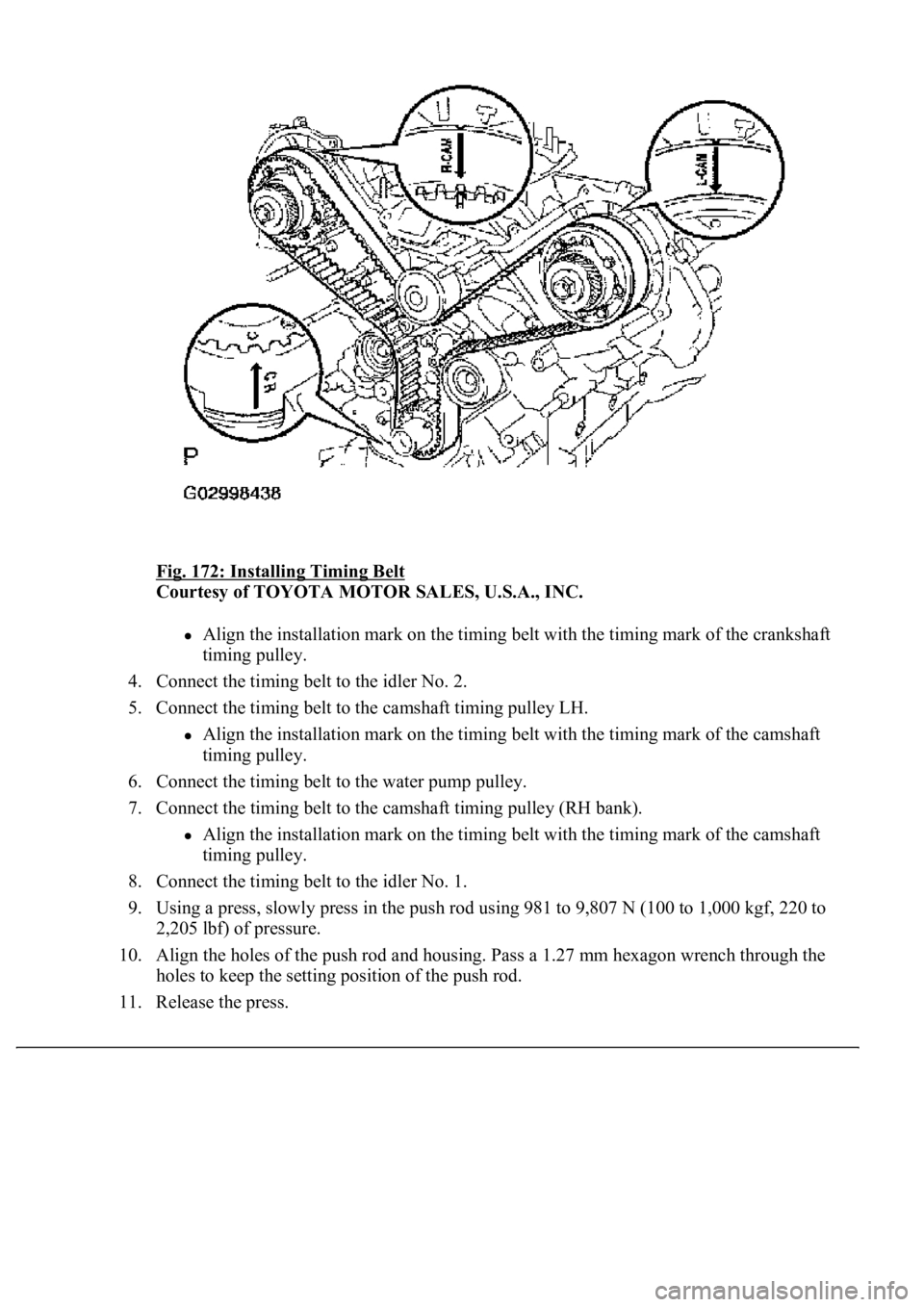
Fig. 172: Installing Timing Belt
Courtesy of TOYOTA MOTOR SALES, U.S.A., INC.
Align the installation mark on the timing belt with the timing mark of the crankshaft
timing pulley.
4. Connect the timing belt to the idler No. 2.
5. Connect the timing belt to the camshaft timing pulley LH.
Align the installation mark on the timing belt with the timing mark of the camshaft
timing pulley.
6. Connect the timing belt to the water pump pulley.
7. Connect the timing belt to the camshaft timing pulley (RH bank).
Align the installation mark on the timing belt with the timing mark of the camshaft
timing pulley.
8. Connect the timing belt to the idler No. 1.
9. Using a press, slowly press in the push rod using 981 to 9,807 N (100 to 1,000 kgf, 220 to
2,205 lbf) of pressure.
10. Align the holes of the push rod and housing. Pass a 1.27 mm hexagon wrench through the
<004b0052004f004800560003005700520003004e00480048005300030057004b004800030056004800570057004c0051004a0003005300520056004c0057004c0052005100030052004900030057004b00480003005300580056004b000300550052004700
1100030003[
11. Release the press.
Page 3478 of 4500
Fig. 195: Turning Camshaft Timing Pulley (RH Bank) Using SST
Courtesy of TOYOTA MOTOR SALES, U.S.A., INC.
e. Disconnect the belt from the timing belt idler No. 1, and remove the belt.
26.INSTALL TIMING BELT
a. Check the belt idler No. 1 and No. 2.
1. Visually check the seal portion of the idler pulley for oil leakage.
If leakage is found, replace the idler.
2. Check that the idler turns smoothly.
If necessary, replace the idler.
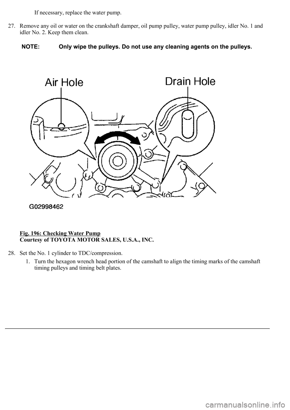
b. Check the water pump.
1. Visually check the air hole and water hole for coolant leakage.
If leakage is found, replace the water pump and belt.
2. Turn the pulle
y, and check that the water pump bearing moves smoothly and quietly.
Page 3479 of 4500
If necessary, replace the water pump.
27. Remove any oil or water on the crankshaft damper, oil pump pulley, water pump pulley, idler No. 1 and
idler No. 2. Keep them clean.
Fig. 196: Checking Water Pump
Courtesy of TOYOTA MOTOR SALES, U.S.A., INC.
28. Set the No. 1 cylinder to TDC/compression.
1. Turn the hexagon wrench head portion of the camshaft to align the timing marks of the camshaft
timing pulleys and timing belt plates.
Page 3482 of 4500
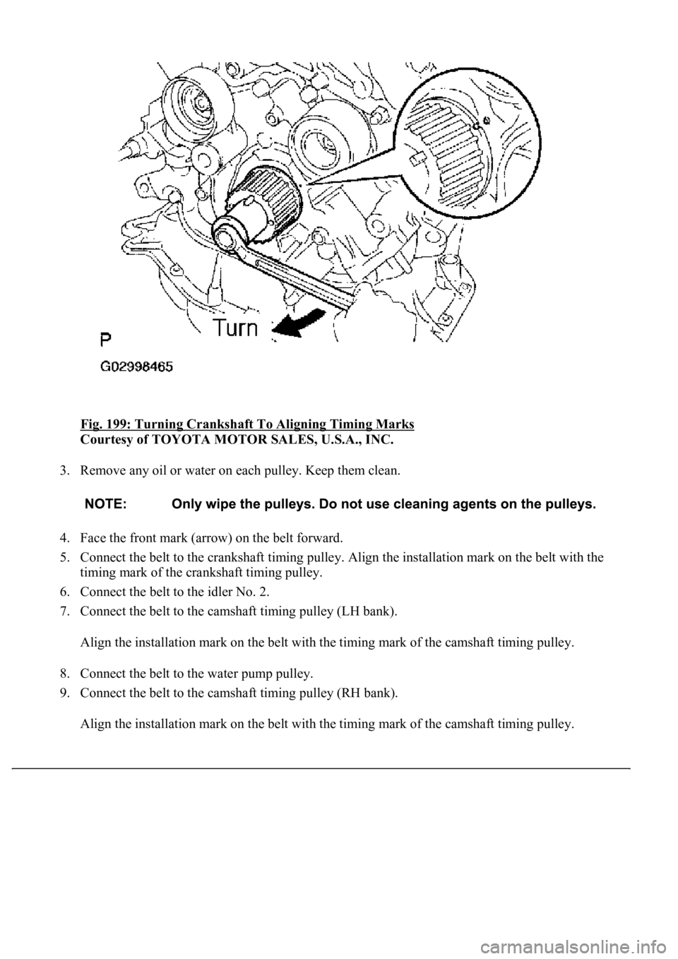
Fig. 199: Turning Crankshaft To Aligning Timing Marks
Courtesy of TOYOTA MOTOR SALES, U.S.A., INC.
3. Remove any oil or water on each pulley. Keep them clean.
4. Face the front mark (arrow) on the belt forward.
5. Connect the belt to the crankshaft timing pulley. Align the installation mark on the belt with the
timing mark of the crankshaft timing pulley.
6. Connect the belt to the idler No. 2.
7. Connect the belt to the camshaft timing pulley (LH bank).
Align the installation mark on the belt with the timing mark of the camshaft timing pulley.
8. Connect the belt to the water pump pulley.
9. Connect the belt to the camshaft timing pulley (RH bank).
Align the installation mark on the belt with the timing mark of the camshaft timing pulley.
Page 4412 of 4500
a. Install the cover bracket with the bolt.
Torque: 7.5 N.m (76 kgf.cm, 66 in.lbf)
23.INSTALL THROTTLE BODY ASSY
a. Install the throttle body with the 2 bolts and 2 nuts.
b. Connect the water by-pass hose.
c. Connect the PCV hose.
d. Connect the connector to the throttle body.
24.INSTALL INTAKE AIR CONNECTOR PIPE
a. Install the intake air connector pipe with the bolt and hose clamp.
Torque:
4.0 N.m (40 kgf.cm, 35 in.lbf) for hose clamp
5.0 N.m (50 kgf.cm, 44 in.lbf) for bolt
b. Connect the air hose and ventilation hose No. 1 together.
25.INSTALL AIR CLEANER INLET NO. 1
26.INSPECT FUEL PUMP OPERATION AND CHECK FOR FUEL LEAKS
27.INSTALL V-BANK COVER
a. Install the V-bank cover with the 2 nuts.
Torque: 5.0 N.m (50 kgf.cm, 44 in.lbf)
28.REFILL ENGINE COOLANT
29.CHECK FOR ENGINE COOLANT LEAKS
a. Check for engine coolant leaks.
If leaks are present, find the leak and repair or replace parts as necessar
y.
Page:
< prev 1-8 9-16 17-24