Page 706 of 4500

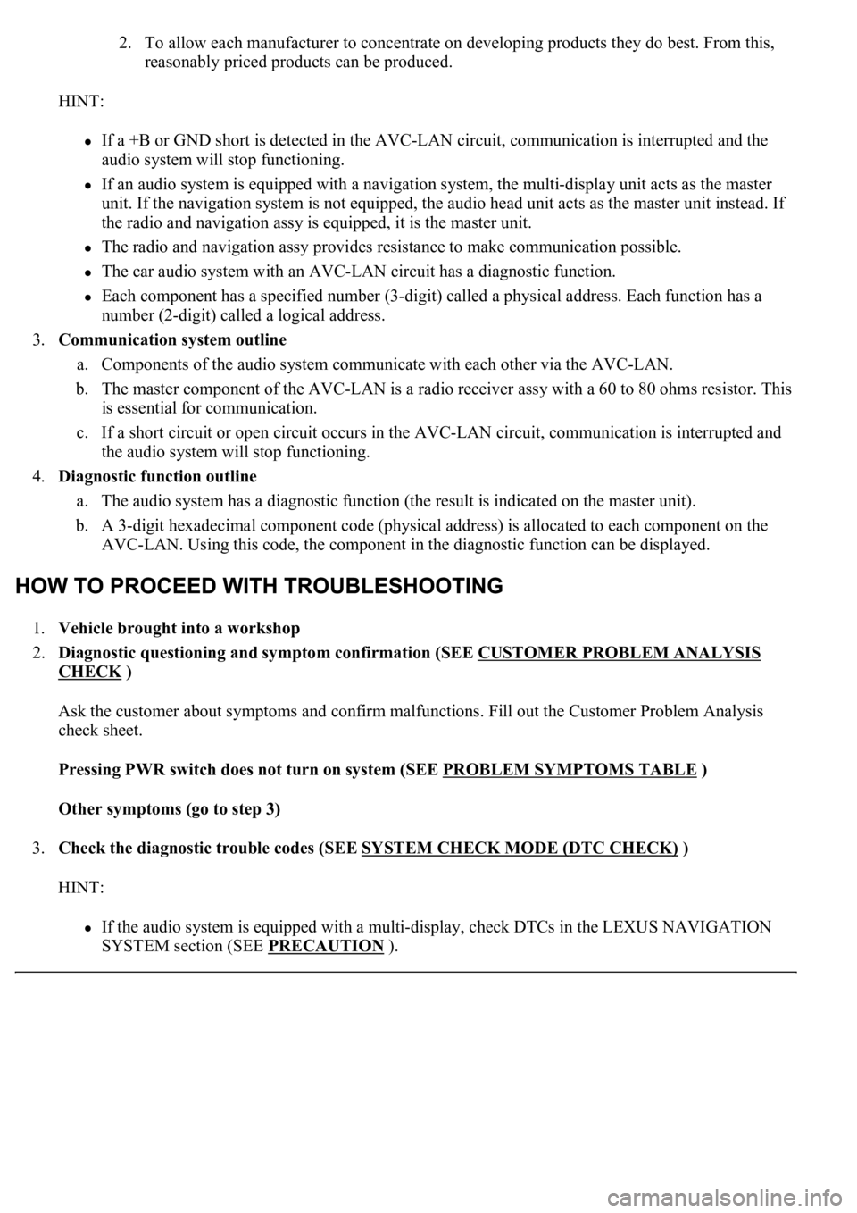
2. To allow each manufacturer to concentrate on developing products they do best. From this,
reasonably priced products can be produced.
HINT:
If a +B or GND short is detected in the AVC-LAN circuit, communication is interrupted and the
audio system will stop functioning.
If an audio system is equipped with a navigation system, the multi-display unit acts as the master
unit. If the navigation system is not equipped, the audio head unit acts as the master unit instead. If
the radio and navigation assy is equipped, it is the master unit.
The radio and navigation assy provides resistance to make communication possible.
The car audio system with an AVC-LAN circuit has a diagnostic function.
Each component has a specified number (3-digit) called a physical address. Each function has a
number (2-digit) called a logical address.
3.Communication system outline
a. Components of the audio system communicate with each other via the AVC-LAN.
b. The master component of the AVC-LAN is a radio receiver assy with a 60 to 80 ohms resistor. This
is essential for communication.
c. If a short circuit or open circuit occurs in the AVC-LAN circuit, communication is interrupted and
the audio system will stop functioning.
4.Diagnostic function outline
a. The audio system has a diagnostic function (the result is indicated on the master unit).
b. A 3-digit hexadecimal component code (physical address) is allocated to each component on the
AVC-LAN. Using this code, the component in the diagnostic function can be displayed.
1.Vehicle brought into a workshop
2.Diagnostic questioning and symptom confirmation (SEE CUSTOMER PROBLEM ANALYSIS
CHECK )
Ask the customer about symptoms and confirm malfunctions. Fill out the Customer Problem Analysis
check sheet.
Pressing PWR switch does not turn on system (SEE PROBLEM SYMPTOMS TABLE
)
Other symptoms (go to step 3)
3.Check the diagnostic trouble codes (SEE SYSTEM CHECK MODE (DTC CHECK)
)
HINT:
If the audio system is equipped with a multi-display, check DTCs in the LEXUS NAVIGATION
SYSTEM section (SEE PRECAUTION
).
Page 719 of 4500

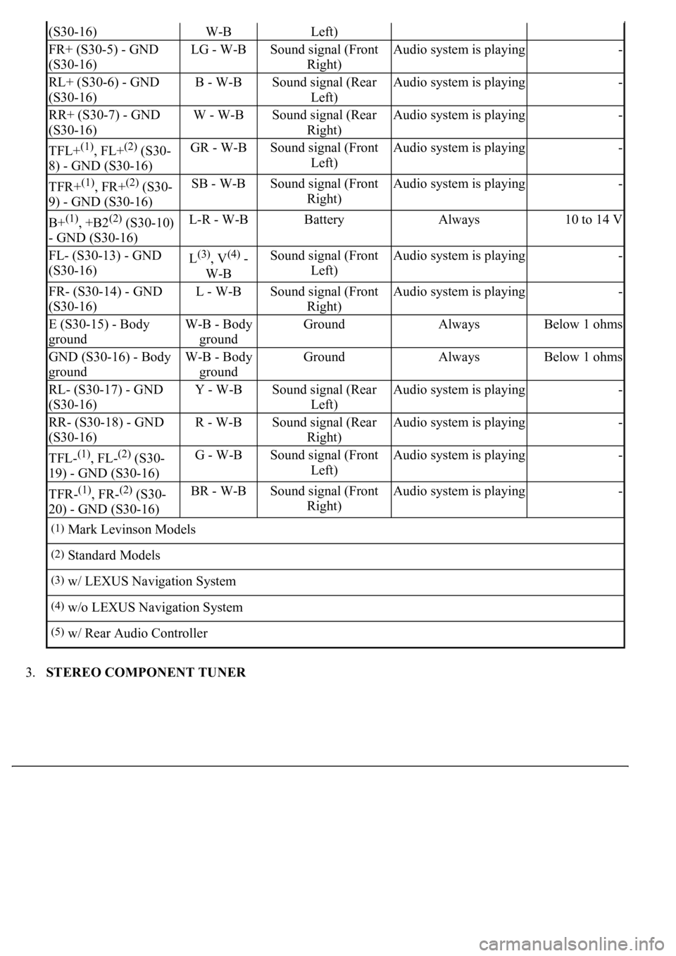
3.STEREO COMPONENT TUNER
(S30-16)W-BLeft)
FR+ (S30-5) - GND
(S30-16)LG - W-BSound signal (Front
Right)Audio system is playing-
RL+ (S30-6) - GND
(S30-16)B - W-BSound signal (Rear
Left)Audio system is playing-
RR+ (S30-7) - GND
(S30-16)W - W-BSound signal (Rear
Right)Audio system is playing-
TFL+(1), FL+(2) (S30-
8) - GND (S30-16)GR - W-BSound signal (Front
Left)Audio system is playing-
TFR+(1), FR+(2) (S30-
9) - GND (S30-16)SB - W-BSound signal (Front
Right)Audio system is playing-
B+(1), +B2(2) (S30-10)
- GND (S30-16)L-R - W-BBatteryAlways10 to 14 V
FL- (S30-13) - GND
(S30-16)L(3), V(4) -
W-BSound signal (Front
Left)Audio system is playing-
FR- (S30-14) - GND
(S30-16)L - W-BSound signal (Front
Right)Audio system is playing-
E (S30-15) - Body
groundW-B - Body
groundGroundAlwaysBelow 1 ohms
GND (S30-16) - Body
groundW-B - Body
groundGroundAlwaysBelow 1 ohms
RL- (S30-17) - GND
(S30-16)Y - W-BSound signal (Rear
Left)Audio system is playing-
RR- (S30-18) - GND
(S30-16)R - W-BSound signal (Rear
Right)Audio system is playing-
TFL-(1), FL-(2) (S30-
19) - GND (S30-16)G - W-BSound signal (Front
Left)Audio system is playing-
TFR-(1), FR-(2) (S30-
20) - GND (S30-16)BR - W-BSound signal (Front
Right)Audio system is playing-
(1)Mark Levinson Models
(2)Standard Models
(3)w/ LEXUS Navigation System
(4)w/o LEXUS Navigation System
(5)w/ Rear Audio Controller
Page 721 of 4500
4.AUDIO AND REAR A/C CONTROL SW
Fig. 17: Audio And Rear A/C Control SW ECU Terminal Connector
Courtesy of TOYOTA MOTOR SALES, U.S.A., INC.
TERMINAL DESCRIPTION CHART
ATX- (S31-20) -
GND (S31-25)R - W-BAVC-LAN
communication signalTurn ignition switch to
ACC2 to 3 V
MTX- (S31-21) -
GND (S31-25)B - W-BAVC-LAN
communication signalTurn ignition switch to
ACC2 to 3 V
GND (S31-25) -
Body groundW-B - Body
groundGroundAlwaysBelow 1 ohms
(1)w/ LEXUS Navigation System
Symbols (Terminal
No.)Wiring
ColorTerminal DescriptionConditionSpecification
Page 790 of 4500
Fig. 72: Identifying Blinking Pattern
Courtesy of TOYOTA MOTOR SALES, U.S.A., INC.
NG: GO TO COMBINATION METER SYSTEM (SEE PRECAUTION
)
OK: PROCEED TO NEXT CIRCUIT INSPECTION SHOWN ON PROBLEM SYMPTOMS
TABLE
CIRCUIT DESCRIPTION
This circuit sends the signal to the stereo component amplifier to mute the noise. Because of that, the noise
produced by changing the sound source ceases.
In addition, this circuit is used to mute the sound when the navigation system performs voice guide.
If there is an open in the circuit, noise can be heard from the speaker when changing the sound source.
When the vehicle is equipped with the navigation system, audio sound keeps coming out from the speaker on
the driver's side while the voice navigation is in operation.
If there is a short in the circuit, even though the stereo component amplifier assy is normal, no sound or only
extremely small sound can be produced.
WIRING DIAGRAM
Page 796 of 4500
Fig. 78: Identifying Stereo Connector Amplifier Connector
Courtesy of TOYOTA MOTOR SALES, U.S.A., INC.
CIRCUIT DESCRIPTION
This circuit sends the signal to the stereo component amplifier to mute the noise. Because of that, the noise
produced by changing the sound source ceases.
In addition, this circuit is used to mute the sound when the navigation system performs voice guide.
If there is an open in the circuit, noise can be heard from the speaker when changing the sound source.
When the vehicle is equipped with the navigation system, audio sound keeps coming out from the speaker on
the driver's side while the voice navigation is in operation.
If there is a short in the circuit, even though the stereo component amplifier assy is normal, no sound or only
extremel
y small sound can be produced.
Page 1197 of 4500
Fig. 7: Wiring Diagram - Can Communication System (W/LEXUS Navigation System)
Courtesy of TOYOTA MOTOR SALES, U.S.A., INC.
Page 1198 of 4500
Fig. 8: Wiring Diagram - Can Communication System (W/O LEXUS Navigation System)
Courtesy of TOYOTA MOTOR SALES, U.S.A., INC.
HINT:
The position of the terminus circuit differs in vehicles with and without the LEXUS navigation system.
The skid control ECU with actuator detects and stores steering sensor and yaw rate sensor DTCs and
performs DTC communication by receiving information from the steering sensor and yaw rate sensor.
The ECM detects and stores distance control ECU DTCs, and performs DTC communication by
receiving information from the distance control ECU.
The ECM uses the CAN communication system to perform DTC communication instead of the
Page 1200 of 4500

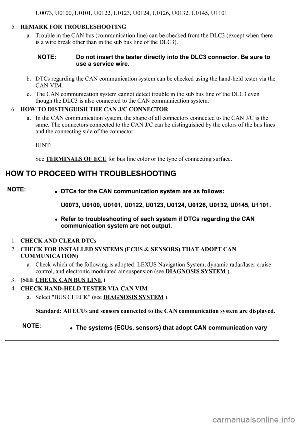
U0073, U0100, U0101, U0122, U0123, U0124, U0126, U0132, U0145, U1101
5.REMARK FOR TROUBLESHOOTING
a. Trouble in the CAN bus (communication line) can be checked from the DLC3 (except when there
is a wire break other than in the sub bus line of the DLC3).
b. DTCs regarding the CAN communication system can be checked using the hand-held tester via the
CAN VIM.
c. The CAN communication system cannot detect trouble in the sub bus line of the DLC3 even
though the DLC3 is also connected to the CAN communication system.
6.HOW TO DISTINGUISH THE CAN J/C CONNECTOR
a. In the CAN communication system, the shape of all connectors connected to the CAN J/C is the
same. The connectors connected to the CAN J/C can be distinguished by the colors of the bus lines
and the connecting side of the connector.
HINT:
See TERMINALS OF ECU
for bus line color or the type of connecting surface.
1.CHECK AND CLEAR DTCs
2.CHECK FOR INSTALLED SYSTEMS (ECUS & SENSORS) THAT ADOPT CAN
COMMUNICATION)
a. Check which of the following is adopted: LEXUS Navigation System, dynamic radar/laser cruise
control, and electronic modulated air suspension (see DIAGNOSIS SYSTEM
).
3.(SEE CHECK CAN BUS LINE
)
4.CHECK HAND-HELD TESTER VIA CAN VIM
a. Select "BUS CHECK" (see DIAGNOSIS SYSTEM
).
Standard: All ECUs and sensors connected to the CAN communication system are displayed.