Page 901 of 4500
Fig. 80: Removing Check Ball Body And Spring
Courtesy of TOYOTA MOTOR SALES, U.S.A., INC.
c. Remove the bolt, lock plate and lock up control solenoid (SLU) and clutch control solenoid (SL2).
d. Remove the bolt and automatic transmission 3-way solenoid assy (S3).
e. Remove the bolt and automatic transmission 3-way solenoid (S2) and automatic transmission 3-
way solenoid (S4).
f. Remove the bolt and automatic transmission 3-way solenoid (S1).
g. Remove the bolt and automatic transmission 3-way solenoid (SR).
h. Remove the bolt, lock plate and clutch control solenoid No.1 (SL1) and line pressure control
solenoid (SLT).
Page 903 of 4500
7.INSTALL TRANSMISSION VALVE BODY ASSY
a. Install the clutch control solenoid No.1 (SL1) and line pressure control solenoid (SLT) with the
lock plate and bolt.
Torque: 6.4 N.m (65 kgf.cm, 56 in..lbf)
b. Install the automatic transmission 3-way solenoid (SR) with the bolt.
Torque: 10 N.m (100 kgf.cm, 7 ft.lbf)
c. Install the automatic transmission 3-way solenoid (S1) with the bolt.
Torque: 10 N.m (100 kgf.cm, 7 ft.lbf)
d. Install the automatic transmission 3-way solenoid (S2) and automatic transmission 3-way solenoid
(S4) with the bolt.
Torque: 10 N.m (100 kgf.cm, 7 ft.lbf)
e. Install the automatic transmission 3-way solenoid (S3) with the bolt.
Torque: 10 N.m (100 kgf.cm, 7 ft.lbf)
f. Install the lock up control solenoid (SLU) and clutch control solenoid (SL2) with the lock plate and
bolt.
Torque: 6.4 N.m (65 kgf.cm, 56 in..lbf)
Page 2415 of 4500

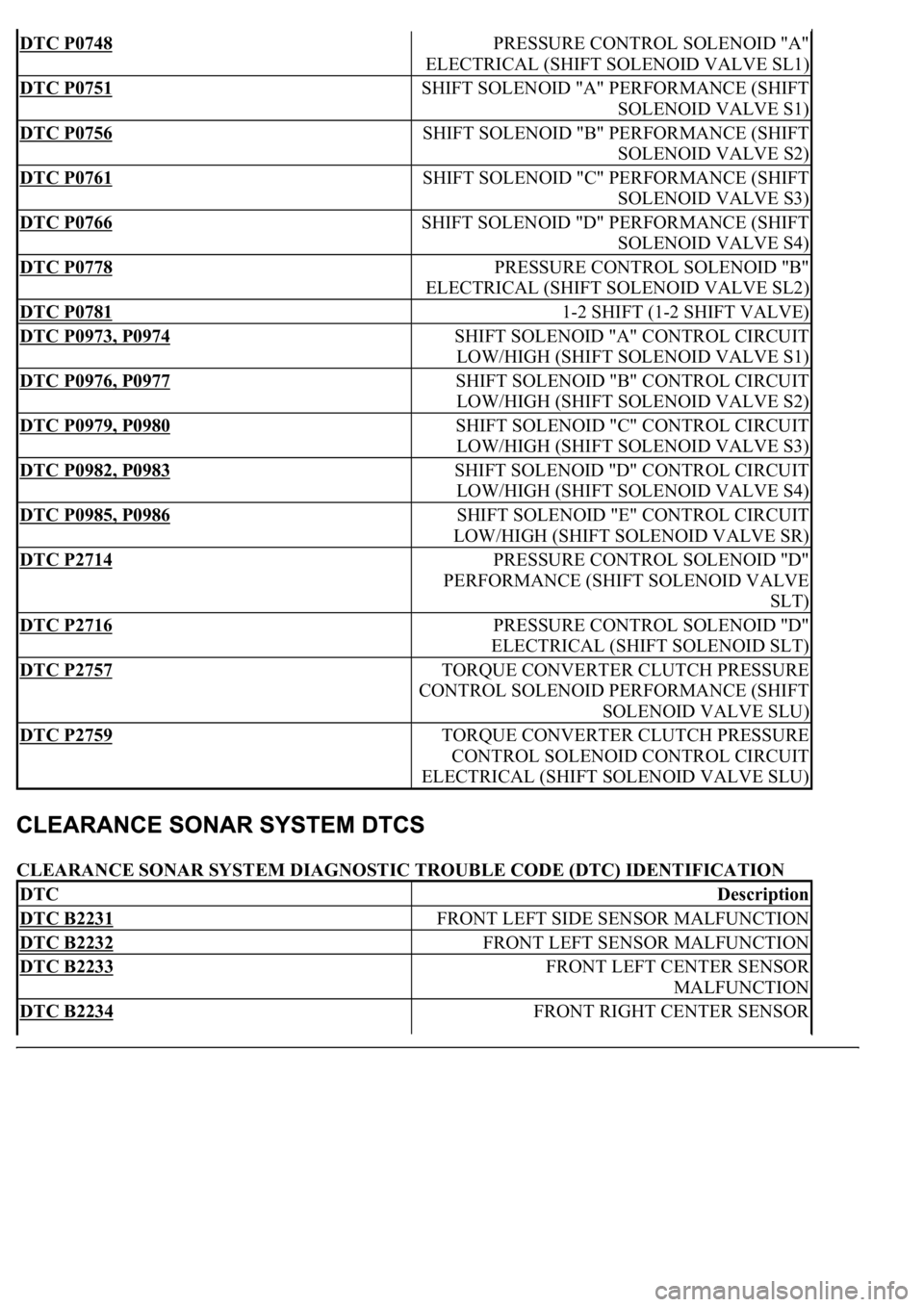
CLEARANCE SONAR SYSTEM DIAGNOSTIC TROUBLE CODE (DTC) IDENTIFICATION
DTC P0748 PRESSURE CONTROL SOLENOID "A"
ELECTRICAL (SHIFT SOLENOID VALVE SL1)
DTC P0751 SHIFT SOLENOID "A" PERFORMANCE (SHIFT
SOLENOID VALVE S1)
DTC P0756 SHIFT SOLENOID "B" PERFORMANCE (SHIFT
SOLENOID VALVE S2)
DTC P0761 SHIFT SOLENOID "C" PERFORMANCE (SHIFT
SOLENOID VALVE S3)
DTC P0766 SHIFT SOLENOID "D" PERFORMANCE (SHIFT
SOLENOID VALVE S4)
DTC P0778 PRESSURE CONTROL SOLENOID "B"
ELECTRICAL (SHIFT SOLENOID VALVE SL2)
DTC P0781 1-2 SHIFT (1-2 SHIFT VALVE)
DTC P0973, P0974 SHIFT SOLENOID "A" CONTROL CIRCUIT
LOW/HIGH (SHIFT SOLENOID VALVE S1)
DTC P0976, P0977 SHIFT SOLENOID "B" CONTROL CIRCUIT
LOW/HIGH (SHIFT SOLENOID VALVE S2)
DTC P0979, P0980 SHIFT SOLENOID "C" CONTROL CIRCUIT
LOW/HIGH (SHIFT SOLENOID VALVE S3)
DTC P0982, P0983 SHIFT SOLENOID "D" CONTROL CIRCUIT
LOW/HIGH (SHIFT SOLENOID VALVE S4)
DTC P0985, P0986 SHIFT SOLENOID "E" CONTROL CIRCUIT
LOW/HIGH (SHIFT SOLENOID VALVE SR)
DTC P2714 PRESSURE CONTROL SOLENOID "D"
PERFORMANCE (SHIFT SOLENOID VALVE
SLT)
DTC P2716 PRESSURE CONTROL SOLENOID "D"
ELECTRICAL (SHIFT SOLENOID SLT)
DTC P2757 TORQUE CONVERTER CLUTCH PRESSURE
CONTROL SOLENOID PERFORMANCE (SHIFT
SOLENOID VALVE SLU)
DTC P2759 TORQUE CONVERTER CLUTCH PRESSURE
CONTROL SOLENOID CONTROL CIRCUIT
ELECTRICAL (SHIFT SOLENOID VALVE SLU)
DTCDescription
DTC B2231 FRONT LEFT SIDE SENSOR MALFUNCTION
DTC B2232 FRONT LEFT SENSOR MALFUNCTION
DTC B2233 FRONT LEFT CENTER SENSOR
MALFUNCTION
DTC B2234 FRONT RIGHT CENTER SENSOR
Page 2679 of 4500

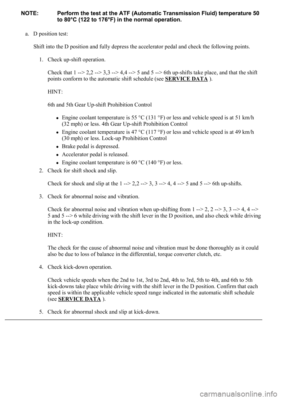
a. D position test:
Shift into the D position and fully depress the accelerator pedal and check the following points.
1. Check up-shift operation.
Check that 1 --> 2,2 --> 3,3 --> 4,4 --> 5 and 5 --> 6th up-shifts take place, and that the shift
points conform to the automatic shift schedule (see SERVICE DATA
).
HINT:
6th and 5th Gear Up-shift Prohibition Control
Engine coolant temperature is 55 °C (131 °F) or less and vehicle speed is at 51 km/h
(32 mph) or less. 4th Gear Up-shift Prohibition Control
Engine coolant temperature is 47 °C (117 °F) or less and vehicle speed is at 49 km/h
(30 mph) or less. Lock-up Prohibition Control
Brake pedal is depressed.
Accelerator pedal is released.
<00280051004a004c005100480003004600520052004f0044005100570003005700480050005300480055004400570058005500480003004c00560003001900130003008300260003000b001400170013000300830029000c0003005200550003004f004800
560056001100030003[
2. Check for shift shock and slip.
Check for shock and slip at the 1 --> 2,2 --> 3, 3 --> 4, 4 --> 5 and 5 --> 6th up-shifts.
3. Check for abnormal noise and vibration.
Check for abnormal noise and vibration when up-shifting from 1 --> 2, 2 --> 3, 3 --> 4, 4 -->
5 and 5 --> 6 while driving with the shift lever in the D position, and also check while driving
in the lock-up condition.
HINT:
The check for the cause of abnormal noise and vibration must be done thoroughly as it could
also be due to loss of balance in the differential, torque converter clutch, etc.
4. Check kick-down operation.
<0026004b00480046004e000300590048004b004c0046004f004800030056005300480048004700560003005a004b0048005100030057004b004800030015005100470003005700520003001400560057000f00030016005500470003005700520003001500
510047000f000300170057004b000300570052000300160055[d, 5th to 4th, and 6th to 5th
kick-downs take place while driving with the shift lever in the D position. Confirm that each
speed is within the applicable vehicle speed range indicated in the automatic shift schedule
(see SERVICE DATA
).
5. Check for abnormal shock and slip at kic
k-down.
Page 2682 of 4500
Fig. 7: Mechanical Systems Problem Symptoms Chart
Courtesy of TOYOTA MOTOR SALES, U.S.A., INC.
b. Measure the time lag.
1. When the shift lever is shifted while the engine is idling, there will be a certain time lapse or
lag before the shock can be felt. This is used for checking the condition of the direct clutch,
forward clutch, and 1st and reverse brake.
2. Connect an OBD II scan tool or hand-held tester to the DLC3.
3. Fully apply the parking brake.
4. Start and warm up the engine and check idle speed.
Idle speed: approx. 700 rpm (In N position and A/C OFF)
5. Shift the lever from N to D position. Using a stop watch, measure the time from when the
lever is shifted until the shock is felt.
Time lag: N --> D less than 1.2 seconds
6. In the same way, measure the time lag for N --> R.
Time lag: N --> R less than 1.5 seconds
Evaluation (If N --> D or N --> R time lag is longer than the specified):
Page 2726 of 4500

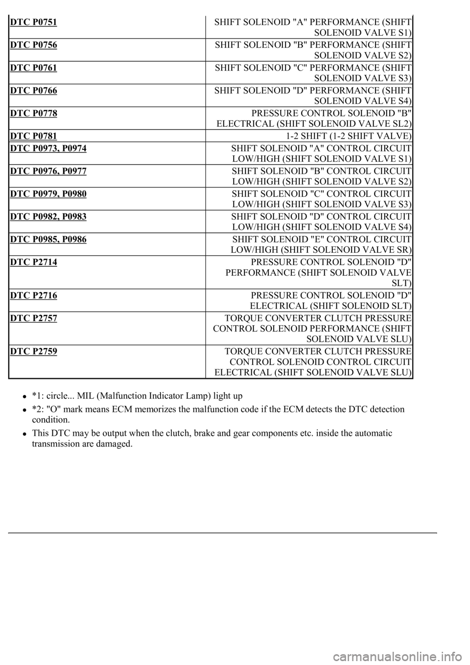
*1: circle... MIL (Malfunction Indicator Lamp) light up
*2: "O" mark means ECM memorizes the malfunction code if the ECM detects the DTC detection
condition.
This DTC may be output when the clutch, brake and gear components etc. inside the automatic
transmission are dama
ged.
DTC P0751SHIFT SOLENOID "A" PERFORMANCE (SHIFT
SOLENOID VALVE S1)
DTC P0756SHIFT SOLENOID "B" PERFORMANCE (SHIFT
SOLENOID VALVE S2)
DTC P0761SHIFT SOLENOID "C" PERFORMANCE (SHIFT
SOLENOID VALVE S3)
DTC P0766SHIFT SOLENOID "D" PERFORMANCE (SHIFT
SOLENOID VALVE S4)
DTC P0778PRESSURE CONTROL SOLENOID "B"
ELECTRICAL (SHIFT SOLENOID VALVE SL2)
DTC P07811-2 SHIFT (1-2 SHIFT VALVE)
DTC P0973, P0974SHIFT SOLENOID "A" CONTROL CIRCUIT
LOW/HIGH (SHIFT SOLENOID VALVE S1)
DTC P0976, P0977SHIFT SOLENOID "B" CONTROL CIRCUIT
LOW/HIGH (SHIFT SOLENOID VALVE S2)
DTC P0979, P0980SHIFT SOLENOID "C" CONTROL CIRCUIT
LOW/HIGH (SHIFT SOLENOID VALVE S3)
DTC P0982, P0983SHIFT SOLENOID "D" CONTROL CIRCUIT
LOW/HIGH (SHIFT SOLENOID VALVE S4)
DTC P0985, P0986SHIFT SOLENOID "E" CONTROL CIRCUIT
LOW/HIGH (SHIFT SOLENOID VALVE SR)
DTC P2714PRESSURE CONTROL SOLENOID "D"
PERFORMANCE (SHIFT SOLENOID VALVE
SLT)
DTC P2716PRESSURE CONTROL SOLENOID "D"
ELECTRICAL (SHIFT SOLENOID SLT)
DTC P2757TORQUE CONVERTER CLUTCH PRESSURE
CONTROL SOLENOID PERFORMANCE (SHIFT
SOLENOID VALVE SLU)
DTC P2759TORQUE CONVERTER CLUTCH PRESSURE
CONTROL SOLENOID CONTROL CIRCUIT
ELECTRICAL (SHIFT SOLENOID VALVE SLU)
Page 2759 of 4500

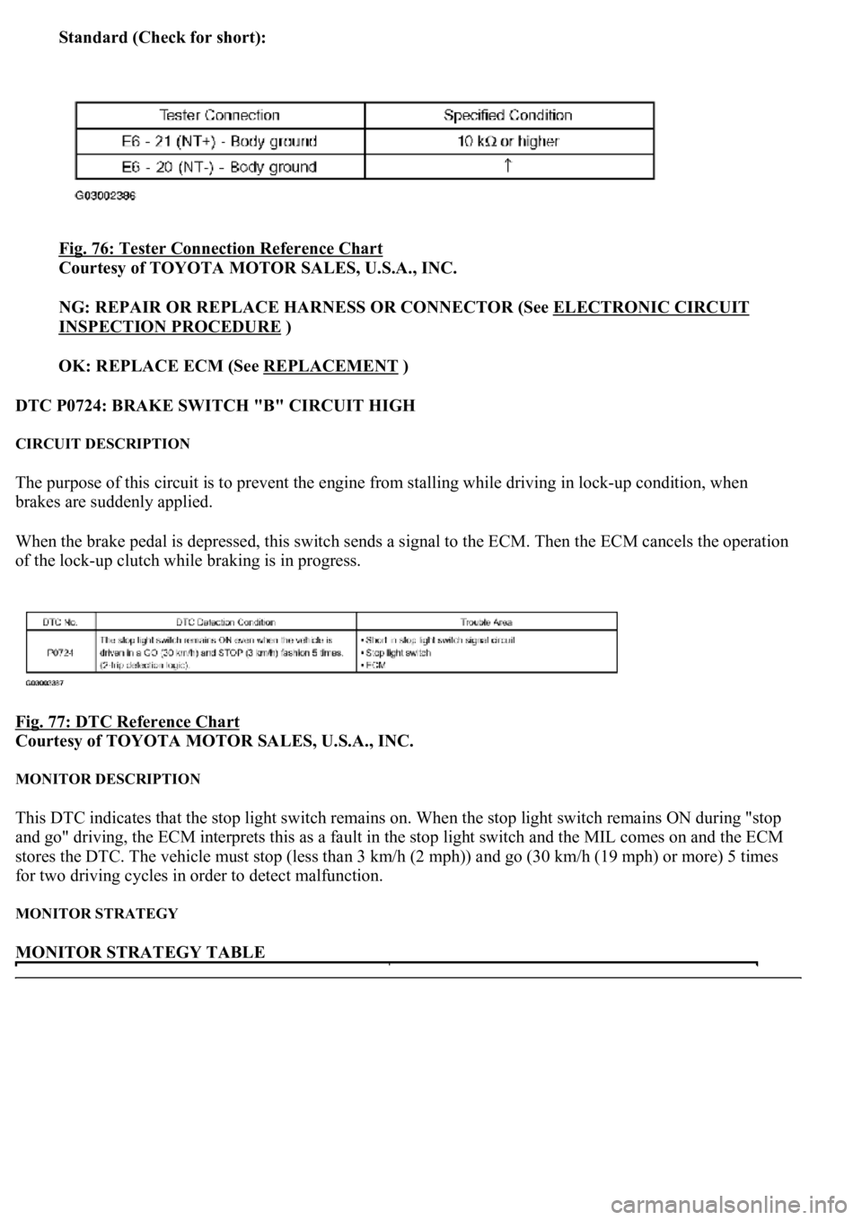
Standard (Check for short):
Fig. 76: Tester Connection Reference Chart
Courtesy of TOYOTA MOTOR SALES, U.S.A., INC.
NG: REPAIR OR REPLACE HARNESS OR CONNECTOR (See ELECTRONIC CIRCUIT
INSPECTION PROCEDURE )
OK: REPLACE ECM (See REPLACEMENT
)
DTC P0724: BRAKE SWITCH "B" CIRCUIT HIGH
CIRCUIT DESCRIPTION
The purpose of this circuit is to prevent the engine from stalling while driving in lock-up condition, when
brakes are suddenly applied.
When the brake pedal is depressed, this switch sends a signal to the ECM. Then the ECM cancels the operation
of the lock-up clutch while braking is in progress.
Fig. 77: DTC Reference Chart
Courtesy of TOYOTA MOTOR SALES, U.S.A., INC.
MONITOR DESCRIPTION
This DTC indicates that the stop light switch remains on. When the stop light switch remains ON during "stop
and go" driving, the ECM interprets this as a fault in the stop light switch and the MIL comes on and the ECM
stores the DTC. The vehicle must stop (less than 3 km/h (2 mph)) and go (30 km/h (19 mph) or more) 5 times
for two driving cycles in order to detect malfunction.
MONITOR STRATEGY
MONITOR STRATEGY TABLE
Page 2764 of 4500
OK: REPLACE ECM (See REPLACEMENT)
DTC P0729: GEAR 6 INCORRECT RATIO
SYSTEM DESCRIPTION
The ECM uses signals from the output speed sensor SP2 and input speed sensor NT to detect the actual gear
position (1st, 2nd, 3rd, 4th, 5th or 6th gear). Then the ECM compares the actual gear with the shift schedule in
the ECM memory to detect mechanical problems of the shift solenoid valves, valve body or automatic
transmission (clutch, brake or gear, etc.).
Fig. 83: Identifying Valve Body
Courtesy of TOYOTA MOTOR SALES, U.S.A., INC.