Page 2450 of 4500
Fig. 18: Multi-Information Display Chart On Combination Meter
Courtesy of TOYOTA MOTOR SALES, U.S.A., INC.
HINT:
The indication is immediately set to "LONG" each time the engine is started.
If a normal system code is displayed during the DTC check but the problem still occurs, check the suspected
areas for each problem symptom in the order given in the table below and proceed to the relevant
troubleshooting page.
HINT:
Inspect the "Fuse" and "Relay" before confirming the suspected areas as shown in the chart below. Inspect each
suspected area for the correspondin
g symptom in numerical order.
Page 2469 of 4500

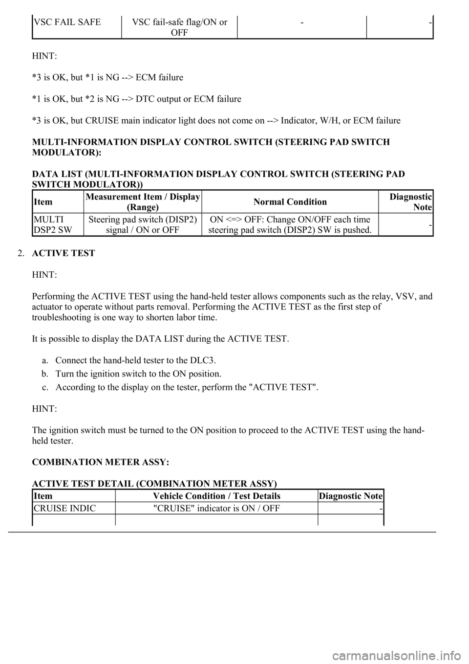
HINT:
*3 is OK, but *1 is NG --> ECM failure
*1 is OK, but *2 is NG --> DTC output or ECM failure
*3 is OK, but CRUISE main indicator light does not come on --> Indicator, W/H, or ECM failure
MULTI-INFORMATION DISPLAY CONTROL SWITCH (STEERING PAD SWITCH
MODULATOR):
DATA LIST (MULTI-INFORMATION DISPLAY CONTROL SWITCH (STEERING PAD
SWITCH MODULATOR))
2.ACTIVE TEST
HINT:
Performing the ACTIVE TEST using the hand-held tester allows components such as the relay, VSV, and
actuator to operate without parts removal. Performing the ACTIVE TEST as the first step of
troubleshooting is one way to shorten labor time.
It is possible to display the DATA LIST during the ACTIVE TEST.
a. Connect the hand-held tester to the DLC3.
b. Turn the ignition switch to the ON position.
c. According to the display on the tester, perform the "ACTIVE TEST".
HINT:
The ignition switch must be turned to the ON position to proceed to the ACTIVE TEST using the hand-
held tester.
COMBINATION METER ASSY:
ACTIVE TEST DETAIL (COMBINATION METER ASSY)
VSC FAIL SAFEVSC fail-safe flag/ON or
OFF--
ItemMeasurement Item / Display
(Range)Normal ConditionDiagnostic
Note
MULTI
DSP2 SWSteering pad switch (DISP2)
signal / ON or OFFON <=> OFF: Change ON/OFF each time
steering pad switch (DISP2) SW is pushed.-
ItemVehicle Condition / Test DetailsDiagnostic Note
CRUISE INDIC"CRUISE" indicator is ON / OFF-
Page 2550 of 4500
Fig. 18: Multi-Information Display Chart On Combination Meter
Courtesy of TOYOTA MOTOR SALES, U.S.A., INC.
HINT:
The indication is immediately set to "LONG" each time the engine is started.
If a normal system code is displayed during the DTC check but the problem still occurs, check the suspected
areas for each problem symptom in the order given in the table below and proceed to the relevant
troubleshooting page.
HINT:
Inspect the "Fuse" and "Relay" before confirming the suspected areas as shown in the Fig. 19
below. Inspect
each suspected area for the correspondin
g symptom in numerical order.
Page 2569 of 4500
Fig. 42: Data List Chart - CC (ECM) (2 Of 2)
Courtesy of TOYOTA MOTOR SALES, U.S.A., INC.
MULTI-INFORMATION DISPLAY CONTROL SWITCH (STEERING PAD SWITCH
MODULATOR):
DATA LIST (MULTI-INFORMATION DISPLAY CONTROL SWITCH (STEERING PAD
SWITCH MODULATOR))
2.ACTIVE TEST
HINT:
Performing the ACTIVE TEST using the hand-held tester allows components such as the relay, VSV, and
actuator to operate without parts removal. Performing the ACTIVE TEST as the first step of
troubleshooting is one way to shorten labor time.
It is possible to displa
y the DATA LIST during the ACTIVE TEST.
Item
Measurement Item / Display
(Range)
Normal ConditionDiagnostic Note
MULTI DSP2
SWSteering pad switch (DISP2)
signal / ON or OFFON <=> OFF: Change ON/OFF
each time steering pad switch
(DISP2) SW is pushed.-
Page 2627 of 4500

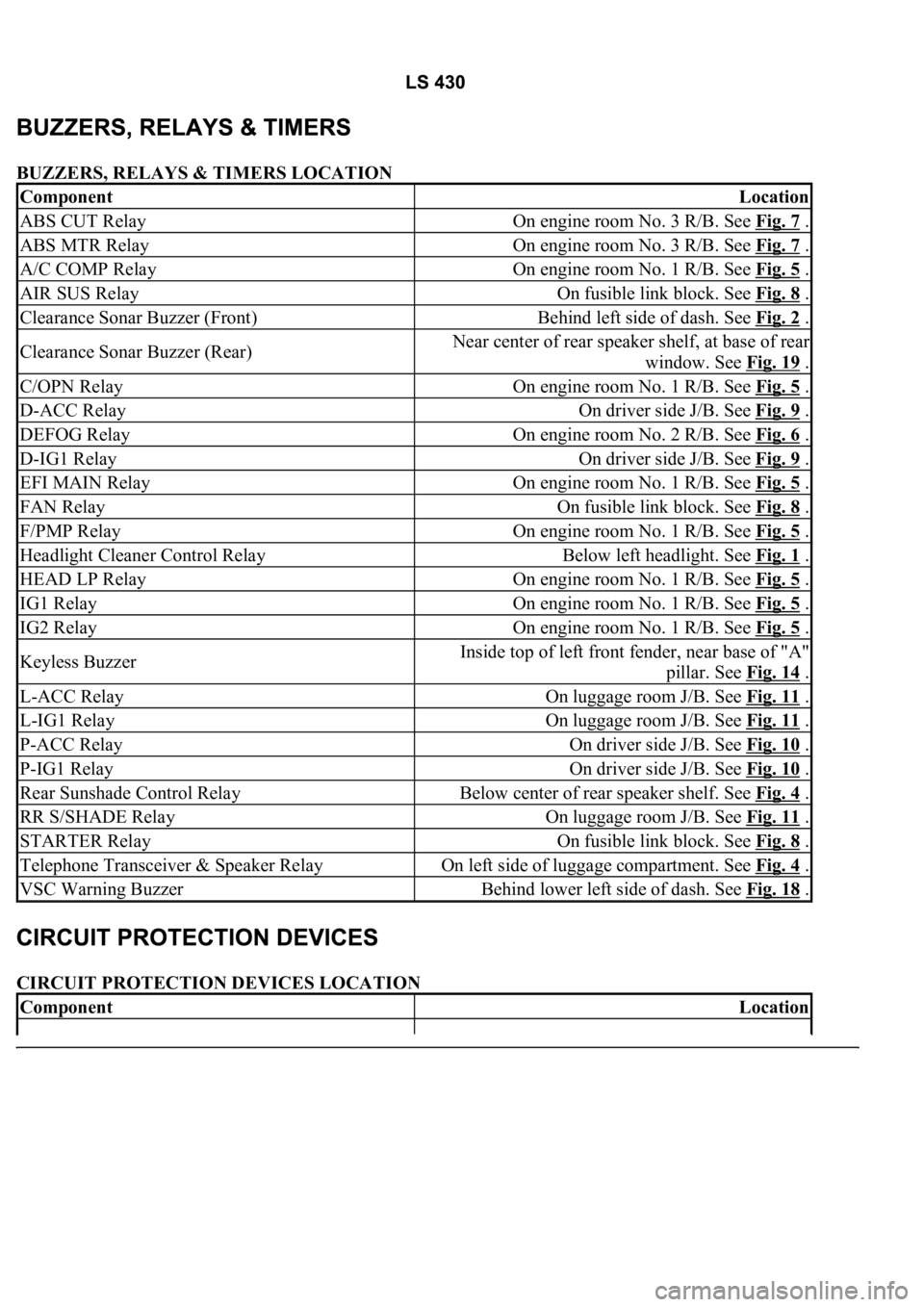
BUZZERS, RELAYS & TIMERS LOCATION
CIRCUIT PROTECTION DEVICES LOCATION
ComponentLocation
ABS CUT RelayOn engine room No. 3 R/B. See Fig. 7 .
ABS MTR RelayOn engine room No. 3 R/B. See Fig. 7 .
A/C COMP RelayOn engine room No. 1 R/B. See Fig. 5 .
AIR SUS RelayOn fusible link block. See Fig. 8 .
Clearance Sonar Buzzer (Front)Behind left side of dash. See Fig. 2 .
Clearance Sonar Buzzer (Rear)Near center of rear speaker shelf, at base of rear
window. See Fig. 19
.
C/OPN RelayOn engine room No. 1 R/B. See Fig. 5 .
D-ACC RelayOn driver side J/B. See Fig. 9 .
DEFOG RelayOn engine room No. 2 R/B. See Fig. 6 .
D-IG1 RelayOn driver side J/B. See Fig. 9 .
EFI MAIN RelayOn engine room No. 1 R/B. See Fig. 5 .
FAN RelayOn fusible link block. See Fig. 8 .
F/PMP RelayOn engine room No. 1 R/B. See Fig. 5 .
Headlight Cleaner Control RelayBelow left headlight. See Fig. 1 .
HEAD LP RelayOn engine room No. 1 R/B. See Fig. 5 .
IG1 RelayOn engine room No. 1 R/B. See Fig. 5 .
IG2 RelayOn engine room No. 1 R/B. See Fig. 5 .
Keyless BuzzerInside top of left front fender, near base of "A"
pillar. See Fig. 14
.
L-ACC RelayOn luggage room J/B. See Fig. 11 .
L-IG1 RelayOn luggage room J/B. See Fig. 11 .
P-ACC RelayOn driver side J/B. See Fig. 10 .
P-IG1 RelayOn driver side J/B. See Fig. 10 .
Rear Sunshade Control RelayBelow center of rear speaker shelf. See Fig. 4 .
RR S/SHADE RelayOn luggage room J/B. See Fig. 11 .
STARTER RelayOn fusible link block. See Fig. 8 .
Telephone Transceiver & Speaker RelayOn left side of luggage compartment. See Fig. 4 .
VSC Warning BuzzerBehind lower left side of dash. See Fig. 18 .
ComponentLocation
Page 2637 of 4500

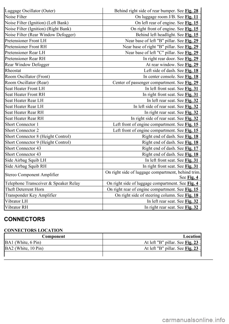
CONNECTORS LOCATION
Luggage Oscillator (Outer)Behind right side of rear bumper. See Fig. 28 .
Noise FilterOn luggage room J/B. See Fig. 11 .
Noise Filter (Ignition) (Left Bank)On left rear of engine. See Fig. 15 .
Noise Filter (Ignition) (Right Bank)On right front of engine. See Fig. 15 .
Noise Filter (Rear Window Defogger)Behind left headlight. See Fig. 15 .
Pretensioner Front LHNear base of left "B" pillar. See Fig. 29 .
Pretensioner Front RHNear base of right "B" pillar. See Fig. 29 .
Pretensioner Rear LHNear base of left "C" pillar. See Fig. 29 .
Pretensioner Rear RHIn right rear door. See Fig. 29 .
Rear Window DefoggerAt rear window. See Fig. 29 .
RheostatLeft side of dash. See Fig. 18 .
Room Oscillator (Front)In center console. See Fig. 18 .
Room Oscillator (Rear)Center of passenger compartment. See Fig. 29 .
Seat Heater Front LHIn left front seat. See Fig. 31 .
Seat Heater Front RHIn right front seat. See Fig. 31 .
Seat Heater Rear LHIn left rear seat. See Fig. 32 .
Seat Heater Rear LHIn left side of rear seat. See Fig. 32 .
Seat Heater Rear RHIn right rear seat. See Fig. 32 .
Seat Heater Rear RHIn right side of rear seat. See Fig. 32 .
Short Connector 1Left front of engine compartment. See Fig. 15 .
Short Connector 2Left front of engine compartment. See Fig. 15 .
Short Connector 8 (Height Control)Right end of dash. See Fig. 18 .
Short Connector 9 (Height Control)Right end of dash. See Fig. 18 .
Short Connector 43Right end of dash. See Fig. 17 .
Short Connector 43Right end of dash. See Fig. 18 .
Side Airbag Squib LHIn left front seat. See Fig. 31 .
Side Airbag Squib RHIn right front seat. See Fig. 31 .
Stereo Component AmplifierOn right side of luggage compartment, behind trim.
See Fig. 4
.
Telephone Transceiver & Speaker RelayOn right side of luggage compartment. See Fig. 4 .
Theft Deterrent HornOn right rear of engine compartment. See Fig. 15 .
Transponder Key AmplifierOn right side of steering column. See Fig. 18 .
Vibrator LHIn left rear seat. See Fig. 32 .
Vibrator RHIn right rear seat. See Fig. 32 .
ComponentLocation
BA1 (White, 6 Pin)At left "B" pillar. See Fig. 23 .
BA2 (White, 10 Pin)At left "B" pillar. See Fig. 23 .
Page 2724 of 4500
Fig. 45: Identifying Data List Reference (2 Of 2)
Courtesy of TOYOTA MOTOR SALES, U.S.A., INC.
2.ACTIVE TEST
HINT:
Performing the ACTIVE TEST using the hand-held tester allows the relay, VSV, actuator and so on to
operate without parts removal. Performing the ACTIVE TEST as the first step of troubleshooting is one
method to shorten labor time.
It is possible to display the DATA LIST during the ACTIVE TEST.
a. Warm up the engine.
b. Turn the ignition switch off.
c. Connect the hand-held tester together with the CAN VIM (controller area network vehicle interface
module) to the DLC3.
d. Turn the ignition switch to the ON position.
e. Push the "ON" button of the hand-held tester.
f. Select the item "DIAGNOSIS/ENHANCED OBD II/ACTIVE TEST".
g. According to the display on tester, perform the "ACTIVE TEST".
Page 2767 of 4500

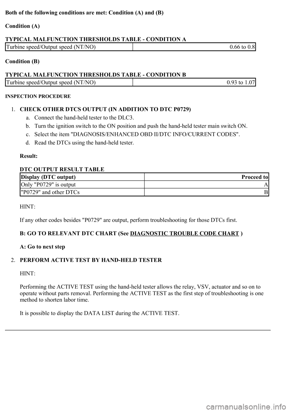
Both of the following conditions are met: Condition (A) and (B)
Condition (A)
TYPICAL MALFUNCTION THRESHOLDS TABLE - CONDITION A
Condition (B)
TYPICAL MALFUNCTION THRESHOLDS TABLE - CONDITION B
INSPECTION PROCEDURE
1.CHECK OTHER DTCS OUTPUT (IN ADDITION TO DTC P0729)
a. Connect the hand-held tester to the DLC3.
b. Turn the ignition switch to the ON position and push the hand-held tester main switch ON.
c. Select the item "DIAGNOSIS/ENHANCED OBD II/DTC INFO/CURRENT CODES".
d. Read the DTCs using the hand-held tester.
Result:
DTC OUTPUT RESULT TABLE
HINT:
If any other codes besides "P0729" are output, perform troubleshooting for those DTCs first.
B: GO TO RELEVANT DTC CHART (See DIAGNOSTIC TROUBLE CODE CHART
)
A: Go to next step
2.PERFORM ACTIVE TEST BY HAND-HELD TESTER
HINT:
Performing the ACTIVE TEST using the hand-held tester allows the relay, VSV, actuator and so on to
operate without parts removal. Performing the ACTIVE TEST as the first step of troubleshooting is one
method to shorten labor time.
It is possible to display the DATA LIST during the ACTIVE TEST.
Turbine speed/Output speed (NT/NO)0.66 to 0.8
Turbine speed/Output speed (NT/NO)0.93 to 1.07
Display (DTC output)Proceed to
Only "P0729" is outputA
"P0729" and other DTCsB