Page 2859 of 4500
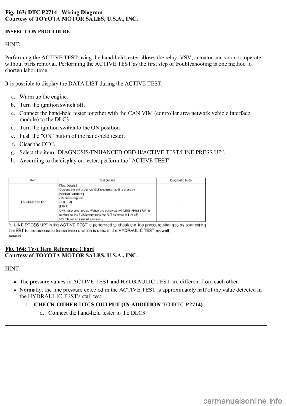
Fig. 163: DTC P2714 - Wiring Diagram
Courtesy of TOYOTA MOTOR SALES, U.S.A., INC.
INSPECTION PROCEDURE
HINT:
Performing the ACTIVE TEST using the hand-held tester allows the relay, VSV, actuator and so on to operate
without parts removal. Performing the ACTIVE TEST as the first step of troubleshooting is one method to
shorten labor time.
It is possible to display the DATA LIST during the ACTIVE TEST.
a. Warm up the engine.
b. Turn the ignition switch off.
c. Connect the hand-held tester together with the CAN VIM (controller area network vehicle interface
module) to the DLC3.
d. Turn the ignition switch to the ON position.
e. Push the "ON" button of the hand-held tester.
f. Clear the DTC.
g. Select the item "DIAGNOSIS/ENHANCED OBD II/ACTIVE TEST/LINE PRESS UP".
h. According to the display on tester, perform the "ACTIVE TEST".
Fig. 164: Test Item Reference Chart
Courtesy of TOYOTA MOTOR SALES, U.S.A., INC.
HINT:
The pressure values in ACTIVE TEST and HYDRAULIC TEST are different from each other.
Normally, the line pressure detected in the ACTIVE TEST is approximately half of the value detected in
the HYDRAULIC TEST's stall test.
1.CHECK OTHER DTCS OUTPUT (IN ADDITION TO DTC P2714)
a. Connect the han
d-held tester to the DLC3.
Page 2871 of 4500
relay valve and locks the torque converter clutch.
If the ECM detects no lock-up after lock-up has been requested or if it detects lock-up when it is not requested,
the ECM interprets this as a fault in the shift solenoid valve SLU or lock-up system performance.
The ECM will turn on the MIL and store the DTC.
Example:
When any of the following is met, the system judges it as a malfunction.
a. There is a difference in rotation between before and after torque converters even when the ECM
commands lock-up.
(Engine speed is at least 75 rpm greater than input turbine speed.)
b. There is no difference in rotation between before and after torque converters even when the ECM
commands lock-up off.
(The difference between engine speed and input turbine speed is less than 35 rpm.)
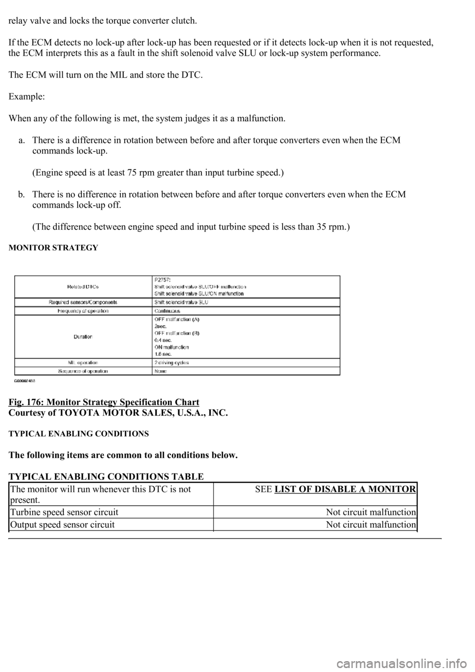
MONITOR STRATEGY
Fig. 176: Monitor Strategy Specification Chart
Courtesy of TOYOTA MOTOR SALES, U.S.A., INC.
TYPICAL ENABLING CONDITIONS
The following items are common to all conditions below.
TYPICAL ENABLING CONDITIONS TABLE
The monitor will run whenever this DTC is not
present.SEE LIST OF DISABLE A MONITOR
Turbine speed sensor circuitNot circuit malfunction
Output speed sensor circuitNot circuit malfunction
Page 2873 of 4500
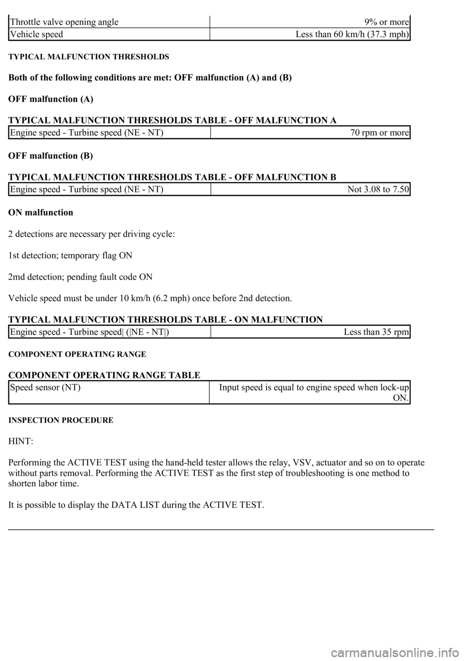
TYPICAL MALFUNCTION THRESHOLDS
Both of the following conditions are met: OFF malfunction (A) and (B)
OFF malfunction (A)
TYPICAL MALFUNCTION THRESHOLDS TABLE - OFF MALFUNCTION A
OFF malfunction (B)
TYPICAL MALFUNCTION THRESHOLDS TABLE - OFF MALFUNCTION B
ON malfunction
2 detections are necessary per driving cycle:
1st detection; temporary flag ON
2md detection; pending fault code ON
Vehicle speed must be under 10 km/h (6.2 mph) once before 2nd detection.
TYPICAL MALFUNCTION THRESHOLDS TABLE - ON MALFUNCTION
COMPONENT OPERATING RANGE
COMPONENT OPERATING RANGE TABLE
INSPECTION PROCEDURE
HINT:
Performing the ACTIVE TEST using the hand-held tester allows the relay, VSV, actuator and so on to operate
without parts removal. Performing the ACTIVE TEST as the first step of troubleshooting is one method to
shorten labor time.
It is possible to display the DATA LIST during the ACTIVE TEST.
Throttle valve opening angle9% or more
Vehicle speedLess than 60 km/h (37.3 mph)
Engine speed - Turbine speed (NE - NT)70 rpm or more
Engine speed - Turbine speed (NE - NT)Not 3.08 to 7.50
Engine speed - Turbine speed| (|NE - NT|)Less than 35 rpm
Speed sensor (NT)Input speed is equal to engine speed when lock-up
ON.
Page 2952 of 4500
STANDARD:
If the result is not as specified, replace the sensor.
6.INSPECT KNOCK SENSOR
Fig. 12: Inspecting Knock Sensor
Courtesy of TOYOTA MOTOR SALES, U.S.A., INC.
a. Using an ohmmeter, measure the resistance between the terminals.
Standard: 120 to 280 kohms at 20°C (68°F)
If the result is not as specified, replace the sensor.
7.INSPECT RELAY (Marking: EFI MAIN, C/OPN)
ConditionSpecified Condition
Approx. 20°C (68°F)2.32 to 2.59 kohms
Approx. 80°C (176°F)0.31 to 0.326 kohms
Page 2953 of 4500
Fig. 13: Measuring Resistance Of Relay
Courtesy of TOYOTA MOTOR SALES, U.S.A., INC.
a. Remove the EFI and C/OPN relays from the engine room R/B.
b. Measure the resistance of the relay.
STANDARD:
If the result is not as specified, replace the relay.
8.INSPECT RELAY (Marking: F/PMP)
TerminalsSpecified Condition
3 - 510 kohms or higher
3 - 5Below 1 ohms (when battery voltage is applied to terminals 1 and 2)
Page 2954 of 4500
Fig. 14: Measuring Resistance Of F/Pmp Relay
Courtesy of TOYOTA MOTOR SALES, U.S.A., INC.
a. Remove the F/PMP relay from the engine room R/B.
b. Measure the resistance of the F/PMP relay.
STANDARD:
If the result is not as specified, replace the relay.
COMPONENTS
TerminalsSpecified Condition
3 - 4Below 1 ohms
3 - 410 kohms or higher (when battery voltage is applied to terminals 1 and 2)
Page 3199 of 4500
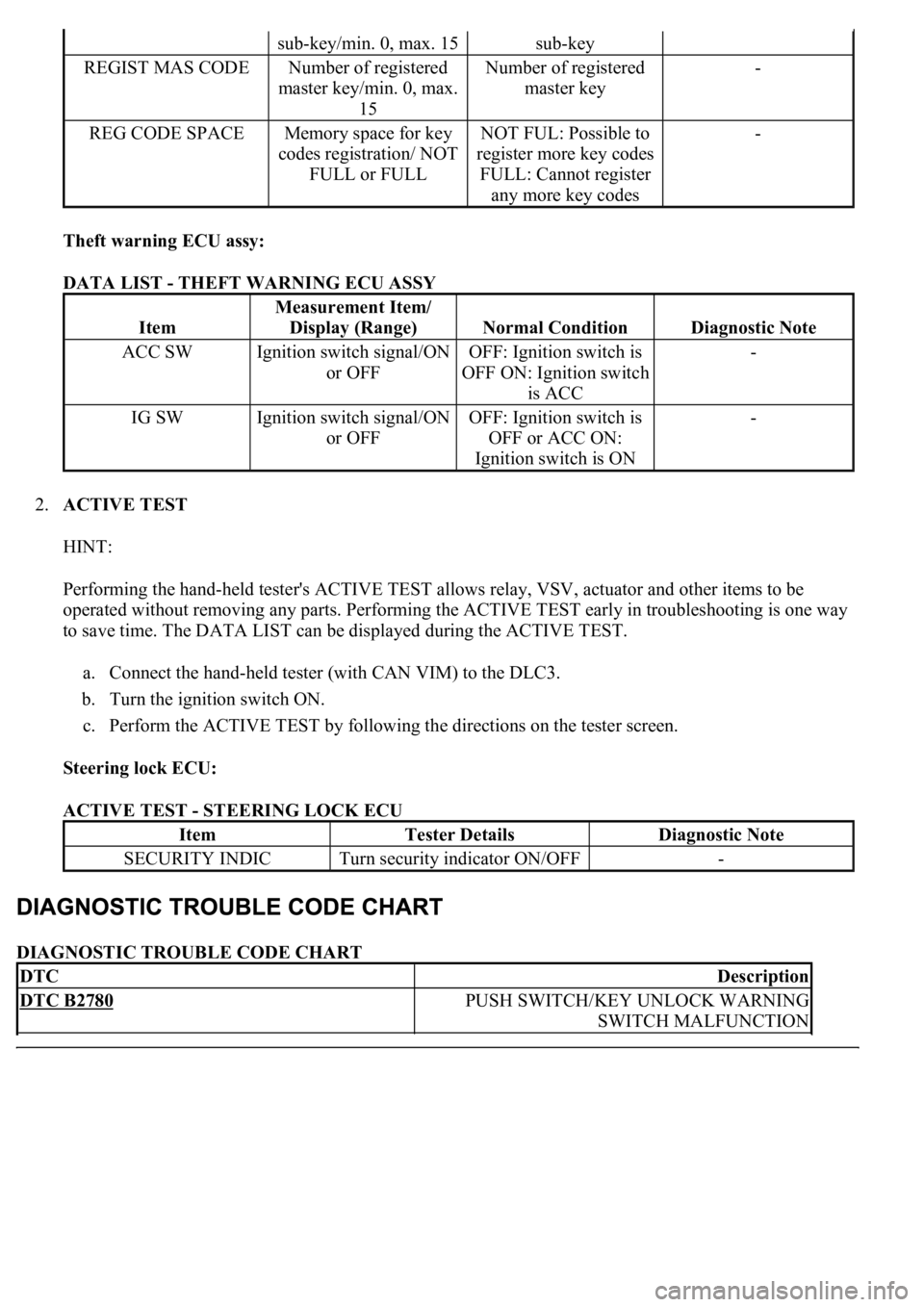
Theft warning ECU assy:
DATA LIST - THEFT WARNING ECU ASSY
2.ACTIVE TEST
HINT:
Performing the hand-held tester's ACTIVE TEST allows relay, VSV, actuator and other items to be
operated without removing any parts. Performing the ACTIVE TEST early in troubleshooting is one way
to save time. The DATA LIST can be displayed during the ACTIVE TEST.
a. Connect the hand-held tester (with CAN VIM) to the DLC3.
b. Turn the ignition switch ON.
c. Perform the ACTIVE TEST by following the directions on the tester screen.
Steering lock ECU:
ACTIVE TEST - STEERING LOCK ECU
DIAGNOSTIC TROUBLE CODE CHART
sub-key/min. 0, max. 15sub-key
REGIST MAS CODENumber of registered
master key/min. 0, max.
15Number of registered
master key-
REG CODE SPACEMemory space for key
codes registration/ NOT
FULL or FULLNOT FUL: Possible to
register more key codes
FULL: Cannot register
any more key codes-
Item
Measurement Item/
Display (Range)
Normal ConditionDiagnostic Note
ACC SWIgnition switch signal/ON
or OFFOFF: Ignition switch is
OFF ON: Ignition switch
is ACC-
IG SWIgnition switch signal/ON
or OFFOFF: Ignition switch is
OFF or ACC ON:
Ignition switch is ON-
ItemTester DetailsDiagnostic Note
SECURITY INDICTurn security indicator ON/OFF-
DTCDescription
DTC B2780PUSH SWITCH/KEY UNLOCK WARNING
SWITCH MALFUNCTION
Page 3254 of 4500
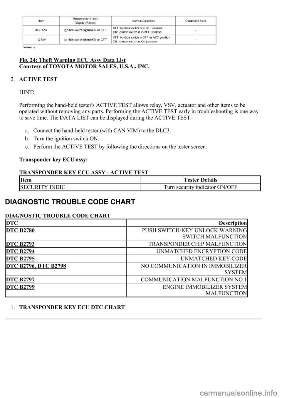
Fig. 24: Theft Warning ECU Assy Data List
Courtesy of TOYOTA MOTOR SALES, U.S.A., INC.
2.ACTIVE TEST
HINT:
Performing the hand-held tester's ACTIVE TEST allows relay, VSV, actuator and other items to be
operated without removing any parts. Performing the ACTIVE TEST early in troubleshooting is one way
to save time. The DATA LIST can be displayed during the ACTIVE TEST.
a. Connect the hand-held tester (with CAN VIM) to the DLC3.
b. Turn the ignition switch ON.
c. Perform the ACTIVE TEST by following the directions on the tester screen.
Transponder key ECU assy:
TRANSPONDER KEY ECU ASSY - ACTIVE TEST
DIAGNOSTIC TROUBLE CODE CHART
1.TRANSPONDER KEY ECU DTC CHART
ItemTester Details
SECURITY INDICTurn security indicator ON/OFF
DTCDescription
DTC B2780PUSH SWITCH/KEY UNLOCK WARNING
SWITCH MALFUNCTION
DTC B2793TRANSPONDER CHIP MALFUNCTION
DTC B2794UNMATCHED ENCRYPTION CODE
DTC B2795UNMATCHED KEY CODE
DTC B2796, DTC B2798NO COMMUNICATION IN IMMOBILIZER
SYSTEM
DTC B2797COMMUNICATION MALFUNCTION NO.1
DTC B2799ENGINE IMMOBILIZER SYSTEM
MALFUNCTION