2003 DODGE RAM C1 connector
[x] Cancel search: C1 connectorPage 2316 of 2895
Check the two separator plates for distortion or
damage of any kind. Inspect the upper housing,
lower housing, 3-4 accumulator housing, and transfer
plate carefully. Be sure all fluid passages are clean
and clear. Check condition of the upper housing and
transfer plate check balls as well. The check balls
and ball seats must not be worn or damaged.
Trial fit each valve and plug in its bore to check
freedom of operation. When clean and dry, the valves
and plugs should drop freely into the bores.
Valve body bores do not change dimensionally with
use. If the valve body functioned correctly when new,
it will continue to operate properly after cleaning and
inspection. It should not be necessary to replace a
valve body assembly unless it is damaged in han-
dling.
The only serviceable valve body components are
listed below. The remaining valve body components
are serviced only as part of a complete valve body
assembly. Serviceable parts are:
²dual solenoid and harness assembly
²solenoid gasket
²solenoid case connector O-rings and shoulder
bolt
²switch valve and spring
²pressure adjusting screw and bracket assembly
²throttle lever
²manual lever and shaft seal
²throttle lever shaft seal, washer, and E-clip
²fluid filter and screws
²detent ball and spring
²valve body screws
²governor pressure solenoid
²governor pressure sensor and retaining clip
²park lock rod and E-clipASSEMBLY
CAUTION: Do not force valves or plugs into place
during reassembly. If the valve body bores, valves
and plugs are free of distortion or burrs, the valve
body components should all slide into place easily.
In addition, do not overtighten the transfer plate
and valve body screws during reassembly. Over-
tightening can distort the housings resulting in
valve sticking, cross leakage and unsatisfactory
operation. Tighten valve body screws to recom-
mended torque only.
LOWER HOUSING
(1) Lubricate valves, springs, and the housing
valve and plug bores with clean transmission fluid
(Fig. 307).
(2) Install 3-4 timing valve spring and valve in
lower housing.
(3) Install 3-4 quick fill valve in lower housing.
(4) Install 3-4 quick fill valve spring and plug in
housing.
(5) Install timing valve end plate. Tighten end
plate screws to 4 N´m (35 in. lbs.) torque.
DRAUTOMATIC TRANSMISSION - 48RE 21 - 477
VALVE BODY (Continued)
Page 2317 of 2895
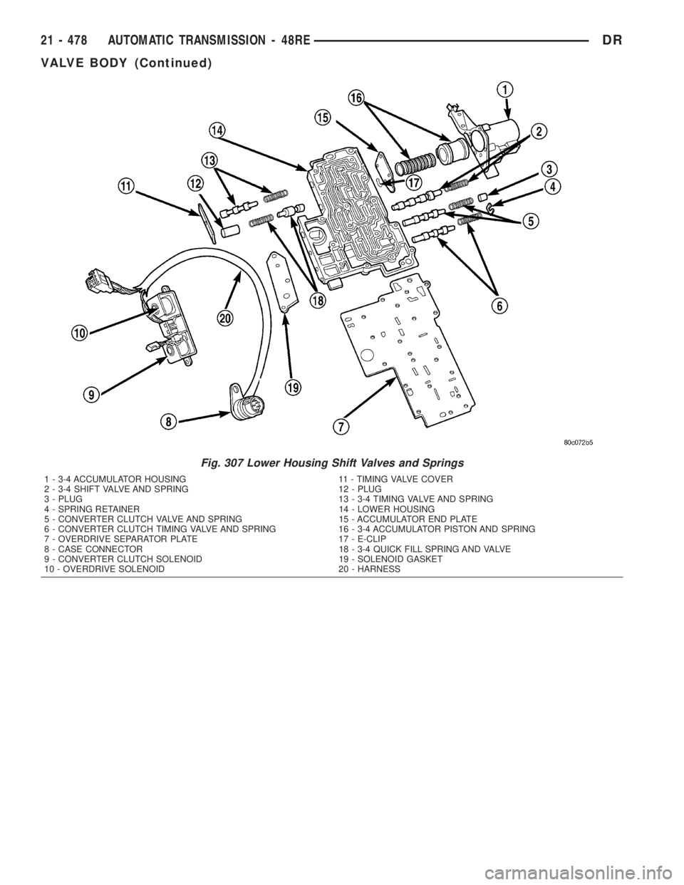
Fig. 307 Lower Housing Shift Valves and Springs
1 - 3-4 ACCUMULATOR HOUSING 11 - TIMING VALVE COVER
2 - 3-4 SHIFT VALVE AND SPRING 12 - PLUG
3 - PLUG 13 - 3-4 TIMING VALVE AND SPRING
4 - SPRING RETAINER 14 - LOWER HOUSING
5 - CONVERTER CLUTCH VALVE AND SPRING 15 - ACCUMULATOR END PLATE
6 - CONVERTER CLUTCH TIMING VALVE AND SPRING 16 - 3-4 ACCUMULATOR PISTON AND SPRING
7 - OVERDRIVE SEPARATOR PLATE 17 - E-CLIP
8 - CASE CONNECTOR 18 - 3-4 QUICK FILL SPRING AND VALVE
9 - CONVERTER CLUTCH SOLENOID 19 - SOLENOID GASKET
10 - OVERDRIVE SOLENOID 20 - HARNESS
21 - 478 AUTOMATIC TRANSMISSION - 48REDR
VALVE BODY (Continued)
Page 2324 of 2895
VALVE BODY FINAL
(1) Install boost valve, valve spring, retainer and
cover plate. Tighten cover plate screws to 4 N´m (35
in. lbs.) torque.
(2) Insert manual lever detent spring in upper
housing.
(3) Position detent ball on end of spring. Then hold
detent ball and spring in detent housing with
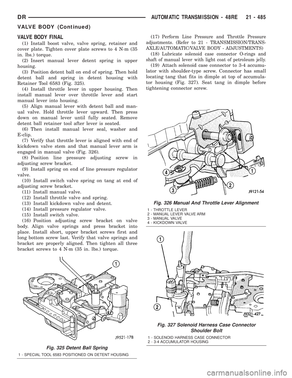
Retainer Tool 6583 (Fig. 325).
(4) Install throttle lever in upper housing. Then
install manual lever over throttle lever and start
manual lever into housing.
(5) Align manual lever with detent ball and man-
ual valve. Hold throttle lever upward. Then press
down on manual lever until fully seated. Remove
detent ball retainer tool after lever is seated.
(6) Then install manual lever seal, washer and
E-clip.
(7) Verify that throttle lever is aligned with end of
kickdown valve stem and that manual lever arm is
engaged in manual valve (Fig. 326).
(8) Position line pressure adjusting screw in
adjusting screw bracket.
(9) Install spring on end of line pressure regulator
valve.
(10) Install switch valve spring on tang at end of
adjusting screw bracket.
(11) Install manual valve.
(12) Install throttle valve and spring.
(13) Install kickdown valve and detent.
(14) Install pressure regulator valve.
(15) Install switch valve.
(16) Position adjusting screw bracket on valve
body. Align valve springs and press bracket into
place. Install short, upper bracket screws first and
long bottom screw last. Verify that valve springs and
bracket are properly aligned. Then tighten all three
bracket screws to 4 N´m (35 in. lbs.) torque.(17)
Perform Line Pressure and Throttle Pressure
adjustments. (Refer to 21 - TRANSMISSION/TRANS-
AXLE/AUTOMATIC/VALVE BODY - ADJUSTMENTS)
(18)Lubricate solenoid case connector O-rings and
shaft of manual lever with light coat of petroleum jelly.
(19) Attach solenoid case connector to 3-4 accumu-
lator with shoulder-type screw. Connector has small
locating tang that fits in dimple at top of accumula-
tor housing (Fig. 327). Seat tang in dimple before
tightening connector screw.
Fig. 325 Detent Ball Spring
1 - SPECIAL TOOL 6583 POSITIONED ON DETENT HOUSING
Fig. 326 Manual And Throttle Lever Alignment
1 - THROTTLE LEVER
2 - MANUAL LEVER VALVE ARM
3 - MANUAL VALVE
4 - KICKDOWN VALVE
Fig. 327 Solenoid Harness Case Connector
Shoulder Bolt
1 - SOLENOID HARNESS CASE CONNECTOR
2 - 3-4 ACCUMULATOR HOUSING
DRAUTOMATIC TRANSMISSION - 48RE 21 - 485
VALVE BODY (Continued)
Page 2325 of 2895
(20)Install solenoid assembly and gasket. Tighten
solenoid attaching screws to 8 N´m (72 in. lbs.) torque.
(21) Verify that solenoid wire harness is properly
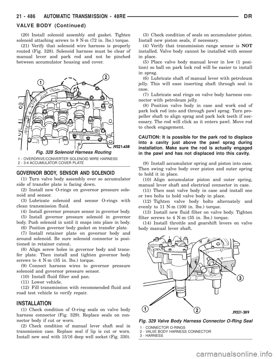
routed (Fig. 328). Solenoid harness must be clear of
manual lever and park rod and not be pinched
between accumulator housing and cover.
GOVERNOR BODY, SENSOR AND SOLENOID
(1) Turn valve body assembly over so accumulator
side of transfer plate is facing down.
(2) Install new O-rings on governor pressure sole-
noid and sensor.
(3) Lubricate solenoid and sensor O-rings with
clean transmission fluid.
(4)
Install governor pressure sensor in governor body.
(5)Install governor pressure solenoid in governor
body. Push solenoid in until it snaps into place in body.
(6)Position governor body gasket on transfer plate.
(7) Install retainer plate on governor body and
around solenoid. Be sure solenoid connector is posi-
tioned in retainer cutout.
(8) Align screw holes in governor body and trans-
fer plate. Then install and tighten governor body
screws to 4 N´m (35 in. lbs.) torque.
(9) Connect harness wires to governor pressure
solenoid and governor pressure sensor.
(10) Install fluid filter and pan.
(11) Lower vehicle.
(12) Fill transmission with recommended fluid and
road test vehicle to verify repair.
INSTALLATION
(1) Check condition of O-ring seals on valve body
harness connector (Fig. 329). Replace seals on con-
nector body if cut or worn.
(2)
Check condition of manual lever shaft seal in
transmission case. Replace seal if lip is cut or worn.
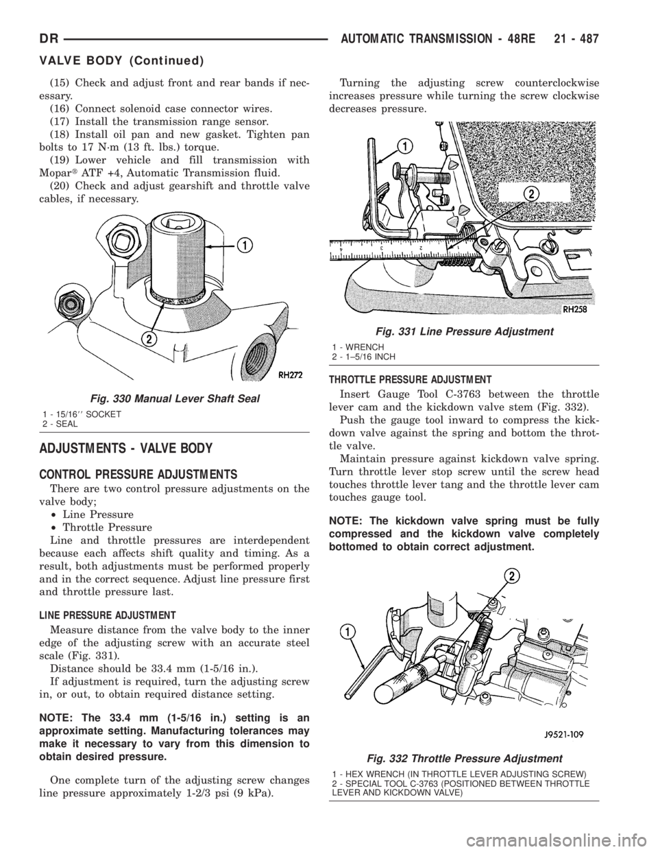
Install new seal with 15/16 deep well socket (Fig. 330).
(3) Check condition of seals on accumulator piston.
Install new piston seals, if necessary.
(4) Verify that transmission range sensor isNOT
installed. Valve body cannot be installed with sensor
in place.
(5) Place valve body manual lever in low (1 posi-
tion) so ball on park lock rod will be easier to install
in sprag.
(6) Lubricate shaft of manual lever with petroleum
jelly. This will ease inserting shaft through seal in
case.
(7) Lubricate seal rings on valve body harness con-
nector with petroleum jelly.
(8) Position valve body in case and work end of
park lock rod into and through pawl sprag. Turn pro-
peller shaft to align sprag and park lock teeth if nec-
essary. The rod will click as it enters pawl. Move rod
to check engagement.
CAUTION: It is possible for the park rod to displace
into a cavity just above the pawl sprag during
installation. Make sure the rod is actually engaged
in the pawl and has not displaced into this cavity.
(9) Install accumulator spring and piston into case.
Then swing valve body over piston and outer spring
to hold it in place.
(10) Align accumulator piston and outer spring,
manual lever shaft and electrical connector in case.
(11) Then seat valve body in case and install one
or two bolts to hold valve body in place.
(12) Tighten valve body bolts alternately and
evenly to 11 N´m (100 in. lbs.) torque.
(13) Install new fluid filter on valve body. Tighten
filter screws to 4 N´m (35 in. lbs.) torque.
(14) Install throttle and gearshift levers on valve
body manual lever shaft.
Fig. 329 Valve Body Harness Connector O-Ring Seal
1 - CONNECTOR O-RINGS
2 - VALVE BODY HARNESS CONNECTOR
3 - HARNESS
Fig. 328 Solenoid Harness Routing
1 - OVERDRIVE/CONVERTER SOLENOID WIRE HARNESS
2 - 3-4 ACCUMULATOR COVER PLATE
21 - 486 AUTOMATIC TRANSMISSION - 48REDR
VALVE BODY (Continued)
Page 2326 of 2895
(15) Check and adjust front and rear bands if nec-
essary.
(16) Connect solenoid case connector wires.
(17) Install the transmission range sensor.
(18) Install oil pan and new gasket. Tighten pan
bolts to 17 N´m (13 ft. lbs.) torque.
(19) Lower vehicle and fill transmission with
MopartATF +4, Automatic Transmission fluid.
(20) Check and adjust gearshift and throttle valve
cables, if necessary.
ADJUSTMENTS - VALVE BODY
CONTROL PRESSURE ADJUSTMENTS
There are two control pressure adjustments on the
valve body;
²Line Pressure
²Throttle Pressure
Line and throttle pressures are interdependent
because each affects shift quality and timing. As a
result, both adjustments must be performed properly
and in the correct sequence. Adjust line pressure first
and throttle pressure last.
LINE PRESSURE ADJUSTMENT
Measure distance from the valve body to the inner
edge of the adjusting screw with an accurate steel
scale (Fig. 331).
Distance should be 33.4 mm (1-5/16 in.).
If adjustment is required, turn the adjusting screw
in, or out, to obtain required distance setting.
NOTE: The 33.4 mm (1-5/16 in.) setting is an
approximate setting. Manufacturing tolerances may
make it necessary to vary from this dimension to
obtain desired pressure.
One complete turn of the adjusting screw changes
line pressure approximately 1-2/3 psi (9 kPa).Turning the adjusting screw counterclockwise
increases pressure while turning the screw clockwise
decreases pressure.
THROTTLE PRESSURE ADJUSTMENT
Insert Gauge Tool C-3763 between the throttle
lever cam and the kickdown valve stem (Fig. 332).
Push the gauge tool inward to compress the kick-
down valve against the spring and bottom the throt-
tle valve.
Maintain pressure against kickdown valve spring.
Turn throttle lever stop screw until the screw head
touches throttle lever tang and the throttle lever cam
touches gauge tool.
NOTE: The kickdown valve spring must be fully
compressed and the kickdown valve completely
bottomed to obtain correct adjustment.
Fig. 330 Manual Lever Shaft Seal
1 - 15/1688SOCKET
2 - SEAL
Fig. 331 Line Pressure Adjustment
1 - WRENCH
2 - 1±5/16 INCH
Fig. 332 Throttle Pressure Adjustment
1 - HEX WRENCH (IN THROTTLE LEVER ADJUSTING SCREW)
2 - SPECIAL TOOL C-3763 (POSITIONED BETWEEN THROTTLE
LEVER AND KICKDOWN VALVE)
DRAUTOMATIC TRANSMISSION - 48RE 21 - 487
VALVE BODY (Continued)
Page 2335 of 2895
(9) Disconnect and lower or remove any necessary
exhaust components.
(10) Remove the starter motor.
(11) Rotate crankshaft in clockwise direction until
converter bolts are accessible. Then remove bolts one
at a time. Rotate crankshaft with socket wrench on
dampener bolt.
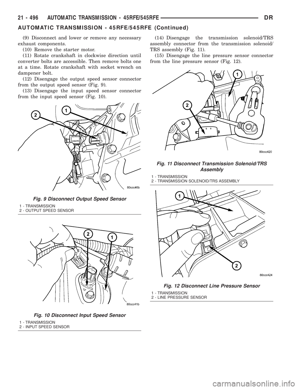
(12) Disengage the output speed sensor connector
from the output speed sensor (Fig. 9).
(13) Disengage the input speed sensor connector
from the input speed sensor (Fig. 10).(14) Disengage the transmission solenoid/TRS
assembly connector from the transmission solenoid/
TRS assembly (Fig. 11).
(15) Disengage the line pressure sensor connector
from the line pressure sensor (Fig. 12).
Fig. 9 Disconnect Output Speed Sensor
1 - TRANSMISSION
2 - OUTPUT SPEED SENSOR
Fig. 10 Disconnect Input Speed Sensor
1 - TRANSMISSION
2 - INPUT SPEED SENSOR
Fig. 11 Disconnect Transmission Solenoid/TRS
Assembly
1 - TRANSMISSION
2 - TRANSMISSION SOLENOID/TRS ASSEMBLY
Fig. 12 Disconnect Line Pressure Sensor
1 - TRANSMISSION
2 - LINE PRESSURE SENSOR
21 - 496 AUTOMATIC TRANSMISSION - 45RFE/545RFEDR
AUTOMATIC TRANSMISSION - 45RFE/545RFE (Continued)
Page 2350 of 2895

(21) Connect wires to solenoid and pressure switch
assembly (Fig. 55) connector, input (Fig. 56) and out-
put (Fig. 57) speed sensors, and line pressure sensor
(Fig. 58). Be sure transmission harnesses are prop-
erly routed.
CAUTION: It is essential that correct length bolts be
used to attach the converter to the driveplate. Bolts
that are too long will damage the clutch surface
inside the converter.(22) Install torque converter-to-driveplate bolts.
Tighten bolts to 31 N´m (270 in. lbs.).
(23) Install starter motor and cooler line bracket.
(24) Connect cooler lines to transmission.
(25) Install transmission fill tube.
(26) Install exhaust components, if necessary.
Fig. 55 Connect Transmission Solenoid
1 - TRANSMISSION
2 - TRANSMISSION SOLENOID/TRS ASSEMBLY
Fig. 56 Connect Input Speed Sensor
1 - TRANSMISSION
2 - INPUT SPEED SENSOR
Fig. 57 Connect Output Speed Sensor
1 - TRANSMISSION
2 - OUTPUT SPEED SENSOR
Fig. 58 Connect Line Pressure Sensor
1 - TRANSMISSION
2 - LINE PRESSURE SENSOR
DRAUTOMATIC TRANSMISSION - 45RFE/545RFE 21 - 511
AUTOMATIC TRANSMISSION - 45RFE/545RFE (Continued)
Page 2379 of 2895
BRAKE TRANSMISSION SHIFT
INTERLOCK SYSTEM
DESCRIPTION
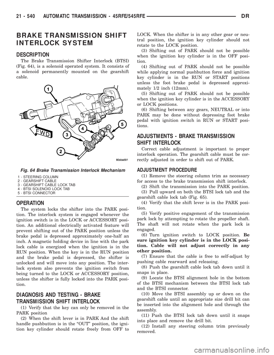
The Brake Transmission Shifter Interlock (BTSI)
(Fig. 64), is a solenoid operated system. It consists of
a solenoid permanently mounted on the gearshift
cable.
OPERATION
The system locks the shifter into the PARK posi-
tion. The interlock system is engaged whenever the
ignition switch is in the LOCK or ACCESSORY posi-
tion. An additional electrically activated feature will
prevent shifting out of the PARK position unless the
brake pedal is depressed approximately one-half an
inch. A magnetic holding device in line with the park
lock cable is energized when the ignition is in the
RUN position. When the key is in the RUN position
and the brake pedal is depressed, the shifter is
unlocked and will move into any position. The inter-
lock system also prevents the ignition switch from
being turned to the LOCK or ACCESSORY position,
unless the shifter is fully locked into the PARK posi-
tion.
DIAGNOSIS AND TESTING - BRAKE
TRANSMISSION SHIFT INTERLOCK
(1) Verify that the key can only be removed in the
PARK position
(2) When the shift lever is in PARK And the shift
handle pushbutton is in the ªOUTº position, the igni-
tion key cylinder should rotate freely from OFF toLOCK. When the shifter is in any other gear or neu-
tral position, the ignition key cylinder should not
rotate to the LOCK position.
(3) Shifting out of PARK should not be possible
when the ignition key cylinder is in the OFF posi-
tion.
(4) Shifting out of PARK should not be possible
while applying normal pushbutton force and ignition
key cylinder is in the RUN or START positions
unless the foot brake pedal is depressed approxi-
mately 1/2 inch (12mm).
(5) Shifting out of PARK should not be possible
when the ignition key cylinder is in the ACCESSORY
or LOCK positions.
(6) Shifting between any gears, NEUTRAL or into
PARK may be done without depressing foot brake
pedal with ignition switch in RUN or START posi-
tions.
ADJUSTMENTS - BRAKE TRANSMISSION
SHIFT INTERLOCK
Correct cable adjustment is important to proper
interlock operation. The gearshift cable must be cor-
rectly adjusted in order to shift out of PARK.
ADJUSTMENT PROCEDURE
(1) Remove the steering column trim as necessary
for access to the brake transmission shift interlock.
(2) Shift the transmission into the PARK position.
(3) Pull upward on both the BTSI lock tab and the
gearshift cable lock tab (Fig. 65).
(4) Verify that the shift lever is in the PARK posi-
tion.
(5) Verify positive engagement of the transmission
park lock by attempting to rotate the propeller shaft.
The shaft will not rotate when the park lock is
engaged.
(6) Turn ignition switch to LOCK position.Be
sure ignition key cylinder is in the LOCK posi-
tion. Cable will not adjust correctly in any
other position.
(7) Ensure that the cable is free to self-adjust by
pushing cable rearward and releasing.
(8) Push the gearshift cable lock tab down until it
snaps in place.
(9) Locate the BTSI alignment hole in the bottom
of the BTSI mechanism between the BTSI lock tab
and the BTSI connector.
(10) Move the BTSI assembly up or down on the
gearshift cable until an appropriate size drill bit can
be inserted into the alignment hole and through the
assembly.
(11) Push the BTSI lock tab down until it snaps
into place and remove the drill bit.
(12) Install any steering column trim previously
removed.
Fig. 64 Brake Transmission Interlock Mechanism
1 - STEERING COLUMN
2 - GEARSHIFT CABLE
3 - GEARSHIFT CABLE LOCK TAB
4 - BTSI SOLENOID LOCK TAB
5 - BTSI CONNECTOR
21 - 540 AUTOMATIC TRANSMISSION - 45RFE/545RFEDR