2003 DODGE RAM C1 connector
[x] Cancel search: C1 connectorPage 2488 of 2895
(7) Install the front companion flange onto the
front output shaft.
(8) Install two bolts 180É apart into the front out-
put shaft companion flange.
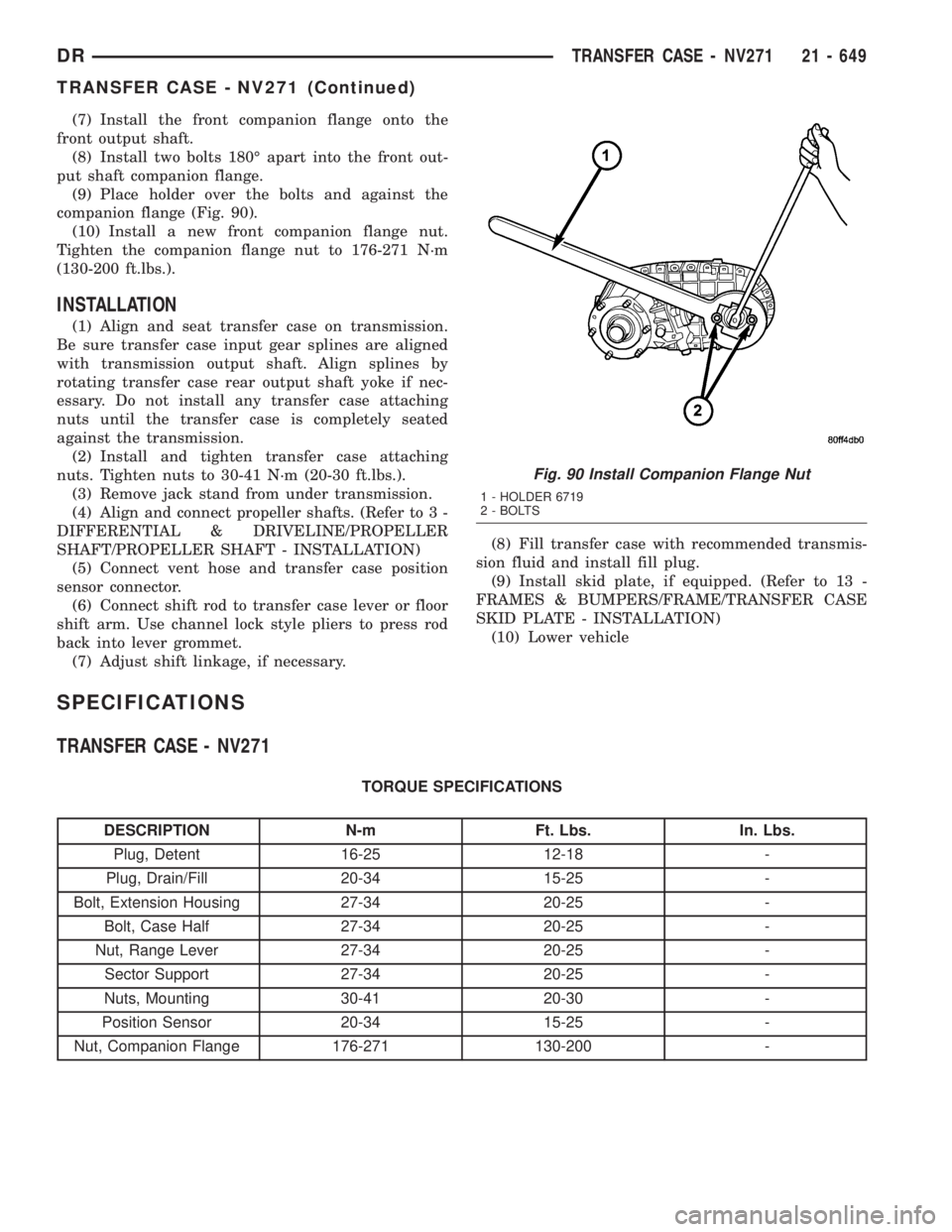
(9) Place holder over the bolts and against the
companion flange (Fig. 90).
(10) Install a new front companion flange nut.
Tighten the companion flange nut to 176-271 N´m
(130-200 ft.lbs.).
INSTALLATION
(1) Align and seat transfer case on transmission.
Be sure transfer case input gear splines are aligned
with transmission output shaft. Align splines by
rotating transfer case rear output shaft yoke if nec-
essary. Do not install any transfer case attaching
nuts until the transfer case is completely seated
against the transmission.
(2) Install and tighten transfer case attaching
nuts. Tighten nuts to 30-41 N´m (20-30 ft.lbs.).
(3) Remove jack stand from under transmission.
(4) Align and connect propeller shafts. (Refer to 3 -
DIFFERENTIAL & DRIVELINE/PROPELLER
SHAFT/PROPELLER SHAFT - INSTALLATION)
(5) Connect vent hose and transfer case position
sensor connector.
(6) Connect shift rod to transfer case lever or floor
shift arm. Use channel lock style pliers to press rod
back into lever grommet.
(7) Adjust shift linkage, if necessary.(8) Fill transfer case with recommended transmis-
sion fluid and install fill plug.
(9) Install skid plate, if equipped. (Refer to 13 -
FRAMES & BUMPERS/FRAME/TRANSFER CASE
SKID PLATE - INSTALLATION)
(10) Lower vehicle
SPECIFICATIONS
TRANSFER CASE - NV271
TORQUE SPECIFICATIONS
DESCRIPTION N-m Ft. Lbs. In. Lbs.
Plug, Detent 16-25 12-18 -
Plug, Drain/Fill 20-34 15-25 -
Bolt, Extension Housing 27-34 20-25 -
Bolt, Case Half 27-34 20-25 -
Nut, Range Lever 27-34 20-25 -
Sector Support 27-34 20-25 -
Nuts, Mounting 30-41 20-30 -
Position Sensor 20-34 15-25 -
Nut, Companion Flange 176-271 130-200 -
Fig. 90 Install Companion Flange Nut
1 - HOLDER 6719
2 - BOLTS
DRTRANSFER CASE - NV271 21 - 649
TRANSFER CASE - NV271 (Continued)
Page 2493 of 2895
POSITION SENSOR
DESCRIPTION
The transfer case position sensor is an electronic
device whose output can be interpreted to indicate
the transfer case's current operating mode. The sen-
sor consists of a five position, resistive multiplexed
circuit which returns a specific resistance value to
the Powertrain Control Module (PCM) for each trans-
fer case operating mode. The sensor is located on the
top of the transfer case, just left of the transfer case
centerline and rides against the sector plate rooster-comb. The PCM supplies 5VDC (+/- 0.5V) to the sen-
sor and monitors the return voltage to determine the
sector plate, and therefore the transfer case, position.OPERATION
During normal vehicle operation, the Powertrain
Control Module (PCM) monitors the transfer case
position sensor return voltage to determine the oper-
ating mode of the transfer case. Refer to the Operat-
ing Mode Versus Resistance table for the correct
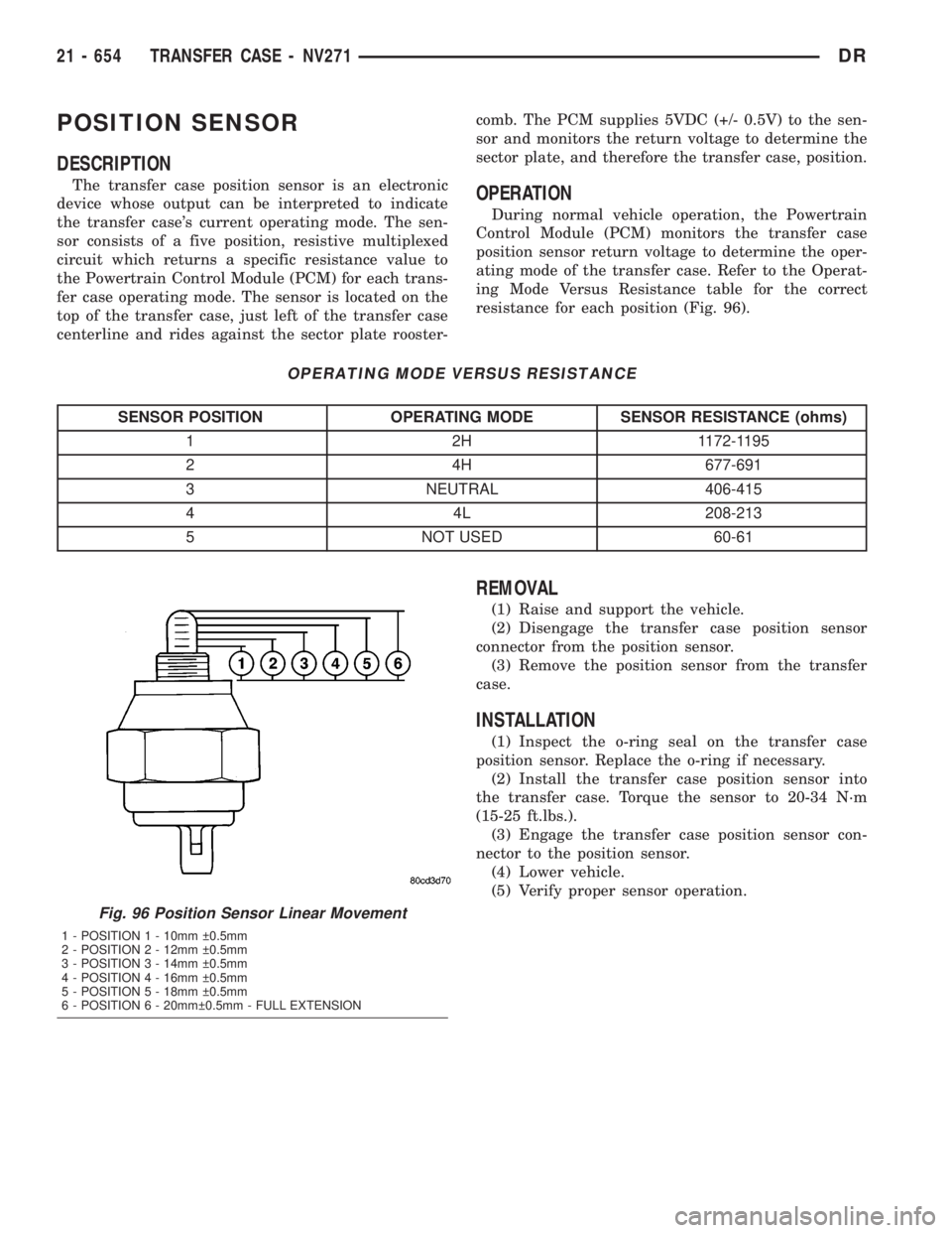
resistance for each position (Fig. 96).
OPERATING MODE VERSUS RESISTANCE
SENSOR POSITION OPERATING MODE SENSOR RESISTANCE (ohms)
1 2H 1172-1195
2 4H 677-691
3 NEUTRAL 406-415
4 4L 208-213
5 NOT USED 60-61
REMOVAL
(1) Raise and support the vehicle.
(2) Disengage the transfer case position sensor
connector from the position sensor.
(3) Remove the position sensor from the transfer
case.
INSTALLATION
(1) Inspect the o-ring seal on the transfer case
position sensor. Replace the o-ring if necessary.
(2) Install the transfer case position sensor into
the transfer case. Torque the sensor to 20-34 N´m
(15-25 ft.lbs.).
(3) Engage the transfer case position sensor con-
nector to the position sensor.
(4) Lower vehicle.
(5) Verify proper sensor operation.
Fig. 96 Position Sensor Linear Movement
1 - POSITION 1 - 10mm 0.5mm
2 - POSITION 2 - 12mm 0.5mm
3 - POSITION 3 - 14mm 0.5mm
4 - POSITION 4 - 16mm 0.5mm
5 - POSITION 5 - 18mm 0.5mm
6 - POSITION 6 - 20mm 0.5mm - FULL EXTENSION
21 - 654 TRANSFER CASE - NV271DR
Page 2499 of 2895
Condition Possible Cause Correction
Transfer case noisy while in, or
jumps out of, 4LO mode.1) Transfer case not completely
engaged in 4LO position.1) While rolling 2-3 MPH and the
transmission in NEUTRAL, or clutch
depressed on vehicles equipped
with a manual transmission, shift
transfer case to the 2WD or 4HI
position, and then back into the 4LO
position.
2) Range fork damaged, inserts
worn, or fork is binding on the shift
rail.2) Repair or replace components as
necessary.
3) Low range gear worn or
damaged.3) Repair or replace components as
necessary.
Lubricant leaking from transfer case
seals or vent.1) Transfer case overfilled. 1) Drain lubricant to the correct
level.
2) Transfer case vent closed or
restricted.2) Clean or replace vent as
necessary.
3) Transfer case seals damaged or
installed incorrectly.3) Replace suspect seal.
Abnormal tire wear. 1) Extended operation in 4HI mode
on dry surfaces,1) Operate vehicle in 2WD mode on
dry surfaces.
REMOVAL
(1) Shift transfer case into 2WD.
(2) Raise vehicle.
(3) Drain transfer case lubricant.
(4) Mark front and rear propeller shafts for align-
ment reference.
(5) Support transmission with jack stand.
(6) Remove the transfer case skid plate, if
equipped.
(7) Disconnect front and rear propeller shafts at
transfer case.
(8) Disconnect transfer case shift motor and mode
sensor wire connectors.
(9) Disconnect transfer case vent hose.
(10) Support transfer case with transmission jack.
(11) Secure transfer case to jack with chains.
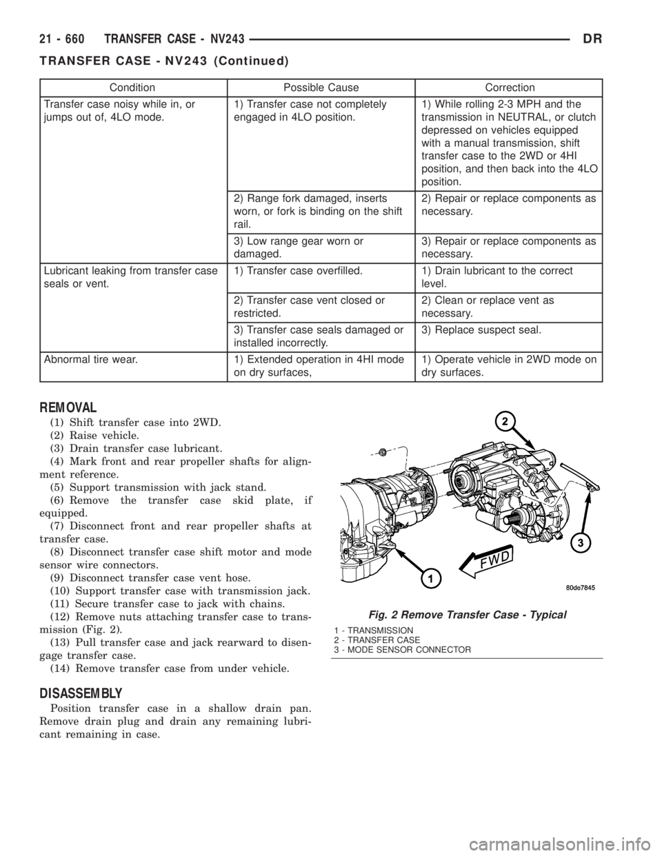
(12) Remove nuts attaching transfer case to trans-
mission (Fig. 2).
(13) Pull transfer case and jack rearward to disen-
gage transfer case.
(14) Remove transfer case from under vehicle.
DISASSEMBLY
Position transfer case in a shallow drain pan.
Remove drain plug and drain any remaining lubri-
cant remaining in case.
Fig. 2 Remove Transfer Case - Typical
1 - TRANSMISSION
2 - TRANSFER CASE
3 - MODE SENSOR CONNECTOR
21 - 660 TRANSFER CASE - NV243DR
TRANSFER CASE - NV243 (Continued)
Page 2518 of 2895
(2) Apply bead of MopartGasket Maker, or equiv-
alent, to mating surface of rear extension housing.
Keep sealer bead width to maximum of 3/16 inch. Do
not use excessive amount of sealer as excess could be
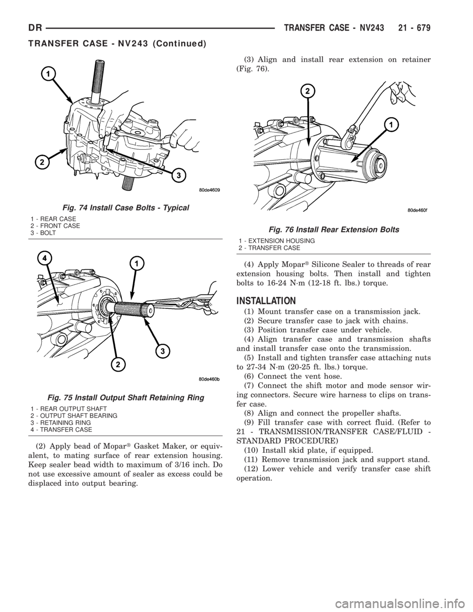
displaced into output bearing.(3) Align and install rear extension on retainer
(Fig. 76).
(4) Apply MopartSilicone Sealer to threads of rear
extension housing bolts. Then install and tighten
bolts to 16-24 N´m (12-18 ft. lbs.) torque.
INSTALLATION
(1) Mount transfer case on a transmission jack.
(2) Secure transfer case to jack with chains.
(3) Position transfer case under vehicle.
(4) Align transfer case and transmission shafts
and install transfer case onto the transmission.
(5) Install and tighten transfer case attaching nuts
to 27-34 N´m (20-25 ft. lbs.) torque.
(6) Connect the vent hose.
(7) Connect the shift motor and mode sensor wir-
ing connectors. Secure wire harness to clips on trans-
fer case.
(8) Align and connect the propeller shafts.
(9) Fill transfer case with correct fluid. (Refer to
21 - TRANSMISSION/TRANSFER CASE/FLUID -
STANDARD PROCEDURE)
(10) Install skid plate, if equipped.
(11) Remove transmission jack and support stand.
(12) Lower vehicle and verify transfer case shift
operation.
Fig. 74 Install Case Bolts - Typical
1 - REAR CASE
2 - FRONT CASE
3 - BOLT
Fig. 75 Install Output Shaft Retaining Ring
1 - REAR OUTPUT SHAFT
2 - OUTPUT SHAFT BEARING
3 - RETAINING RING
4 - TRANSFER CASE
Fig. 76 Install Rear Extension Bolts
1 - EXTENSION HOUSING
2 - TRANSFER CASE
DRTRANSFER CASE - NV243 21 - 679
TRANSFER CASE - NV243 (Continued)
Page 2525 of 2895
²A flashing operating mode LED for the desired
gear indicates that a shift to that position has been
requested, but all of the driver controllable conditions
have not been met. This is in an attempt to notify
the driver that the transmission needs to be put into
NEUTRAL, the vehicle speed is too great, or some
other condition outlined (other than a diagnostic fail-
ure that would prevent this shift) elsewhere (Refer to
8 - ELECTRICAL/ELECTRONIC CONTROL MOD-
ULES/TRANSFER CASE CONTROL MODULE -
OPERATION) is not met. Note that this flashing will
continue indefinitely until the conditions are eventu-
ally met, or the selector switch position is changed,
or if diagnostic routines no longer allow the
requested shift.
²If the driver attempts to make a shift into trans-
fer case NEUTRAL, and any of the driver controlla-
ble conditions are not met, the request will be
ignored until all of the conditions are met or until
the NEUTRAL select button is released. Additionally
the neutral lamp will flash, or begin to flash while
the button is depressed and operator controllable
conditions are not being met. All of the LED's except
the Neutral will flash if any of the operator control-
lable conditions for shifting are not met while the
Neutral button is depressed. This9toggle9type of fea-
ture is necessary because the TCCM would interpret
another request immediately after the shift into
transfer case NEUTRAL has completed.
²No LED's illuminated indicate a fault in the
transfer case control system.
SHIFT MOTOR
DESCRIPTION
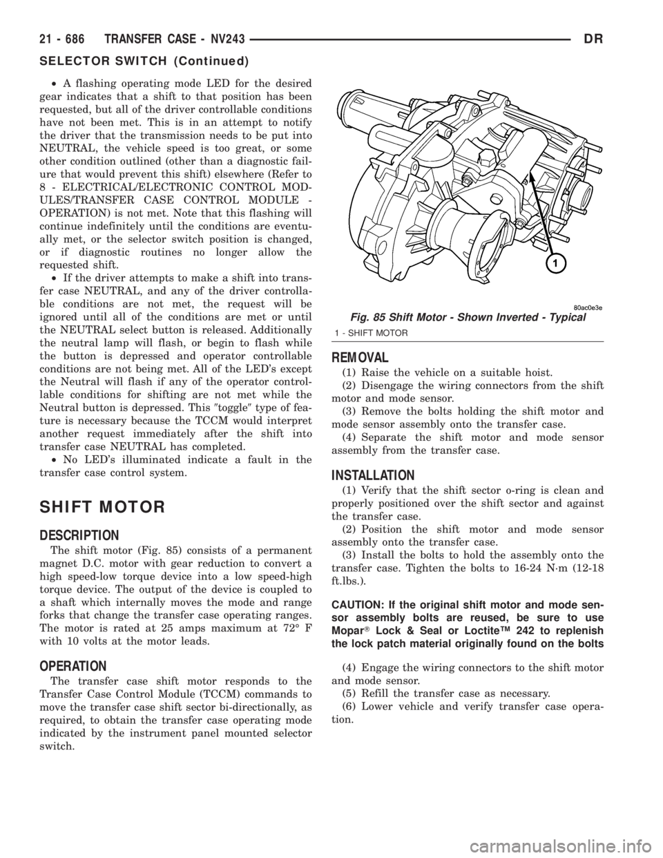
The shift motor (Fig. 85) consists of a permanent
magnet D.C. motor with gear reduction to convert a
high speed-low torque device into a low speed-high
torque device. The output of the device is coupled to
a shaft which internally moves the mode and range
forks that change the transfer case operating ranges.
The motor is rated at 25 amps maximum at 72É F
with 10 volts at the motor leads.
OPERATION
The transfer case shift motor responds to the
Transfer Case Control Module (TCCM) commands to
move the transfer case shift sector bi-directionally, as
required, to obtain the transfer case operating mode
indicated by the instrument panel mounted selector
switch.
REMOVAL
(1) Raise the vehicle on a suitable hoist.
(2) Disengage the wiring connectors from the shift
motor and mode sensor.
(3) Remove the bolts holding the shift motor and
mode sensor assembly onto the transfer case.
(4) Separate the shift motor and mode sensor
assembly from the transfer case.
INSTALLATION
(1) Verify that the shift sector o-ring is clean and
properly positioned over the shift sector and against
the transfer case.
(2) Position the shift motor and mode sensor
assembly onto the transfer case.
(3) Install the bolts to hold the assembly onto the
transfer case. Tighten the bolts to 16-24 N´m (12-18
ft.lbs.).
CAUTION: If the original shift motor and mode sen-
sor assembly bolts are reused, be sure to use
MoparTLock & Seal or LoctiteŸ 242 to replenish
the lock patch material originally found on the bolts
(4) Engage the wiring connectors to the shift motor
and mode sensor.
(5) Refill the transfer case as necessary.
(6) Lower vehicle and verify transfer case opera-
tion.
Fig. 85 Shift Motor - Shown Inverted - Typical
1 - SHIFT MOTOR
21 - 686 TRANSFER CASE - NV243DR
SELECTOR SWITCH (Continued)
Page 2528 of 2895
Condition Possible Cause Correction
Transfer case noisy while in, or
jumps out of, 4LO mode.1) Transfer case not completely
engaged in 4LO position.1) While rolling 2-3 MPH and the
transmission in NEUTRAL, or clutch
depressed on vehicles equipped
with a manual transmission, shift
transfer case to the 2WD or 4HI
position, and then back into the 4LO
position.
2) Range fork damaged, inserts
worn, or fork is binding on the shift
rail.2) Repair or replace components as
necessary.
3) Low range gear worn or
damaged.3) Repair or replace components as
necessary.
Lubricant leaking from transfer case
seals or vent.1) Transfer case overfilled. 1) Drain lubricant to the correct
level.
2) Transfer case vent closed or
restricted.2) Clean or replace vent as
necessary.
3) Transfer case seals damaged or
installed incorrectly.3) Replace suspect seal.
Abnormal tire wear. 1) Extended operation in 4HI mode
on dry surfaces,1) Operate vehicle in 2WD mode on
dry surfaces.
REMOVAL
(1) Shift transfer case into 2WD.
(2) Raise vehicle.
(3) Drain transfer case lubricant.
(4) Mark front and rear propeller shafts for align-
ment reference.
(5) Support transmission with jack stand.
(6) Remove the transfer case skid plate, if
equipped.
(7) Disconnect front and rear propeller shafts at
transfer case.
(8) Disconnect transfer case shift motor and mode
sensor wire connectors.
(9) Disconnect transfer case vent hose.
(10) Support transfer case with transmission jack.
(11) Secure transfer case to jack with chains.
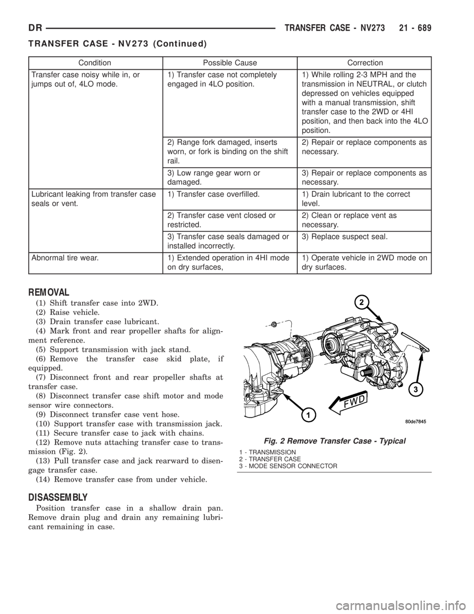
(12) Remove nuts attaching transfer case to trans-
mission (Fig. 2).
(13) Pull transfer case and jack rearward to disen-
gage transfer case.
(14) Remove transfer case from under vehicle.
DISASSEMBLY
Position transfer case in a shallow drain pan.
Remove drain plug and drain any remaining lubri-
cant remaining in case.
Fig. 2 Remove Transfer Case - Typical
1 - TRANSMISSION
2 - TRANSFER CASE
3 - MODE SENSOR CONNECTOR
DRTRANSFER CASE - NV273 21 - 689
TRANSFER CASE - NV273 (Continued)
Page 2552 of 2895
(7) Install the front companion flange onto the
front output shaft.
(8) Install two bolts 180É apart into the front out-
put shaft companion flange.
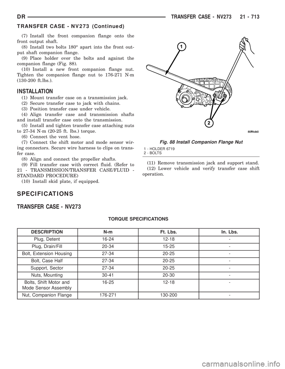
(9) Place holder over the bolts and against the
companion flange (Fig. 88).
(10) Install a new front companion flange nut.
Tighten the companion flange nut to 176-271 N´m
(130-200 ft.lbs.).
INSTALLATION
(1) Mount transfer case on a transmission jack.
(2) Secure transfer case to jack with chains.
(3) Position transfer case under vehicle.
(4) Align transfer case and transmission shafts
and install transfer case onto the transmission.
(5) Install and tighten transfer case attaching nuts
to 27-34 N´m (20-25 ft. lbs.) torque.
(6) Connect the vent hose.
(7) Connect the shift motor and mode sensor wir-
ing connectors. Secure wire harness to clips on trans-
fer case.
(8) Align and connect the propeller shafts.
(9) Fill transfer case with correct fluid. (Refer to
21 - TRANSMISSION/TRANSFER CASE/FLUID -
STANDARD PROCEDURE)
(10) Install skid plate, if equipped.(11) Remove transmission jack and support stand.
(12) Lower vehicle and verify transfer case shift
operation.
SPECIFICATIONS
TRANSFER CASE - NV273
TORQUE SPECIFICATIONS
DESCRIPTION N-m Ft. Lbs. In. Lbs.
Plug, Detent 16-24 12-18 -
Plug, Drain/Fill 20-34 15-25 -
Bolt, Extension Housing 27-34 20-25 -
Bolt, Case Half 27-34 20-25 -
Support, Sector 27-34 20-25 -
Nuts, Mounting 30-41 20-30 -
Bolts, Shift Motor and
Mode Sensor Assembly16-25 12-18 -
Nut, Companion Flange 176-271 130-200 -
Fig. 88 Install Companion Flange Nut
1 - HOLDER 6719
2 - BOLTS
DRTRANSFER CASE - NV273 21 - 713
TRANSFER CASE - NV273 (Continued)
Page 2559 of 2895
²A flashing operating mode LED for the desired
gear indicates that a shift to that position has been
requested, but all of the driver controllable conditions
have not been met. This is in an attempt to notify
the driver that the transmission needs to be put into
NEUTRAL, the vehicle speed is too great, or some
other condition outlined (other than a diagnostic fail-
ure that would prevent this shift) elsewhere (Refer to
8 - ELECTRICAL/ELECTRONIC CONTROL MOD-
ULES/TRANSFER CASE CONTROL MODULE -
OPERATION) is not met. Note that this flashing will
continue indefinitely until the conditions are eventu-
ally met, or the selector switch position is changed,
or if diagnostic routines no longer allow the
requested shift.
²If the driver attempts to make a shift into trans-
fer case NEUTRAL, and any of the driver controlla-
ble conditions are not met, the request will be
ignored until all of the conditions are met or until
the NEUTRAL select button is released. Additionally
the neutral lamp will flash, or begin to flash while
the button is depressed and operator controllable
conditions are not being met. All of the LED's except
the Neutral will flash if any of the operator control-
lable conditions for shifting are not met while the
Neutral button is depressed. This9toggle9type of fea-
ture is necessary because the TCCM would interpret
another request immediately after the shift into
transfer case NEUTRAL has completed.
²No LED's illuminated indicate a fault in the
transfer case control system.
SHIFT MOTOR
DESCRIPTION
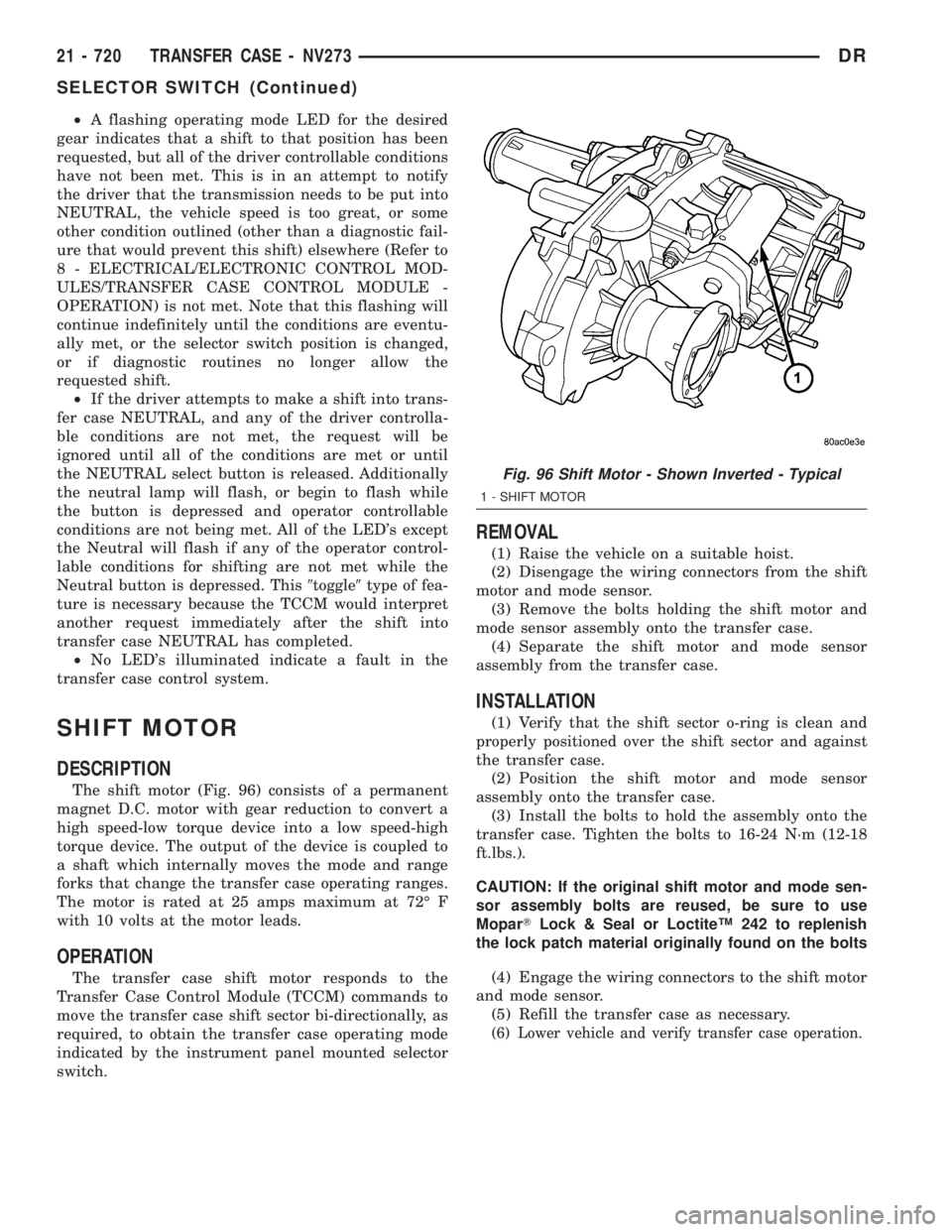
The shift motor (Fig. 96) consists of a permanent
magnet D.C. motor with gear reduction to convert a
high speed-low torque device into a low speed-high
torque device. The output of the device is coupled to
a shaft which internally moves the mode and range
forks that change the transfer case operating ranges.
The motor is rated at 25 amps maximum at 72É F
with 10 volts at the motor leads.
OPERATION
The transfer case shift motor responds to the
Transfer Case Control Module (TCCM) commands to
move the transfer case shift sector bi-directionally, as
required, to obtain the transfer case operating mode
indicated by the instrument panel mounted selector
switch.
REMOVAL
(1) Raise the vehicle on a suitable hoist.
(2) Disengage the wiring connectors from the shift
motor and mode sensor.
(3) Remove the bolts holding the shift motor and
mode sensor assembly onto the transfer case.
(4) Separate the shift motor and mode sensor
assembly from the transfer case.
INSTALLATION
(1) Verify that the shift sector o-ring is clean and
properly positioned over the shift sector and against
the transfer case.
(2) Position the shift motor and mode sensor
assembly onto the transfer case.
(3) Install the bolts to hold the assembly onto the
transfer case. Tighten the bolts to 16-24 N´m (12-18
ft.lbs.).
CAUTION: If the original shift motor and mode sen-
sor assembly bolts are reused, be sure to use
MoparTLock & Seal or LoctiteŸ 242 to replenish
the lock patch material originally found on the bolts
(4) Engage the wiring connectors to the shift motor
and mode sensor.
(5) Refill the transfer case as necessary.
(6) Lower vehicle and verify transfer case operation.
Fig. 96 Shift Motor - Shown Inverted - Typical
1 - SHIFT MOTOR
21 - 720 TRANSFER CASE - NV273DR
SELECTOR SWITCH (Continued)